1
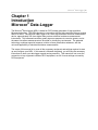
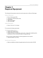
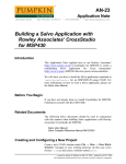
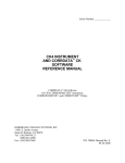
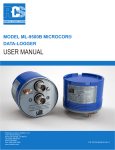
®
Microcor Data Logger
Reference Manual
Rohrback Cosasco Systems, Inc.
11841 East Smith Avenue
Santa Fe Springs, CA 90670
Tel: +1 (562) 949-0123
Fax: +1 (562) 949-3065
Email: [email protected]
Website: http://www.cosasco.com
P/N 702195-Manual rev.-
Microcor® Data Logger | i CHECKMATE™ DL is a trademark of Rohrback Cosasco Systems, Inc. CORROSOMETER®,
CORRDATA®, MICROCOR®, MICROCOR® TOOLS ,and CORRDATA® PLUS are registered
trademarks of Rohrback Cosasco Systems, Inc.
Windows® is a registered trademark of Microsoft Corporation.
No part of this manual may be reproduced or transmitted in any form or by any means,
electronic or mechanical, including photocopying and recording, for any purpose, without the
express written permission of Rohrback Cosasco Systems, Inc.
Microcor® Data‐Logger | ii Table of Contents
Chapter 1 Introduction…...........................................................................................................1
Chapter 2 Specification .............................................................................................................2 Chapter 3 Required Equipment ................................................................................................3 Chapter 4 MDL Configuration ...................................................................................................4 Microcor Tools Method .............................................................................................................6 CheckMate DL Method .............................................................................................................9 Chapter 5 Retrieval and Plotting Data....................................................................................14 Chapter 6 Physical Installation...............................................................................................17 Power Module Installation .......................................................................................................17 Mount the Transmitter .............................................................................................................18 Direct Probe Mounting ............................................................................................................18 RCS Mounting Accessories ....................................................................................................19 Appendix A Product Certifications ........................................................................................21 Microcor® Data‐Logger | iii Microcor® Data‐Logger | 1 Chapter 1
Introduction
Microcor® Data-Logger
The Microcor® Data-Logger (MDL) is based on RCS's latest generation of high-resolution
Microcor technology. The MDL operates in conjunction with the high-resolution Microcor probes
that RCS offers. The Microcor Data-Logger is an 18 bit high-resolution corrosion measurement
device, approximately 256 times higher than previous electrical resistance measurement
instruments. This increased resolution greatly improves response to corrosion upsets, and at
the same time allows measurements to be made in virtually any environment. The patented
technology combines speed of response, similar to linear polarization resistance, with the
universal applicability of electrical resistance measurements.
The scope of this manual is to cover all the necessary equipment and settings required to start
up and configure your MDL. If this manual is followed completely, you will have the necessary
instructions to have your data logger up and running smoothly. This manual will not cover the
connection of any equipment outside of RCS equipment, nor will it cover settings not used by
RCS equipment. Microcor® Data‐Logger | 2
Chapter 2
Specifications
Mechanical Specifications:
•
Weight: 7.5 lbs (3.4kg) •
Dimensions: 6.38” x 4.40” Electrical Specifications:
•
Resolution:
18 bit (1 part in 262,144)
•
Power Supply:
7.2V Lithium Power Module
•
Probe compatibility:
All Microcor Probes
•
Operating Temperature Range:
-40C to +70C
•
Maximum Data Storage:
8000 Readings (Circular Buffer)
•
Battery Life:
3 years at 10 min measurement interval
•
Communications:
Microcor Tools
•
Handheld:
Checkmate DL
•
Proprietary communications protocol
Microcor® Data‐Logger | 3
Chapter 3
Required Equipment
The following lists the equipment required to correctly setup and run a Microcor Data-Logger.
Hardware Requirements:
•
•
•
•
•
Microcor Data-Logger (MDL)
Checkmate DL handheld (Hazloc area)
Power Module
USB to Serial Adapter
Limo to Serial cable Software Requirements:
•
Microcor Tools Ver. 5.0 or Greater
PC must meet the following requirements:
Operating System Requirements:
• Windows 2000, service pack 4
• Windows Server 2003 or newer
• Windows XP (Home or Professional), service pack 1 or higher (If the operating system
requirement is not met, the setup will display a message and stop).
If the user manual is being installed, the following application is also required:
• Adobe® Acrobat® 5.0 (or newer)
Hard disk space Requirements:
•
Maximum installation (including all upgrades performed by the setup disc): 250 MB
Microcor® Data‐Logger | 4
Chapter 4
MDL Configuration
This chapter will cover the options available for configuration of the MDL. Option 1 is use of
Microcor Tools configuration software in a non-hazardous location. A local connection between
a PC/Laptop and the MDL needs to be established. In addition to configuration, Microcor Tools
is also used to download and analyze the MDL data. Supplementary data analysis is covered in
the Microcor Tools Manual. Option 2 is use of the Checkmate DL handheld. The Checkmate
DL is a Hazloc Zone I approved device that will configure your MDL and act as a shuttle device
for downloading data.
Checklist
9
9
Install Microcor Tools Software (Non-Hazloc area). Be sure the power module is installed in the MDL prior to start of configuration. 9 Connect the communication cable (PN: 748110-9A) to both the computer and the MDL.
9 If using USB to RS232 adapter, be sure to install supplied drivers by the manufacturer.
Installation
1. Install Microcor Tools Software a. Insert the Setup and Installation CD that was included with the MDL Installation Kit.
b. Click Install/Setup and follow screens shown below.
c. Click OK.
Microcor® Data‐Logger | 5
d. Leave the default directory shown, click on the icon to continue.
e. Leave the default Program Group, click on continue to proceed.
*Note: If any Version Conflict is prompted, click yes to keep your existing files.
f.
Setup is complete, click OK.
Microcor® Data‐Logger | 6
Microcor Tools Configuration Method (Software)
1. Run Microcor Tools
2. Create a “New Site” if one has not been created already.
New Site
Microcor® Data‐Logger | 7
3. Initialize Data-Logger Communication
a.
b.
c.
Select Com Port (This can be found in device manager of the PC).
Save Site Configuration.
Start Communication.
Ignore
This
Section
Com Port
Start
Save
Microcor® Data‐Logger | 8
4. Configure (Configure/DL Transfer Tab)
a.
b.
c.
d.
e.
f.
g.
h.
Select an Address to use by clicking the + or – buttons (0 to 99).
Check Data Logger as Connection type.
Select probe and element type from drop down menus.
Input the probe span.
Input desired sampling interval (10-60).
Input desired tag name.
Click Store Setup to initialize configuration.
Click Apply to save configuration.
i. To modify configuration, edit white text fields and click Store Setup followed by Apply.
The MDL is now configured and ready to take Measurements. Go to Data Display section to
read instructions on retrieving and viewing data.
Microcor® Data‐Logger | 9
CheckMate DL Method (Hardware – Hazloc Safe)
The Checkmate DL is designed to configure and gather data from all Microcor Data-Loggers.
The following section will explain the data collection procedure from the Microcor Data-Logger.
1. Read Data-Logger Configuration and Status
Configurations already set into the Data-Logger are easily read with the Checkmate DL.
Connect the Checkmate DL to the Data-Logger with the provided adapter cable connector.
From the Standby screen, press Read (F1) to proceed to the following display with the attached
Data-Logger information:
ID: XX XXXXXXXXXXXX
MMM DD, YYYY HH:MM
Read Read Set
Stat
Data Clock Exit
Press Read Stat (F1) to display the Data-Logger time, number of readings and the sample rate
as shown below:
MMM DD, YYYY HH:MM
Readings: XXXXX
Samp Rate: XXXXX
More
Exit
Press More (F1) to continue to the next display which shows the battery, memory and
transmission information as shown below. Battery status will show OK or LOW. Memory and
Transmission will show OK or BAD depending on their status.
Batt: OK/LOW
Mem: OK/BAD
Trans: OK/BAD
Exit
2. Reading / Clearing Data from Microcor Data-Loggers
To read a Data-Logger, connect the Checkmate DL to the Data-Logger with the provided
adapter cable connector. From the Standby screen, press Read (F1) to proceed to the
following display with the attached Data Logger information:
ID: XX XXXXXXXXXXXX
MMM DD, YYYY HH:MM
Read Read Set
Stat
Data Clock Exit
Press Read Data (F2); Checkmate DL will perform a series of internal checks and proceed
accordingly. First, Checkmate DL will check whether the ID is properly assigned. If the ID is not
properly assigned, it will prompt the user to set the Data-Logger ID and the Tag information. It
Microcor® Data‐Logger | 10
will then determine if any readings for this ID are stored in the Checkmate DL. If any data for
the ID exists in the Checkmate DL, then the user will be prompted to either Overwrite (F1) or
Abort (F4). Overwriting will delete the existing data for that ID and replace it with the new data
being read. Once these internal checks are performed and any issues resolved, Checkmate DL
will proceed to the following screen:
Data Logger ID: XX
Tag: XXXXXXXXXXXX
Start
Exit
Press Start (F1) from the above screen to begin the read process. The Checkmate DL will show
the following screen during data transfer.
Getting Data
Please Wait
Approx XX.X minutes
If “NO MEMORY SPACE FOR READINGS” screen appears (shown below), then the
Checkmate DL memory will need to be cleared before transferring the data. It is recommended
that ALL existing data on the Checkmate DL be transferred to a PC prior to erasing ANY data.
Refer to the section on Clearing the Checkmate DL Memory on the Checkmate DL reference
manual.
NO MEMORY SPACE
FOR READINGS
Exit
Once the data is successfully read and transferred, it is displayed as shown below. Users can at
this time elect to delete the Data-Logger content if desired.
Note:
All data stored for the ID on the Checkmate DL will be erased if
“Clear” button is pressed.
Press Clear (F1) to clear Data-Logger readings or Next (F4) to return back to the Data-Logger
information screen without clearing the readings.
Last Reading xxxxxxx
MMM DD, YYYY HH:MM
Number Reads XXXXX
Next
Clear
WARNING!
It is recommended to clear the data in the Data-Logger after transfer to
the Checkmate DL. This reduces the amount and time of data transfer for
future downloads. The data is then appended to the previous data when
transferring the data from the Checkmate DL to the PC. Refer to the
Transferring Collected Data from Checkmate DL to PC section.
Microcor® Data‐Logger | 11
3. Transferring Collected Data from Checkmate DL to PC
Data-Logger data is downloaded to the PC using the provided Microcor Tools Software
program. Connect the Checkmate DL instrument to the 9 pin serial port on the PC using the
provided cable. If there is no serial port in the computer, use the included serial-to-USB
converter cable to complete the connection. Make sure to set the correct COM port number on
the Microcor Tools Software program Data-Logger Communication area (in most cases this
will be COM 1, however verify this in the device manager).
Checkmate DL Data Transfer Procedure
From the Standby screen, press Data (F3) to advance to the following display:
Transfer Data
Connect to PC
Start
Exit
Press the Start (F1) to proceed to the next screen. Use Next (F2) and Prev (F3) to navigate the
ID list (0 – 99) and select the desired ID to transfer data (shown below).
Data Logger ID: XX
Tag: XXXXXXXXXXXX
Start
Next
Prev
Exit
Once the ID is selected, press Start (F1). Following screen will appear:
Ready to Transfer
Data using Microcor
Software from RCS
Exit
Note:
Make sure that the data (ID of the Data-Logger) set in the Checkmate DL to be
transferred corresponds with the Address selected in the Microcor Tools
Software before transferring the data.
Data is now ready for transfer from the Checkmate DL to the PC. On the Microcor Tools
Software program, select the Site and navigate to the Config/DL Transfer screen, select the
Address and choose Data Logger as the Connection type and Microcor as the Instrument
(see image below). Click the Read Data command button to begin the transmission. It is also
possible to click the Read Setup command button to transfer the configuration data of the dataLogger to the Data Logger section on the Config/DL Transfer screen (shown below).
Microcor® Data‐Logger | 12
If data already exists for the chosen address, following dialogue box will appear:
-
Press Yes to add the new data onto an existing file. This is the normal method if the
data in the Data-Logger is deleted after it is collected each time in order to speed data
transfer. It also prevents reaching the maximum storage capacity in the data logger at
which time the data collection stops.
-
Press No if all of the data in the Checkmate DL is to replace an existing file. This should
be used if the data in the Data-logger is NOT cleared each time it is read. In this case
the existing file is automatically archived.
-
Press Cancel to exit the Read Data function.
Microcor® Data‐Logger | 13
Note:
The Microcor Data-Logger will store up to 8000 readings before collection
memory is fully allocated, then the collection of data will halt until data is cleared
from memory.
After a selection has been made, a counter in the status bar indicates the number of samples to
be transferred. Status bar will read End of Transfer when the data is successfully transferred
from the data logger to the Microcor Tools program. During the data transfer, the following
screen will be displayed on the Checkmate DL:
Data Transfer in
Progress!
xxxxx Readings Left
Exit
The number of readings (xxxxx) counts down as the data is transferred to Microcor Tools. Upon
successful transmission, Checkmate DL will show the following screen:
Data Transfer Done!
Exit
Press Exit (F4) to return to the Data Transfer screen to choose another ID for data transfer.
Note:
Information from only one Data-Logger can be transferred at a
time, when transferring information of more than one Data-Logger,
change the Address on the Microcor Tools Software program
for each transfer so that all data is not transferred only to one ID
address.
In case of any error messages displayed on Checkmate DL, check connections between
Checkmate DL and the PC, make sure that Microcor Tools Software program is running and
that the correct COM port is selected.
If data is still not transferred after checking the connection between the PC and Checkmate DL,
please see the Troubleshooting section for further help.
Microcor® Data‐Logger | 14
Chapter 5
Retrieving and Plotting Data
Microcor Tools allows retrieving and plotting of corrosion data. Microcor Tools – History
Viewer can be used to view data collected Online or by Data-Logger connection methods.
To open the Microcor Tools – History Viewer (graph feature), select the site from the
Site/Communications tab, select the Address from the Config/DL Transfer tab, and click the
Show Data command button. Alternate method to enter the History Viewer is to navigate to the
Data Display tab and double-clicking the Tag of the desired unit.
Microcor® Data‐Logger | 15
In the above screen, the top graph is the Metal Loss and the bottom graph presents the probe
Temperature (when applicable). The bottom graph can be switched to show the Corrosion or
Erosion Rate for the same set of data when the Corrosion or Erosion Rate button is selected.
To show the corrosion rate graph, click the Corrosion or Erosion Rate command button (see
section below for more details). Click the Temperature command button to display the probe
temperature graph.
Note:
The Temperature graph will open as the default bottom graph if the transmitter
supports temperature monitoring capabilities and if the Probe Temperature
check-box is selected; otherwise the graph area will remain blank (to view the
Corrosion or Erosion Rate graph, Corrosion or Erosion Rate command button
must be pressed. It will not open as a default graph). Data-loggers do not support
temperature measurements.
Use the upper Dimension box (top right-hand corner of the screen) to select the Metal Loss Yaxis units in mils, µm, mm or Probe Life Units (PLU). Use the lower Dimension box (middle
right-hand side of the screen) to select units for the Temperature graph in ºC or ºF or mpy,
mmpy or µmpy units if Corrosion or Erosion Rate graph is selected.
Microcor® Data‐Logger | 16
Corrosion/Erosion Rate is calculated by linear regression. This Regression Interval may be readjusted and the Corrosion/Erosion Rate recalculated by clicking the Recalculate command
button. The default may suit many online systems but can be changed to optimize noise against
sensitivity of the computed corrosion or erosion rate. The 24h Filter can be enabled at the
Rate/Alarms Settings area (in the Config/DL Transfer screen) to reduce the effects of any
diurnal (24) thermal noise. The Alarm Level units are directly related to the above selected
units and can only be changed by the above settings.
Once the settings have been optimized, the rate data may be saved with the Store button.
When closing the graphical display window (History Viewer) a dialog box will prompt to save
the settings. Select Yes to store these settings for automatic application to all new data.
Select (or type in) values for Zero and Gain to calibrate the measurement. If calibration
parameters are unknown for probes and transmitters, select 0 for Zero and 31 for Gain.
The Zero Offset will allow users to change the y-axis reference point to zero (0) by changing
the value. This is a helpful feature when conducting tests to graphically view the data from a
convenient starting point. It is recommended that this be returned to original value of zero so
determination of probe life can be done accurately.
Microcor® Data‐Logger | 17
Chapter 6
Physical Installation
Power Module Installation
Ensure that the Power Module is connected to the data-logger. Power Module (RCS P/N
748400) is intrinsically safe and may be connected/disconnected in a hazardous location.
*INTRINSICALLY SAFE
BATTERY PACK
PROBE
CONNECTOR
COVER
*BATTERY CAN ONLY
BE INSTALLED IN
ONE DIRECTION
DATA PORT
MAIN HOUSING
Mount the Data-Logger
The data-logger can be installed on the top, side, or bottom of the line according to the probe
installation. Choose the best installation configuration that corresponds to the location of the
probe.
Grounding
Microcor® Data‐Logger | 18
A 8 to 14 AWG grounding wire can be attached to the data-logger at the grounding lug.
Connect the ground wire to earth ground per local electrical code.
Direct Probe Mounting
Top of the Line
a. Attach connector and tighten connector nut to mount the data-logger to the probe
adapter.
DATA PORT
DATA PORT
RETRACTABLE
PROBE ASSEMBLY
WITH SAFETY CLAMP
PROBE ADAPTER
COSASCO ACCESS
FITTING WITH PLUG
ASSEMBLY
ACCESS VALVE
PROBE ASSEMBLY
PROBE ASSEMBLY
Data-logger Mounted on a Cosasco Access
Fitting With Retrievable Probe
Data-Logger With a Retractable Probe Assembly
Side of the Line
a. Attach connector and tighten connector nut to mount the data-logger to the probe
adapter.
Microcor® Data‐Logger | 19
DATA PORT
Data-logger With Fixed Probe Mounted on the Side of the Pipe
Bottom of the Line
a. Attach connector and tighten connector nut to mount the data-logger to the probe
adapter.
PROBE ASSEMBLY
DATA PORT
Data-logger Mounted on the Side of the Pipe
Optional Remote Mounting
(Bottom of the Line shown)
a. Secure the data-logger to the remote mounting post using appropriate accessories.
b. Attach connector and tighten connector nut of the optional flexible cable to the probe
adapter and attach the other end to the data-logger.
MOUNTING
BRACKET
MOUNTING POST
PROBE ASSEMBLY
MOUNTED ON THE
UNDERSIDE OF THE
PIPE
FLEXIBLE CABLE
(OPTIONAL)
Microcor® Data‐Logger | 20
Data-logger Mounted in a Remote Location
RCS Mounting Accessories
2” DIA. MOUNTING POST
(NOT SUPPLIED)
MOUNTING PLATE
LOCK WASHER
AND HEX NUT
“U” BOLT
Microcor® Data‐Logger | 21
Appendix A
Product Certifications: PLEASE REFER
TO MWT-3905