1
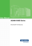
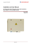
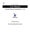
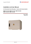
SOLAR POWER CONTROL SYSTEM “SPCS“ type Installation and User Manual Sofia, December - 2013 Solar Power Control System_User Manual-Rev.00.docx Contents 1 2 3 4 5 Introduction ............................................................................................ 3 1.1 Instructions for safety operation ....................................................... 4 1.2 Guarantees ...................................................................................... 4 1.3 Scope of delivery ............................................................................. 4 1.4 Technical parameters ...................................................................... 5 1.5 Label with technical parameters....................................................... 6 Warnings for danger and attention ....................................................... 7 Installation of Solar Power Control System - SPCS type .................... 8 3.1 Mechanical installation ..................................................................... 8 3.2 Opening of the SPCS unit ................................................................ 9 3.2.1 Door opening ....................................................................... 9 3.3 Block scheme of the SPCS unit ..................................................... 10 3.4 Choice of PV fuses ........................................................................ 10 3.5 Choice of place for installation ....................................................... 11 3.6 Electrical installation ...................................................................... 12 3.6.1 Cable inputs ...................................................................... 12 3.6.2 Overview of Main Components location ............................ 13 3.6.3 Electrical Connection of SPCS unit ................................... 14 3.6.4 Connection of PV strings ................................................... 14 3.6.5 Connection of pump to SPCS unit and SPCS grounding .. 15 3.6.6 Connection of the Communication Interface ..................... 16 3.6.7 Input – Output Interface description of the inverter module17 3.6.8 Software adjustment of Solar Power Inverter Module ....... 19 3.6.9 LED indication description ................................................. 19 3.6.10 Connection of SPCS communication modules .................. 20 3.6.11 Control switch description ................................................. 21 Running into exploitation .................................................................... 22 4.1 SPCS unit switching ON ................................................................ 22 4.2 SPCS unit switching OFF............................................................... 23 Replacement of defected components ............................................... 24 5.1 Replacement of fuse ...................................................................... 24 5.2 Replacement of discharger for overvoltage protection (arresters) . 25 5.3 Replacement of fan and finger guard filters ................................... 25 5.4 Replacement of the fan .................................................................. 26 Solar Power Control System_User Manual-Rev.00.docx 2/26 1 Introduction The SOLAR POWER CONTROL SYSTEM – SPCS devices are designed to complete autonomous solar equipment for direct supply of three-phase electrical motors driving pump installations. Example diagram of solar pumps installation: The system consists of following components: - - PV modules, covering the required power and divided into strings; SPCS module – SOLАР POWER CONTROL SYSTEM – the device converts the solar radiation energy into three-phase voltage for the pump motor, securing all necessary protections of the system, independent (autonomous) supply of the components in the system as well as the possibility for remote monitoring and control of the system (optional). Water pump – chosen with suitable capacity depending on the water source and the water level depth. Tank for collection of pumped water or system for irrigation. Solar Power Control System_User Manual-Rev.00.docx 3/26 1.1 Instructions for safety operation The present manual contains important instructions for safety operation, start running into exploitation and operation with complete units (panels) type SPCS. This manual has to be kept together or near the equipment any time! Photovoltaic installations operate with dangerous for life voltages. All activities regarding assembling and maintenance have to be performed by authorized personal, familiar with installation, start running into exploitation and operation of photovoltaic equipment and installations. The unit must be used exclusively for purposes, for which it is intended. For good and safety operation of the product, it is important the transport and store keeping to be good, as well as all prescriptions for assembling and installation, service and maintenance to be kept. Respective regional and specific for the country regulations to be kept, as well as the requirements, described in the present document, including instructions for location and assembling (for example the cross section of connecting cables, performing the tightening torque on mechanical and electrical connections, etc.). Used symbols and warning signs: DANGER DANGER means risky situation which, if it is not avoided, can bring to death or to serious injury. ATTENTION ATTENTION refers to cases, which are not connected with human injury. Not conforming to this warning sign can bring to material damages. 1.2 Guarantees The data and instructions for assembling and maintenance, given in this manual, are revised regularly and all corrections are included in next issues. In case of breaking the assembling instructions, the guarantee claims will not be accepted. We cannot bear any responsibility also in cases of incidents and material damages, caused from wrong use, as well as from actions of not authorized persons with resulting from these consequences. 1.3 Scope of delivery Table 1.1 Scope of delivery Q- ty Item 1 pc SOLAR POWER CONTROL SYSTEM – SPCS unit 1 pc Plastic universal key 1 set Wall mounting kit (Set of mounting plates with bolts) 1 pc Installation and User Manual 4 pcs Spare fuses (15A) for the strings Solar Power Control System_User Manual-Rev.00.docx 4/26 1.4 Technical parameters The basic technical parameters of Solar Power Control System devices with power 7.5kW, 11.0kW, 15.0kW and 19.0kW are listed in table 1.2. Table 1.2 Technical parameters SPCS – B 1 4 Type Drive power – matched three-phase pumps Main Application Output Power (Motor Pump Power) kW Output Voltage (Motor Supply Voltage) VAC 3x400 Input Voltage Range VDC 560 – 800 Max. Input Voltage VDC 800 A 15 Max. Input DC current per DC input Available Number of PV string inputs Q-ty Recommended PV Panels Power Wp Recommended Total PV Panels Power Wp Recommended number of strings Q-ty Recommended PV panels per string Q-ty 7.5 3 11.0 15.0 4 19.0 5 6 235 – 250 14400 19200 24000 28800 3 4 5 6 18 - 20 Protection Class IP 54 DC – DC switch Build in PV inputs individual protection By fuses Operation modes Manual / Fully automatic Technology Advanced MPPT; IGBT Power Modules DC Input reversal; Over Load Protection; Protections Electronic Output Short circuit; Earth fault protection; Over Voltage; Under Voltage; Over Heating System Inputs and Outputs - Option 1 System Lightening protection by surge arrester Digital 4 Digital Inputs; 1 Digital Counting Input Analogue 1 Analogue Input 4- 20mA Relays 1 NO/NC Digital 2 Open Collector Outputs Inverter Communication interface Communication with SPCS Box size Weight Solar Power Control System_User Manual-Rev.00.docx Modbus RS485 / RS232 Option 2 RS232/485 to Ethernet Option 3 RS232 to 3G (GSM communication) Option 4 RS232 to GPRS (GSM communication) Type B kg 30 30 32 32.5 5/26 1.5 Label with technical parameters The label with the main technical parameters of the unit is located on the upper left inside part of the door. 1 2 Fig. 1.1 Label with technical parameters Where: 1. Designation of the product 2. Serial number of the product Description of type designation: SPCS - B 1 4 - x x x - х Solar Power Control System Box size Input Voltage Range Motor Supply Voltage 4 = 3x400VAC Corresponding Motor Power (kW) 075 = 7.5 kW; 110 = 11.0 kW; 150 =15.0 kW; 190 = 19.0 kW Options: I - Input / Output Interface E - Communication module - RS232/485 to Ethernet G1 - Communication module - RS232 to 3G (GSM communication) G2 - Communication module - RS232 to GPRS (GSM communication) Note: Options G1 and G2 could not be built in the cabinet together. Fig. 1.2 Description of product designation - see Fig. 1.1 pos.1 Solar Power Control System_User Manual-Rev.00.docx 6/26 2 Warnings for danger and attention DANGER Regional standards for installation must be observed. DANGER Installation, exploitation and maintenance of the unit must be performed only by qualified personal. DANGER The unit operates with voltages, dangerous for human life. The strings from photovoltaic modules can be under voltage, when the circuit breaker of the unit is OFF and the fuses of the strings are taken out. DC line to the unit stays under voltage even if the unit’s circuit breaker is switched OFF. After turning OFF the DC Switch, wait 10 minutes, before opening the cabinet door or turning it ON again! DANGER The unit is part from complete photovoltaic installation. During operation must be observed all instructions for safety, concerning inverter unit and the used in inverter parts, as well as the instructions described in present manual for assembling and exploitation! Have in mind, that after photovoltaic breakdown, automatic restart can follow. DANGER If some information is not clear, please, contact with the service center of “ELECTROINVENT” LTD! ATTENTION Loss of guarantee! The unit must not be damaged, as well as it is forbidden to make holes on it. Any transport damage has to be established and reported to supplier before unit installation. Solar Power Control System_User Manual-Rev.00.docx 7/26 3 Installation of Solar Power Control System - SPCS type The SPCS unit installation to be done in accordance with indicated below steps. 3.1 Mechanical installation The SPCS unit has to be mounted on the wall or on the frame, as the cable terminals must be down. Inside the panel, even during installation, never must enter any water or other liquid. The fixing of the panel is done by mounting plates, which must be assembled on the back side of the box (see Fig. 3.1.). The mounting plates and fixing elements are shown on Fig.3.1. Fig 3.1 Assembling of mounting plates Fig. 3.2 Overall and mounting dimensions Solar Power Control System_User Manual-Rev.00.docx 8/26 Note: Condensate discharge unit (see Fig. 3.3 pos.1) has not been covered. The condensate discharge unit ensures the air circulation in the panel. Condensate discharge Fig. 3.3 Bottom view (outside view) 3.2 3.2.1 Opening of the SPCS unit Door opening The cabinet door can be opened and closed with a universal key, which is a part from the delivered set. 4 5 1 2 3 Fig 3.4. The door of SPCS unit Where: 1. Locks for opening/closing the cabinet door 2. DC switch 3. Control switch 4. Label 5. Electrical wiring diagram Solar Power Control System_User Manual-Rev.00.docx 9/26 3.3 Block scheme of the SPCS unit The block scheme of the unit is shown on Fig. 3.5 Fig. 3.5 Block scheme of SPCS DC voltage, generated from solar radiation in PV panels, is supplied in the unit through PV input terminals (PV+ and PV-). PV inputs terminals are protected individually with appropriate fuses, corresponding to the string current. Currents from all strings are collected and through DC breaker (Main DC Switch) are supplied to the inverter module input. There is also a power connection between the inverter module and the outside DC-link capacitor group. When overvoltage appears, the accumulated energy is discharged through dischargers for protection (arresters). The inverter converts DC voltage into three-phase alternative voltage suitable to control the AC motor, driving the pump. The inverter controls the input parameters of the system and by enough solar radiation supplies the pump motor with voltage 3х400VAC; 50Hz. By insufficient radiation, inverter reduces automatically the frequency of output voltage to preliminary specified (limited) frequency, which depends only from parameters of the pump and the system. 3.4 Choice of PV fuses Positive and negative poles (for crystal – CR panels) of single strings are protected individually with fuses, corresponding to maximal current of the PV strings. - The maximal operating DC voltage of the fuse has to be: 1.2 x maximal voltage of the string. - The nominal current of the fuse has to be bigger or equal to: 1.6 x ISC by standard test conditions (STC); (ISC – short circuit current of the PV panel). Solar Power Control System_User Manual-Rev.00.docx 10/26 The main technical parameters of the Fuses are described in Table 3.1 ISC Short circuit current of PV panel [A] STC Nominal current of the fuse [A] ≤2A ≤3A ≤5A ≤6A ≤8A ≤ 10 A 4A 6A 8A 10 A 12 A 16 A Size [mm] 10x38 Table 3.1 Choice of fuses Pre-arching Operating Joule integral Joule integral 2 2 [A s] [A s] L/R=2ms L/R=2ms 3.3 28 5.5 45 8 62 11 88 23 180 35 270 Notes: - The fuses are preliminary installed by the producer in accordance with customer requirement (for appointed current). The fuses have to be chosen according to Table 3.1. - In case the customer has not announced the current in advance, the producer supplies the unit with 15A fuses! 3.5 Choice of place for installation SPCS unit is suitable for outdoor mounting. SPCS unit has to be situated possibly closest to the motor, driving the pump. SPCS unit has to be freely accessible for operation and maintenance. It has to be chosen place without direct solar radiation. SPCS unit has to be mounted this way, to minimize or to prevent collection of water or pollution. DANGER Dangerous for life voltage! Even and the main DC – DC switch is switched OFF, PV inputs and DC side can be under dangerous for life voltage. DANGER The assembling works in SPCS unit must be performed by authorized and trained personal only. During all the time it must be sure, that there are no voltages at PV inputs and DC side. Disassembling of protection covers in the panel can be performed by authorized personal only. During all the time it must be sure, that there are no voltages at PV inputs and DC side. Solar Power Control System_User Manual-Rev.00.docx 11/26 3.6 Electrical installation DANGER Installation of the unit must be performed by authorized personal only. During all the time it must be sure that there are no voltages (PV and DC lines). DANGER The unit operates with dangerous for life voltages. The strings of photovoltaic modules can be under voltage when DC switch is switched OFF and the fuses of strings are taken out. DC line to the unit stays under voltage even when the DC switch of the unit is switched OFF. After turning OFF the DC Switch, wait 10 minutes, before opening the cabinet door or turning it ON again! ATENTION Supplying lines have to be mounted this way not allowing to be destroyed by rodents. ATENTION Electrical lines cannot contact with combustible materials. 3.6.1 Cable inputs 4 3 2 1 Fig. 3.6 Cable inputs (outside bottom view) Where: 1. Output (3x400VAC) for power supply of the water pump 2. PE (grounding) 3. PV strings Inputs (PV + ) 4. PV strings Inputs ( PV - ) Solar Power Control System_User Manual-Rev.00.docx 12/26 3.6.2 Overview of Main Components location Location of the main components of the SPCS unit is shown on Fig.3.7 7 6 8 5 4 3 9 2 1 10 11 12 Fig. 3.7 Location of the main components of the SPCS unit Where: 1. Fuse holders and Fuses for PV- inputs 2. Dischargers for overvoltage protection (Arrester) 3. Fuse holders and Fuses for PV+ inputs 4. Communication module 5. DC – DC switch 6. Capacitor bank 7. Solar Power Inverter Module (SPIM) 8. Air duct 9. Protection cover, fan and filter 10. PE terminal 11. АC - output ( 3х400VAC) for power supply of the pump 12. Cable inputs Solar Power Control System_User Manual-Rev.00.docx 13/26 3.6.3 Electrical Connection of SPCS unit The electrical wiring diagram of SPCS unit and the section of the power cables are shown of Fig. 3.8. Fig. 3.8 Electrical Wiring Diagram of SPCS unit 3.6.4 Connection of PV strings ATTENTION Observe the correct polarity of PV-inputs. Wrong polarity connection of PV inputs can bring to serious damage in the unit and in the PV modules. Fig. 3.9. Connection of PV panels in string ATTENTION Never supply DC input with voltages higher than 800V. Higher voltages can bring to damage of the unit. Improper operation with the unit can bring to loss of guarantee and falling away the responsibility about consequent damages. Solar Power Control System_User Manual-Rev.00.docx 14/26 DANGER In case of wrong polarity of the strings, never interrupt electrical flow from insulation fuse-holders of the fuses. DANGER Insulation holders of the fuses must be opened only in cases, when there is no electrical current (cut-off connection to PV panels or there is no solar radiation). Connection of PV strings has to be performed according to the following sequence: 1. Turn OFF the DC switch and open the cabinet door. 2. Open the insulation fuse-holders (see Fig. 3.7 pos.1 and pos.3) 3. Connect cables of PV strings according to Table 3.2 4. Perform measuring the voltage on the strings and check their polarity. 5. Close the fuse - holders. 6. Close the cabinet door and turn ON the DC switch. Table 3.2. Connection of strings PV+ and PVTerminal F1+; F(..)+; F(n)+ Function Specification F1+; F(..)+; F(n)+ (positive poles) “n” – depends on the cabinet power and the relevant number of strings. F1- ;F(..)-; F(n)- Nominal / maximal: 2.0 / 2.5 Nm Cross section of connecting cable: 4 - 10 mm Cable lugs: F1- ;F(..)-; F(n)- Rotating torque for tightening (negative poles) Nominal / maximal: “n” – depends on the cabinet power and the relevant number of strings. 3.6.5 Rotating torque for tightening 2 5 - 10 mm 2.0 / 2.5 Nm 2 Cross section of connecting cable: 4 - 10 mm Cable lugs: 5 - 10 mm Connection of pump to SPCS unit and SPCS grounding Power connections must be performed according to Table 3.3 in the following sequence: 1. Grounding cable (PE) must be connected to corresponding terminal (XP-PE). 2. The electrical motor supplying cable is connected according to terminals U,V,W,PE on terminal block ХP. Table 3.3. Power connections to unit SPCS (see Fig. 3.9) Terminal Function Specification PE Grounding Connection type - spring terminal. Cross section of connecting cable: 6 - 10mm Cable lugs: U,V,W,PE Power supply of electrical AC induction motor of the pump Solar Power Control System_User Manual-Rev.00.docx 2 5 - 10 mm Connection type - spring terminals. Cross section of connecting cable: 6 - 10mm Cable lugs: 2 13 - 18 mm 15/26 The position of Terminal Block “XP” is shown on Fig.3.10 Terminal Block ”XP” U,V,W and PE connections Fig.3.10. Terminal block “XP” - connections to the unit 3.6.6 Connection of the Communication Interface In order to make the Ethernet connection, the customer must pass and connect the communication module of the SPCS unit by a LAN cable. The connections must be performed according to Table 3.4 in the following sequence: Table 3.4 Communication interface connections to SPCS unit – option 2 (see Fig. 3.13) Terminal Function Specification Communication Module connector Communication connection Connection type: LAN cable Cross section of connecting cable: standard Cable lugs: 6 – 14 mm Both, the 3G and GPRS, modems need a proper SIM card, which must be configured to the customer’s country GSM network. Table 3.5 Communication interface connections to SPCS unit – options 3 and 4 (see Fig. 3.14) Terminal Function Specification Communication 3G or GPRS modem Communication connection Connection type: Solar Power Control System_User Manual-Rev.00.docx SIM card The card must be configured to the customer’s country GSM network 16/26 3.6.7 Input – Output Interface description of the inverter module The Solar Power Inverter Module - SPIM, as a part of SPCS unit, has the following built in Input / Output interface, which can be used for configuring the SPCS or when the unit is a part from bigger automation system. The Input / Output interface of the inverter module is described in the table 3.6 below. Table 3.6 Input / Output interface of the inverter module Connector Designator CON21 CON22 Pin № 1 2 3 4 5 6 7 8 N.C. N.C. N.C. A_RS485 B_RS485 N.C. +5V_COMMUNICATION GND_COMMUNICATION Not connected Not connected Not connected Data (-) Data (+) Not connected Isolated safety potential (+5VDC). Isolated safety potential. 1 2 3 4 5 6 7 8 N.C. N.C. TX_RS232 A_RS485 B_RS485 RX_RS232 +5V_COMMUNICATION GND_COMMUNICATION Not connected Not connected Transmit signal Data (-) Data (+) Receive signal Isolated safety potential. Isolated safety potential. 1 2 +24V_Safe GND_Safe 3 COM_IN 4 D_IN1 5 D_IN2 6 D_IN3 7 D_IN4 8 D_IN5 Isolated safety potential (+24VDC). Isolated safety potential. Common potential for the isolated digital inputs. If the +24V_Safe supply is used for driving the inputs, pins 2 (GND_Safe) and 3 (COM_IN) must be connected to each other. Multifunctional digital input 1. Active level +24VDC. Default configuration is “Start in Auto Mode” (digital input function 3). Multifunctional digital input 2. Active level +24VDC. Default configuration is “Start in Manual Mode” (digital input function 2). Multifunctional digital input 3. Active level +24VDC. Non-configured by default. Multifunctional digital input 4. Active level +24VDC. Non-configured by default. Multifunctional digital input 5. Active level +24VDC. In the current software version this input is fixed as counter input (timer input). Pin Signal Name CON23 1 D_OUT1 2 D_OUT2 3 COM_OUT CON24 Solar Power Control System_User Manual-Rev.00.docx Description Open collector type (output transistor permissible collector-emitter voltage +30VDC and collector current 20mA). Non-configured by default. Open collector type (output transistor permissible collector-emitter voltage +30VDC and collector current 20mA). Non-configured by default. Common potential for the isolated digital outputs. 17/26 Connector Designator CON25 Pin № 4 5 Pin Signal Name GND_Safe +10V_REF 6 ANA_IN+ 7 ANA_IN- 8 ANA_GND 1 +12V_Safe 2 GND_Safe 1 NO 2 COM 3 NC 4 NO 5 COM 6 NC Description Isolated safety potential. Analog reference voltage (+10VDC / 20mA). Differential analog input hardware configurations: Differential line 4-20mA / Input Resistance 250Ω. Voltage input (optional): 0-10 VDC. Analog ground. Isolated safety potential (+12VDC). Communication module power supply. Isolated safety potential. Relay output 1 CON26 Relay output 2 Normally opened contact in relation to the common node 1. Common node 1. Normally closed contact in relation to the common node 1. Normally opened contact in relation to the common node 2. Common node 2. Normally closed contact in relation to the common node 2. Contact parameters: 8А / 250VAC. Default configuration is digital output function “Ready” (output function 1). Contact parameters: 8А / 250VAC. Non-configured by default. Notes: For complete description of the digital input and output software functions, please refer to “Solar Power Inverter Module_Software Manual-Rev.00”. The connectors from the table above are shown on the pictures below (see fig.3.11.). Fig.3.11. – SPIM I/O connectors position Solar Power Control System_User Manual-Rev.00.docx 18/26 3.6.8 Software adjustment of Solar Power Inverter Module Please refer to “Solar Power Inverter Module_Software Manual-Rev.00”, provided separately in the set. Note: All software changes must be done by qualified personnel 3.6.9 LED indication description On Fig. 3.12 are shown the LED indication of the Solar Power Inverter Module (EL – SPIM). The indication can be read as: LED Indications of EL-SPIM - RUN (green light) – running into exploitation (control mode of the pump). - RDY (green light) – presence of supply of the Inverter module, there is no activated protection, and Inverter module is waiting for “Start” command signal. - ALM (red light) – presence of Inverter Module alarm condition. Note: There is an Inverter module indication blinking situations of the green LEDs, they are explained in the inverter software manual - page 13 from “Solar Power Inverter Module_Software Manual-Rev.00”. RUN RDY ALM Fig.3.12. LED indication of EL-SPIM module Solar Power Control System_User Manual-Rev.00.docx 19/26 3.6.10 Connection of SPCS communication modules Option 2 - RS232/485 to Ethernet The connection for the Ethernet communication is realized by an additional LAN cable provided by the customer, which must be put and connected as shown on Fig. 3.13. Communication Module Connector – LAN cable/Com. Module LAN Cable Fig.3.13. Connection of Communication unit Please refer to the “Operation Manual for Communication and monitoring” provided separately in the set, if this option is available in the cabinet. Note: All communication adjustments must be done by qualified personnel Option 3 - RS232 to 3G Option 4 - RS232 to GPRS Connection CON22 of EL-SPIM to Communication Module Communication Module (3G or GPRS modem) SIM Card Fig.3.14. Connection of communication unit Please refer to the “Solar Power Control System_MTX-3G-Java Modem Manual-Rev.00.” provided separately in the set, if this option is available in the cabinet. Solar Power Control System_User Manual-Rev.00.docx 20/26 3.6.11 Control switch description The control switch positions are described in table 3.7 below. Table 3.7 Control switch positions Control switch positions Pos. Functionality Description Applies active level to inverter module digital input 2 (D_IN2 / CON23), which default function is configured to “Start in Manual Mode”. 1 MANUAL 2 OFF If the switch position “MANUAL” is permanently active: - the inverter does not start automatically, when input voltage appears. Instead, the inverter control system waits until the switch is deactivated (pos. “OFF”), then activation of the function (pos. “MANUAL”) starts the inverter. - In case that the drive is stopped by any electronic self-protection, subsequent disappearance of the fault condition does not restore normal drive operation. Instead, the inverter control system waits until the switch is deactivated (pos. “OFF”), then activation of the function (pos. “MANUAL”) starts the inverter. Inverter is in “Ready” mode (not running), waiting for start signal (control switch positions “MANUAL” or “AUTO”. Applies active level to inverter module digital input 1 (D_IN1 / CON23), which default function is configured to “Start in Auto Mode”. 3 AUTO If the switch position “AUTO” is permanently active: - the inverter starts automatically, when the input voltage appears - in case, that the drive is stopped by any electronic self-protection, subsequent disappearance of the fault condition restores normal drive operation. NOTES: Please see table 3.6 on page 17 and 18 from this manual. The positions from the table above are shown on the picture below (see fig.3.15.). Fig.3.15. Control switch Solar Power Control System_User Manual-Rev.00.docx 21/26 4 Running into exploitation 4.1 SPCS unit switching ON You have to be sure that PV strings, U, V, W, N to pump and PE cables are correctly installed. Check if the fuses are designed for the corresponding current. The choice of the fuses must correspond to the rules, pointed in Table 3.1. Check, that the position of the control switch is “OFF” (please see fig. 3.15, page 21). Turn ON the DC Switch and then move the control switch from “OFF” to the desired position, according to the function description in table 3.7, page 21. HIGH IMPORTANCE NOTES: 1. The software configuration parameter “Freq. Min [Hz]” setting: Minimal allowed operational frequency for the pump motor (parameter A.01 from Menu 0 (A) – Setting of output frequency of inverter of “ConfigMaster” user software, please see page 1, position 1.1 from “Solar Power Inverter Module_Software ManualRev.00”) must be set with value in accordance to the concrete, present installation, where the SPCS unit will be installed. This parameter is dependent on the pump type, the water source and the water level depth, pumping installation, etc. In most cases this parameter, which shows the minimal frequency of the pump supply, at which the pump could work, must be experimentally defined on the concrete pumping installation. THE FACTORY (DEFAULT) SETTING FOR THIS PARAMETER IS 38[Hz] TTENTIONAT ATTENTION IF THIS FREQUENCY IS TOO LOW THE PUMP COULD NOT BE ABLE TO DRAW WATER AND COULD BE DAMAGED! TENTION 2. Before switch - ON the pump, the rotating direction of the motor must be checked. In case the rotating direction must be changed, two of the phases of the motor must be exchanged. The pump cannot work in case the motor is rotating in opposite direction!!! ATTENTION Wrongly chosen fuse can bring to damages in the unit and PV strings. DANGER Dangerous for life voltage! Before to continue the unit run into exploitation, assemble all protective covers. When the PV modules, power cables, grounding and communication lines of PV Installation, are connected correctly, the unit is ready for operation. Solar Power Control System_User Manual-Rev.00.docx 22/26 ATTENTION To connect PV modules to the unit, switch ON the main breaker. Close and lock the door of the unit. ATTENTION The door must be correctly closed, the unit to be protected from entering of dust and moisture. 4.2 SPCS unit switching OFF The SPCS unit could be switched ON or OFF by the Control switch – see page 21. To separate the input voltage generated from PV modules from the unit (inverter module), switch OFF the main DC switch. ATTENTION Keep the instructions in the manual for exploitation, delivered with the unit. Solar Power Control System_User Manual-Rev.00.docx 23/26 5 Replacement of defected components DANGER The work, described below, has to be done by personal only, trained to work with photovoltaic installations. DANGER The strings of PV modules can be under voltage even when the main circuit breaker of the unit and the fuses in the strings are taken out. After turning OFF the DC Switch, wait 10 minutes, before opening the cabinet door or turning it ON again! ATTENTION Use only fuses intended for photovoltaic applications. Otherwise system protection will be not secured and guaranteed. 5.1 Replacement of fuse ATTENTION Keep instructions in the manual for exploitation, delivered with SPCS unit. 1. 2. 3. 4. 5. Switch OFF the main DC switch! Wait 10 minutes and then open the cabinet door! Disconnect and safe the string cables! Check the fuses one by one to find out which of them are interrupted. Pull out the insulation holder of the fuse. Fig. 5.1 Replacement of the PV fuse 6. Replace the fuse with new one, correctly chosen according the rules. ATTENTION Wrongly chosen fuse can bring to damages in the unit and PV strings. Solar Power Control System_User Manual-Rev.00.docx 24/26 7. 8. 9. 10. 5.2 Close the insulation holder of the fuse. Connect the string cables again. Close and lock the cabinet door. Switch ON the main circuit breaker (DC Switch). Replacement of discharger for overvoltage protection (arresters) 1. 2. 3. 4. If discharger (А) is activated, the green indicator changes its color to red. Switch OFF the main DC switch! Wait 10 minutes and then open the cabinet door! Disconnect and safe the string cables! Pull out the defected discharger, pulling the insulation holder and placing the new one (see fig. 5.2. ). Fig. 5.2 Discharger for overvoltage protection 5. Connect the string cables again. 6. Close and lock the cabinet door. 7. Switch ON the main circuit breaker (DC Switch). 5.3 Replacement of fan and finger guard filters The filters on the fan and the finger guard protect the unit from entering of dust and pollution. Filters must be periodically checked and replaced, because if they become dirty, it will bring to worsen cooling of the system and its stop to operate. Take out the filters of protective finger guard and the fan in the sequence according to shown pictures: Solar Power Control System_User Manual-Rev.00.docx 25/26 Use a filter with the following technical parameters: Fine filter mats – made of chopped – fiber mat with a progressive structure. Temperature – resistance to +100°C, self-extinguishing category F1 to DIN 53 438. Dust – laden air site: Open structure, Clean – air side: Closed structure Reliable filtering of virtually all types of dust from a particle size of 10µm. Recommended type: Art.No 3238.055 – producer RITTAL company After replacement of filters carefully assemble the components in reverse of disassembling order. As result of the performed check-up and analysis you have to define the periodicity for replacement of filters, which mostly depends on the dust pollution in the environment, where the unit operates. 5.4 Replacement of the fan By defected fan the system will operate limited time, as well as the cooling of the inverter module and other components in the system cannot be secured. The reason for fan burning can be also the filter contamination, which brings to fan overload. The fan replacement must be performed by qualified specialists or service engineers. Please contact with the service center of the company producer! Contacts Tel.: +(359 2) 862 14 06; 868 70 65 43 „Cherni Vrah” blvd. Fax: +(359 2) 962 52 63 1407 Sofia, PO Box 74 E-Mail: [email protected] Bulgaria Solar Power Control System_User Manual-Rev.00.docx Web site: www.electroinvent.com 26/26