1
Central Monitoring System Covering Water Treatment Plants, UGRs and
Distribution Network for Delhi Jal Board
FUNCTIONAL & TECHNICAL
REQUIREMENTS
Request for Proposal
Volume I
Central Monitoring System - Request for Proposal – Vol 1
Table of Content
INTRODUCTION .......................................................................................................................................................... 4
INTRODUCTION TO CENTRAL MONITORING SYSTEM....................................................................................................... 5
•
•
•
2.1 PROJECT BACK GROUND
2.2 INTENT OF THE PROJECT
2.3 OBJECTIVES
7
5
7
RFP STRUCTURE ....................................................................................................................................................... 9
PROPOSED SOLUTION................................................................................................................................................10
SCOPE OF WORK ...................................................................................................................................................... 15
ROLES & RESPONSIBILITIES OF IMPLEMENTING AGENCY ............................................................................................... 21
DETAILED SCOPE OF WORK ........................................................................................................................................ 23
GENERAL CONDITIONS FOR WORK .............................................................................................................................. 33
FUNCTIONAL OVERVIEW OF CENTRAL MONITORING SYSTEM .........................................................................................41
SCADA AND REPORTING APPLICATION SOFTWARE...........................................................................................44
FUNCTIONAL REQUIREMENT OF THE SYSTEMS..................................................................................................45
PLC/RTU........................................................................................................................................................................62
GPRS MODEMS SPECIFICATION...............................................................................................................................65
FULL BORE ELECTROMAGNETIC FLOWMETER AND ACCESSORIES SPECIFICATIONS...............................73
OTHER FUNCTION REQUIREMENT........................................................................................................................100
TRAINING....................................................................................................................................................................102
SHEDULE - SERVICE LEVEL METRICS FOR THE CMS...........................................................................................105
ANNEXURE-I EXISTING FLOW METERS TO BE INTEGRATED WITH CMS SOLUTION ...........................................................112
ANNEXURE – II LIST OF NEW LOCATIONS FOR INSTALLATION OF FIELD INSTRUMENTS ......................................................131
ANNEXURE – III SUMMARY OF FIELD INSTRUMENT REQUIREMENT ...............................................................................182
ANNEXUREI-V TEST PROCEDURE FOR INSTRUMENTS POST MANUFACTURING. INSTALLATION AND
COMMISSIONING ......................................................................................................................................................................... 183
18.1 INSPECTION AT MANUFACTURERS PREMISES …..183
18.2TEST REQUIREMENTS …183
© Delhi Jal Board
Page 2 of 193
Central Monitoring System - Request for Proposal – Vol 1
18.3 TEST ON INSTRUMENTATION SYSTEM……..184
18.4 INSTALLATION INSPECTION…….185
18.5 COMMISSIONG OF INSTRUMENTS……186
19. SPECIFICATIONS FOR OPERATION & MAINTENANCE OF PROPOSED MONITORING SYSTEM….190
© Delhi Jal Board
Page 3 of 193
Central Monitoring System - Request for Proposal – Vol 1
1. Introduction
For effective management of the water supply and sewerage in the NCT of Delhi, the Delhi Government
reconstituted the Delhi water supply and sewage disposal undertaking into the Delhi Jal Board (DJB), with
the Chief Minister of NCT as Chairman of the Board.
Aimed at meeting the needs of potable water within the National Capital Territory of Delhi (NCTD), formally the Delhi
Jal Board (DJB) was constituted through a legislative act of the Delhi Legislative Assembly on the 6th April 1998. DJB’s
vision is to be environmentally sensitive in providing quality, reliable, and reasonably priced drinking water and waste
water collection and treatment systems.
The DJB is responsible for water resources management, monitoring the pollution of water and the treatment and
supply of potable water. Wastewater collection, conveyance, treatment and disposal facilities are also the responsibility
of DJB. The existing demand of drinking water in Delhi is about 1,100 million gallons per day (mgd) whereas the water
production capacity is over 800 mgd. The increase in annual demand of water is projected at 40 to 50 mgd. With the
increase in current population crossing 18 million1, and a floating population of 4 to 5 lakhs, the demand for water
supply is likely to be of an order of magnitude much higher.
DJB is responsible for providing water supply to over 18 million people in the National Capital Territory (NCT)
which covers an area of about 1500 sq kms. The total quantity of water supplied to the city is about 3800
million liters of water per day. There are 9 Water Treatment Plants (WTPs) which receive raw water from
different sources and treat them to drinking quality.
At each WTP, Clear water pumping stations are installed which transmit the water produced at the WTPs to
approximately 120 Nos of Distribution Centers spread over the city. Each Distribution Center consists of an
Underground Reservoir (UGR) and a booster pumping station and is responsible for water distribution to
the consumers in its Command Area.
The UGRs receive water from the WTPs and the water is pumped to the distribution network in the
Command Areas by the booster pumps at the Distribution Centers. The water supply is intermittent and the
supply hours to consumers are limited.
Some measuring instruments such as flow meters and pressure meters have been installed at various
locations in the water supply network. The readings are available locally which are being used for day-today operations of the water works.
© Delhi Jal Board
Page 4 of 193
Central Monitoring System - Request for Proposal – Vol 1
2. Introduction to Central Monitoring System
2.1 Project Background
Delhi Jal Board is committed for the augmentation of water supply in Delhi and has taken many steps in this direction.
Delhi Jal Board has ensured average availability of 50 gallons per capita per day of filtered water through an efficient
network of water treatment plants, booster pumping stations and about 11000 kms* of water mains & distribution
system.
DJB proposed to establish Central Monitoring System (CMS) to monitor quantitative parameters ( flow, pressure, tank
levels ), Qualitative ( Chlorine, Turbidity, BOD, SS) and energy at Water Treatment Plants / Under Ground Reservoirs /
Transmission & distribution network with the following objectives:-
•
•
•
•
•
Effective on line monitoring of water quality
Effective utilization of present raw WATER available
Water resource augmentation through leakage reduction
Improvising System efficiency including
Monitoring the energy consumption
Current initiative
Delhi Jal Board had started action to carry out the availability of potable water and to know the production of
water at various water works and pumped in distribution through various pipelines. 86 number of flow meters
are already installed at Water treatment plants and their rising mains. In addition, DJB is already in process of
installing 319 nos. flow meters in various raw water channels, rising mains and distribution lines for
measurement of raw water and potable water.
These are the following features of existing system:
•
•
•
•
•
There are four centralized control stations & one main control station (Varunalaya)
The totalized flow through each flow meter is transmitted from each flow meter to their respective
centralized location as well as to be main control station located at Varunalaya.
Total 319 no.s flow meters are segregated in four groups & the data of the FM from each group is
transmitted to the respective control station as assigned. Additionally the data of each FM is sent to
main control station through SMS.
The totalized flow from each flow meter of the particular group is available at the specified control
station’s PC in the form of SCADA. The SCADA provides the totalized flow of each flow meter with
respect to time along with trends, history and MIS report, alarm, graphics, mimics as per system
requirement.
Although there is a need for more flow meters, pressure meters, level meters, energy meters and
quality meters at various critical points for the comprehensive monitoring and auditing of water supply
network. The proposed CMS will be integrated with the existing system and support all the analytical
instruments and help in better decision making.
© Delhi Jal Board
Page 5 of 193
Central Monitoring System - Request for Proposal – Vol 1
Proposed system
The current RFP is to introduce a Centralized Monitoring System for all WTPs and their command areas. This
would cover all areas. The centralized monitoring system will result in commissioning of pressure gauges, flow
meters, UGR level gauges, residual chlorine measurement, turbidity measurement and UGR / WTP energy
meters and BOD, SS at 19 STPs.
© Delhi Jal Board
Page 6 of 193
Central Monitoring System - Request for Proposal – Vol 1
2.2 Intent of the Project
The CMS project is intended for capturing the on-line real time information of the water supply operating
parameters regarding quantity and quality of water and electrical energy being consumed at various water
works. The CMS system will cover the data from all the water works viz. 9 WTPS, 120 Underground Reservoirs
/ Distribution Centers (UGRs and Pumping stations) and the distribution systems in 61 Command areas. CMS
system will be a tool for effective management of water supply system. Readily available on-line information
will be used for coordinated operations among various water works and will help in prompt actions regarding
water shortages and leakages. In addition, 19 nos. of Sewage treatment plants will also be covered to include
treated water flow and BOD, SS at each of the these plants.
2.3 Objectives
The primary objective of this initiative is real time remote monitoring of Water treatment to distribution
network of Delhi Jal Board on parameters like Flow, Pressure, UGR & SUMP Levels, Energy Consumption and
Water Quality. In addition treated water flow and BOD, SS shall be measured for STPs.
The objectives of this initiative are following:
•
•
•
•
•
•
•
Timely availability of real time operating parameters
Real time assessment of water supply situation
Real time data on water quality
Readily available on-line information of distribution data in command areas periphery network
Reliable real time data for service level parameters
To provide alert in case of deviation to set parameters.
To bring in accountability into the system and the services
o To use latest technology effectively and efficiently to yield significant improvements in
efficiency, productivity, profitability and competitive advantage to Delhi Jal Board.
o To enable better decision making by providing real time data and a technological platform for
effective integration with other communications and information management technology.
o To provide significant opportunities for item-based process improvement and innovation in
the functioning of Water network
Establishment of the Centralized Monitoring Station will result in accurate and automated data in continuity
for pressure , flow, energy consumption monitoring , water quality monitoring including complete water
audit for the transmission mains. The system will also monitor treated effluent quality in terms of BOD & SS
for 19 Sewage Treatment Plants .
Current project is aimed at
•
•
•
Real time Dash board view of Overall system on healthiness
Efficient utilization of water
Ease of coordination for maintenance activities
© Delhi Jal Board
Page 7 of 193
Central Monitoring System - Request for Proposal – Vol 1
•
•
•
Specialized focus and monitoring over each part of the distribution value chain, thereby ensuring
attention on each part
The area of operation under a unit would be manageable in terms of the geographic spread
Focused attention to all maintenance works from the plant to the consumers-end
The CMS would effectively monitor the activity of water systems from a single location. Immediate detection
of problems through diagnostic displays will enable quick intervention for fast resolution. Centralized control
and monitoring of distribution and collection system will provide data for water modelling and energy use
optimization, as well as predictive maintenance of distributed equipment.
CMS system design is centered on reliability, ensuring constant communication from the server to the remote
units. The system will have configuration to support fail safe design for round the clock monitoring.
© Delhi Jal Board
Page 8 of 193
Central Monitoring System - Request for Proposal – Vol 1
3. RFP Structure
The content of this RFP has been documented as a set of two volumes as explained below:
Volume I: Functional, Technical & Legal Requirements
Volume I of RFP intends to bring out all the details with respect to solution and other requirements that
Department deems necessary to share with the potential bidders. The information set out in this volume has
been broadly categorized as Functional, Technical, Contractual, Legal and Non-functional requirements
covering multiple aspects of the requirements.
Volume II: Commercial and Bidding Terms
Volume II of RFP purports to detail out all that may be needed by the potential bidders to understand the
scope of work, project implementation, timelines, commercial terms and bidding process details.
Volume III: Contractual & Legal Specifications
This volume is Volume I.
© Delhi Jal Board
Page 9 of 193
Central Monitoring System - Request for Proposal – Vol 1
4. Proposed Solution
The CMS project is a project for providing various measurements of water quantity, quality and energy
consumed and making the information available at right places at right time. Considering the wide
geographical scope and operational complexity, scope of the project is to Design, Develop, Test, Deploy,
Operate and Maintain the proposed Central Monitoring System and integration with the Department’s
functional areas.
1.
2.
3.
4.
5.
6.
Central monitoring system ( CMS) shall be implemented by capturing following parameters across Water
and Sewerage Network of DJB.
i) Water Network consisting of Water treatment plants, Transmission network, Underground
Reservoirs and distribution network across Delhi.
a. Water Flow
b. Water Pressure
c. Water Level
d. Chlorine
e. Turbidity
f. Energy
ii) Sewerage network will cover 19 No. Sewage treatment plants in Delhi.
a. Treated water flow
b. BOD & SS
Number of instruments defined in each category shall be deployed as part of the project across DJB’s
network. The location of the instruments is identified as part of the RFP, however, final location shall be
finalized in consultation with the DJB’s project in charge during implementation of the project.
DJB has already implemented certain instruments in the field. Details of such instruments are provided in
the RFP. These instruments are to be integrated in the CMS system with GPRS connectivity from these
locations as a part of this project
a. It is also required that maintenance of these systems shall be taken over by the contractor of CMS
system after expiry of current maintenance arrangement.
b. Maintenance of 319 nos. flow meters shall be undertaken by their respective supplier till three years
from September 2012. i.e. upto September 2015. Accordingly bidder has to make provision for their
maintenance after September 2015 till expiry of the agreement to be executed under this RFP.
b. Maintenance of 86 Nos. flow meters in WTPs is already expired and contractor will be required to take
over the maintenance of these meters under this project.
DJB has also implemented certain SCADA system in the Water treatment plants and adjoining network.
Bidder shall integrate the CMS to capture identified parameters for use in CMS system.
Bidder shall ensure integration of existing flow meters (319 + 86) on GPRS communication to the CMS
during the term of this agreement.
The instruments shall be installed as per established engineering practices and in a RCC chamber. Chamber
shall be made of RCC suitable as per site conditions.
© Delhi Jal Board
Page 10 of 193
Central Monitoring System - Request for Proposal – Vol 1
7. The PLC / RTU and associated equipment shall be housed in all weather proof enclosure for proper safety
and security. Bidder shall get the equipment insured to address any such eventuality during the term of
this agreement.
8. Necessary power supply, instrumentation earthing, lightening arrestor etc. shall be arranged by the bidder
at each of the field locations. Electric supply shall be made available, with support from DJB for obtaining
connections from the power supply companies. The cost of all such connecttions and the running
expenditures for the same shall be borne by the bidder. Within the DJB premises DJB shall provide the
power supply at a single source within its premises, however, bidder will be required to make necessary
arrangement to extend and integrate with CMS equipments.
9. PLC / RTUs shall have the facility for storing the data for minimum 7 days in case of operational failure.
10. PLC / RTUs shall be equipped with the facility for transferring data in Push and pull mode, through a
suitable communication media (GPRS) to the central server to be located at NICSI data center. Bidder is
required to provision the GPRS communication through suitable service provider/s
11. Data from each PLC / RTU shall be stored at the data center. Bidder shall ensure processing of this data to
generate various MIS reports as per roles defined in the system.
12. The CMS shall be accessible through the internet as per defined policy to be finalised in coordination with
DJB. Policy will cover the role based access of data and reports across the organization.
13. System shall be able to generate the alarms against predefined thresholds and depending on the
classification of alarm, it shall be possible to generate SMS alert to certain mobile phone number(s). Bidder
shall arrange all software/ hardware at server end for implementation of such system.
14. In addition to the standard reports, the system shall have provision to generate the customized reports as
per need during the term of the project.
15. The data center will be always connected to the central control room to be established under this project.
The control room will be installed at DJB head quarter. The space for the same shall be provided by the
DJB. However the bidder shall be required to include all interior works required for control room
environment such as false ceiling, panelling, furniture and fixtures, air conditioning etc.
16. Bidder will provide the necessary Video wall in the control room as per details provided in the RFP.
Redundant communication link from NICSI data center to DJB’s control room shall be provided by the
bidder.
© Delhi Jal Board
Page 11 of 193
Central Monitoring System - Request for Proposal – Vol 1
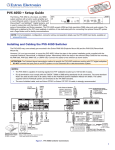
DATA to central server
Chlorine
Pressure
Field
Level
Instruments
GPRS Modem
Valve status
at
Flow
remote
Dynamic IP @ remote
PLC/ RTU
Typical System Architecture
Engineering Station
SCADA Server cum Web Server
Client Operator
Internet
Video Wall
Web Client
Firewall
Communication
Infrastructure
PLC / RTU n
PLC / RTU 1
PLC / RTU…
Hardwired
PLC / RTU 2
Instruments
Hardwired
Instruments
Hardwired
Hardwired
Instruments
Hardwired
Instruments
© Delhi Jal Board
Hardwired
Instruments
Instruments
Page 12 of 193
Central Monitoring System - Request for Proposal – Vol 1
PLC/ RTU Based Monitoring &
Communication Panel
Pressure
Pressure
Transmitter
Transmitter
Flow meter
Server
NICSI
at
Distribution
Mains Line
Typical Field Instrumentation with RTU/ PLC Panel System Architecture
© Delhi Jal Board
Page 13 of 193
Central Monitoring System - Request for Proposal – Vol 1
Convertor / Controller For Water Quality Analyser/s
Water Quality Analyzer
Instrumentation /
Sensor Mounting
Area in Panel
Enclosure
Low
pressure
Pumping
line
from
the
Distribution Main
Line
Plumbing/Valve
Mounting Area in
Panel Enclosure
Typical Physical G.A Drawing for Water Quality Analyser/s Installation in Enclosure at Field Stations
© Delhi Jal Board
Page 14 of 193
Central Monitoring System - Request for Proposal – Vol 1
5. Scope of work
The scope of work shall be in line with the proposed solution mentioned under sr. no. 4.0.
The following outlines the broad areas of scope of work for the Implementing Agency (IA), who is primarily a
System Integrator, and the later sections highlight the detailed scope of work for IA in each of the following
areas. As a broad scope the Implementing Agency will perform the following primary tasks.
a. Procurement, Installation & Commissioning of instruments (flow, pressure, level, water quality etc.),
Hardware, System Software & Networking Infrastructure at all the point of interventions (at various
water works and water distribution network and STPs for data collection)
b. System study and Development of SCADA software based Central Monitoring System covering Alarm
monitoring, MIS Application Development and integration with web services and Role Based Access
Control. MIS reports would be in any suitable format desired by DJB.
c. Trend analysis and data consolidation at Central Data Centre for Dash Board View.
d. Setup infrastructure at Data Centre at NICSI data centre and control room at DJB Head quarter,
Varunalaya.
e. Application Integration with existing SCADA in operation in Water Treatment Plants
f. Training required for the project, covering all the stakeholders
g. Operation & Maintenance of the Overall System Solution (Hardware, SCADA Software, Application
Software and other Infrastructure) for 10 Years from “Go-Live*.
h. Compliance with the SLAs as defined in RFP.
i. Ref. Table 1 for details
© Delhi Jal Board
Page 15 of 193
Central Monitoring System - Request for Proposal – Vol 1
Table-1
Sr.
Service
No.
1 Level
Measurement &
Display
2
3
4
5
6
Type of Instrument
a) Level measuring system per compartment
wise and display on local HMI
b) All required erection hardwares like
cables,trays, fittings, tubes, glands, clamps,
supports etc.
Pressure
a) Pressure Measuring system consisting of
Measurement & Pressure Transmitter display on local HMI
Display
b) All required erection hardware like cables,
trays, fittings, tubes, glands, clamps, supports
etc.
Flow
a) Flow measuring system with display on
Measurement & local HMI
Display
b) All other peripherals required to interface
the flow meter with the system.
a) Residual Chlorine Analyser
b) Turbidity Analyser
Water Quality
c) BOD Analyser
Parameters
d) SS Analyser
Measurement &
All required erection hardware like cables,
Display
trays, valves, fittings, tubes, glands, clamps,
supports etc.
To communicate a) PLC / RTU etc.
with field
b) All required erection hardware like panel,
instruments and cables, trays, fittings, tubes, glands, clamps,
gather the
supports, UPS (for back up supply to local
information &
instrumentation and PLC/ RTU) etc.
data
Software and
database server
for monitoring,
analysis, with
printer etc.
a) SCADA Software, Reporting Application
Software and related Operating system,
database software, application software etc.
b) Integration of existing Water GEMS with
SCADA software and Reporting Application
Software
c) Suitable database server with LAN
connectivity
© Delhi Jal Board
Instrument Functions
a) Monitoring level & Local Indication on HMI
through PLC/RTU
a) Monitoring pressure & Local Indication on
HMI through PLC/RTU
a) Monitoring flow & Local indication on HMI
through PLC/RTU
a) Measure & Indicate on local HMI,
Chlorine concentration, Turbidity, BOD, SS
a) To gather / log information & data from
field instruments
b) To communicate with central system via
GPRS Communication
c) To provide backup supply in case of power
failure through UPS
a) Various graphics / mimic displays / trends,
charts etc. for desired parameters to monitor
water supply system on online basis
b) GPRS telemetry system for communication
with remote sites
c) Communication via SMS and Emails to
concerned staff
Page 16 of 193
Central Monitoring System - Request for Proposal – Vol 1
Ensure the following for the equipment supplied:
•
Commitment of support for spares and services for a period of 10 years from the date of
implementation.
•
System administration and database administration of CMS application for 10 years from “Go-Live”.
•
Customize and implement a proper SLA monitoring tool in consultation with DJB for SLA Monitoring
during O&M Phase.
•
Provisioning of Application Software, Hardware, networking etc. for integration of any intervention
with CMS during Operation and Maintenance Phase.
Instrument scales and displays shall also be based on the basic units listed.
Parameters
Length
Mm
Units
Area
mm
Volume
ml or cc
Time
S
min
H
Day
Mass
Mg
g
Kg
t (tonne)
Temperature
°C
Torque
Nm
Speed
Rpm
spm
ml/s
M3min
mg/s
mbar
mbar
l/s or l/h
M3/h
g/s
Bars
mmH2O
M3/h
Mld or l/hr
kg/m
mm
mmHg
Kg/h
mwc
m
2
2
Remarks
Km
m
Ha
l
m
3
Volumetric flow
-gases
Mass flow
Pressure
Vacuum
Concentration
© Delhi Jal Board
Page 17 of 193
Central Monitoring System - Request for Proposal – Vol 1
- solution
mg/1
%W/V or kg/m3
%W/W
ppm
kg/h
kW
kg/h
kW
A
-gases
Chemical dose
Power
Chemical dose
Power
Current
Voltage
Noise
Frequency
Turbidity
ml/m3
mg/1
W
mg/1
W
mA
V
DB
Hz
NTU
Velocity
m3/hr/m2 or
mm/s
m/hr
Level
MTHD
m/s
meters/min
in case of
Cranes &
m
Reference Standard
Unless otherwise approved instrumentation shall comply with relevant quality standards test procedures
and codes of practice collectively referred to as reference standard including those listed below in
accordance with the requirement detailed elsewhere in this specification.
IEC 60381-1:1982
Analogue signals for process control system Specification for direct current
signals
IEC 60947-4-1:2000
Specification for low-voltage switchgear and control gear contactors and
motor starters. Electromechanical contactors and motor starters.
Specification for low voltage switchgear and control gear. Contractors and
motor starters A.C. semiconductor motor control gear and starters.
IEC 60947-4-2:1999
IEC 60947-43:1999
Specification for low voltage switchgear and control gears. Contactors and
motor starters contactors and motor starters. AC semiconductor
controllers and contactors for non motor loads.
IEC 60770-1:1999
Transmitters for use in industrial process control systems. Methods for
performance evaluation
BSISO 1217:1996
Displacement compressors Acceptance tests
ISO 2112:1990
Specification for amino plastic moulding materials.
ISO 6817:1997
Measurement of conductive liquid flow in closed conduits. Methods using
electromagnetic flow meters
BS EN 837-1:1998
Pressure gauges bourdon tube pressure gauges dimensions metrology
© Delhi Jal Board
Page 18 of 193
Central Monitoring System - Request for Proposal – Vol 1
requirements and testing
BS EN 1057:1996
Copper and copper alloys. Scamless round copper tube for water and gas in
sanitary and heating applications
BS EN 1092-1:2002
Flanges and their joints Circular flanges for pipes valves fittings and
accessories. PN designated steel flanges
BS EN 1563:1997
Founding Spheroidal graphitic cast iron
Specification for degrees of protection provided by enclosures (IP code).
BS EN 60529:1992
BS EN 60534-1:1993
BS EN 60546-2:1993
BS EN 60634:1998
BS EN 60751:1996
BS EN 60873:1993
BS EN 61000-6:2001
BS 89:1990
BS 90:1975
Industrial process control valves industrial process control valves control
valve terminology and general considerations
Thermocouples Tolerances.
Operating conditions for industrial process measurement and control
equipments all relevant parts
Industrial platinum resistance thermometer sensors
Methods of evaluating the performance of electrical and pneumatic
analogue chart recorders for use in industrial process control systems
Electromagnetic compatibility (EMC) Generic standard Emission standard
for industrial environments.
Direct acting indicating analogue electrical measurement instruments and
their accessories all parts
Specification for direct acting electrical recording instruments and their
accessories.
BS 476
Fire tests on building material and structures all parts.
BS 1042-1-4:1992
BS 1041-2-1:1985
BS 1041-2.2:1989
BS 1041-3:1989
BS 1041-4:1992
BS 1123-1:1987
Measurement of fluid flow in closed conduits pressures differential devices
guide to the use of devices specified in sections 1.1 and 1.2
Code for temperature measurement Expansion thermometers Guide to
selection and use of liquid in glass thermometers
Code for temperature measurement Expansion thermometers guide to
selection and use of dial type expansion thermometers
Temperature measurement guide to selection and use of industrial
resistance thermometers
Temperature measurement guide to the selection and use of
thermocouples.
Safety valves gauges and fusible plugs for compresses air or inert gas
installation code of practice for installations.
© Delhi Jal Board
Page 19 of 193
Central Monitoring System - Request for Proposal – Vol 1
BS 1203:2001
Hot setting phenolic and aminoplastic wood adhesives classification and
test method
BS 1553-1:1977
BS 1571-2:1975
BS 1646-1:1979
BS 1646-2:1983
BS 1646-3:1984
BS 1646-4:1984
BS 1794:1952
BS 3680
BS 3693:1992
BS 4675-2:1978
BS 4999-142:1987
BS 5169:1992
BS 5169:1992
BS 6004:2000
BS 7671:2001
Specification for testing of positive displacement compressors and
exhausters methods for simplified acceptance testing for air compressor
and exhausters
Symbolic representation for process measurement control functions and
instrumentation basic requirements.
Symbolic representation for process measurement control
functions and instrumentation specification for additional basic requirements.
Symbolic representation for process measurement control functions and
instruments interconnection diagram.
Symbolic representation for process measurement control functions and
instrumentation specification for basic symbols for process computer, interface
and shared display/control functions
Specification for chart ranges for temperature recording instruments.
Specification for dimensions of temperature detecting elements
and corresponding pockets
Measurement of liquid flow in open channels. All relevant parts.
BS 2765:1969
BS 6739:1986
Specification for graphical symbols for general engineering piping systems
and plants
Recommendations for design of scales and indexes on analogue indicating
instruments
Mechanical vibration in rotating machinery requirement for instruments for
measuring vibration severity
General requirements for rotating electrical machines specification for
mechanical performance: vibration
Specification for fusion welded steel air receivers
Measurement of flow of cold potable water in closed conduits methods for
determining principal characteristics of single mechanical water meter
(including test equipments)
Electric cables PVC insulated non armored cable for voltage up to and including
450/750 V, for electric power, lighting and internal wiring
Code of practice for instrumentation in process control systems installation
design and practice
Requirement for electrical installation. IEE wiring Regulations Sixteenth edition.
© Delhi Jal Board
Page 20 of 193
Central Monitoring System - Request for Proposal – Vol 1
6. Roles & Responsibilities of Implementing Agency
In the CMS initiative of the Department following factors lend to a very unique setting, demanding the need
for focussed strategy at the controlling & operational levels to drive quality and ensure commitment towards
the Project. Implementing agency shall be responsible for the following activities:
1.
2.
3.
4.
5.
6.
7.
8.
9.
Supply and installation of field instruments as finalized with the DJB’s project manager as per the
attached BOQ. The quantities mentioned in the BOQ may vary as per the overall objectives of the
project. The flow and pressure instruments shall be installed using suitable RCC chambers as per site
location instead of directly burying in the ground for ease of maintenance. All cables and accessories
for the purpose shall be provided by the bidder.
Taking over the maintenance of existing flow meters (86 Nos. as in annexure I-B) to ensure their
integration in the system. In case of any deficiency observed during taking over by the successful
bidder the same shall be brought to the notice of the DJB for rectification
All field components (instruments, PLC / RTUs, UPS etc.) shall be installed in protected enclosures as
per the specifications mentioned in the bid documents.
Design, development and implementation of SCADA based CMS including analytical and reporting
tools. CMS shall be installed at the NICSI data center. NICSI data center shall provide the shared
security and other facility like backup and maintenance services. Bidder is required to bear the
expenses for services of NICSI and the same shall be reimbursed at actual by DJB on annual basis. The
connectivity charges between the server at NICSI and the Central Control Room shall be borne by the
bidder for the contract duration. Also all bandwidth, internet and other connectivity rental and usage
charges shall be borne by the bidder for the duration of the contract.
Bidder is required to provide, install and undertake the maintenance of the servers and network
components for the entire duration of the project.
Bidder is required to arrange for communication system from individual equipment ( PLC / RTUs/
Meters) to the Data Center through the GPRS communication service provider, with alternate service
providers to be used as and when needed in case of any disruption in services.
A Control room shall be setup at the DJB Head quarter at Varunalaya. DJB shall provide the space for
the control room. Furnishing the control room as per Control Room Environment shall be the
responsibility of the bidder. Supply & Installation of Video wall and associated hardware/software shall
be responsibility of the bidder. Bidder shall also arrange the communication link from Data Center to
Control room. All communication costs (Dedicated/ GPRS etc.) are to be included in the bid.
It shall be possible to access the CMS reports/status through the web. Role based access enabled CMS
shall be provisioned under the Reporting Application Software.
The bidder shall also have the facility of integrating CMS with a suitable system for mobile alerts (SMS)
in case of alarms.
© Delhi Jal Board
Page 21 of 193
Central Monitoring System - Request for Proposal – Vol 1
Other Key Responsibilities
•
•
•
•
•
•
•
Ensure that the intent and objectives of the project are fully met.
Implementation of CMS shall be as per best practices and process innovations for service delivery in
India and abroad.
It shall ensure appropriate functionality and outcomes for systems developed and implemented.
Shall measure the performance of the system against the defined Service Level Agreement.
Shall monitor and report the non-technical SLAs (e.g. turnaround time for implementation of software
changes, conducting field visits to various locations to measure the solution performance from a
functionality, availability and performance point of view, identification of areas of improvements)
CMS developed under this project is required to adhere to the technical standards and best practices
during design, development, implementation & operations phase.
CMS integrator shall coordinating and implementation of change & capacity building programmes,
process improvement and training for successful implementation of the project.
© Delhi Jal Board
Page 22 of 193
Central Monitoring System - Request for Proposal – Vol 1
7. Detailed Scope of Work
In continuation of the Broad Scope of Work (Sr. No.5), the IA shall also be responsible for meeting of all the
functional and non-functional requirements as listed in subsequent para.
The detailed scope of work is as given below:
A. SCADA Software & Reporting Application Software
•
•
•
Systems Requirement Study for best fit solution & Solution Design
SCADA Software Application Design, Development, Implementation, Training & Documentation
Reporting Application Software Design, Development, Implementation, Training &
Documentation
The IA shall analyze the detailed functional and non-functional requirements as listed in RFP Volume I.
The system requirement specifications shall be prepared by the IA and a Formal sign-off would need to be
obtained from DJB before proceeding with the Design, Development and Implementation of the SCADA
Software and the Reporting Application Software.
System Design
The IA shall design the solution architecture & specifications for meeting the system requirement
specifications finalized by the IA and approved by DJB. The solution design shall include, but is not limited to,
the design of the application architecture, user interface, database structures, deployment architecture,
security architecture and network architecture.
The IA should submit the solution design document to the Department and should obtain the sign off on the
design document before commencing the development of the solution. However, IA shall be responsible for
ensuring the compliance of the end product to the requirements specified in this RFP.
Software Testing
The IA shall perform the testing of the solution based on the approved test plan, document the results and
shall fix the bugs found during the testing. Though the Department is required to provide formal approval for
the test plan, it is the ultimate responsibility of IA to ensure that the end product delivered by the IA meets all
the requirements specified in this RFP. The basic responsibility of testing the system lies with the IA. The
acceptance testing by a 3rd Party agency appointed by the Department as envisaged in this RFP is for the
purpose of certification. Any charges for the same shall be borne by the bidder.
© Delhi Jal Board
Page 23 of 193
Central Monitoring System - Request for Proposal – Vol 1
Training on Application Software
•
•
•
•
The IA is responsible to provide trainings on the CMS Solution. IA is required to train all the
Department users connected with CMS Solution and the designated ones at the Department to
enable them to effectively operate and perform the relevant services using the Application.
The training content will have to be relevant to the target trainees depending upon the role played by
them i.e. processing hands, technical/ administration personnel, supervisors/ managers, and senior
officers.
The IA shall also be responsible for re-training the employees / agencies who are involved in the CMS
solution whenever major changes are made in the system and/or changes happen with personnel
(because of fresh recruitment, promotion, transfer etc) during the full contract period.
The training shall be conducted in full synchronization with the overall Project Implementation plan.
Documentation
The IA shall prepare/update the documents including that of Functional Requirements Specifications, Systems
Requirement Specification, Detailed Design, Test Cases & Results, User Manuals, Operations Manual,
Maintenance Manual, Administrator Manual, and Security Policy as per acceptable standards.
The IA shall obtain sign-off from the Department for all the documents submitted for this Project and shall
make necessary changes as recommended by Department before submitting the final version of the
documents.
B. Data Center
The CMS Solution will be set up on NICSI Data Center.
The IA is expected to prepare a proper plan including BOM and specifications for Hardware, Software and
necessary infrastructure (like Servers, Storage and Networking) for hosting the CMS Solution at Data Centre.
Considering the future growth in CMS applications it is important that IA should plan for the Data Centre in a
manner which will facilitate future expansions in the no. of users. Scalability for each Stakeholder of CMS has
to be planned.
IA will be allowed to provision its Manpower (Physical access) at Data Centre for installation, Configuration and
maintenance of H/W & System Software including OS during the project period, specifically during
Development, testing, user Acceptance testing stage. Such permission would be granted only with due
authorisation of the DJB. Additionally, VPN access for remote administration will be provisioned for the
project.
IA may use the existing Enterprise Management Solution (EMS) facility available at NICSI Data Center or at DJB
as part of RMS project to maintain the service levels of its Data Centre infrastructure. IA should provision
© Delhi Jal Board
Page 24 of 193
Central Monitoring System - Request for Proposal – Vol 1
industry standard EMS for the Application Performance monitoring ( based on real time end user transactions
& application performance measurement), Server & Database Performance Monitoring (Availability &
Performance) and for all the services of the project.
NICSI data centre would provide Rack Space as per the rate applicable for IT infrastructures that need to be
provisioned by IA for the project. For each Rack Space one LAN Switch and one SAN switch would be provided,
as a package.
NICSI / NIC shall provide following product and services at DC sites
•
•
•
•
•
•
•
•
•
Hosting space for DC
Shared SAN storage and tape library back-up from NICSI/NIC as per the sizing requirement by
Bidder
Replication software, Back up Software (File System)
Core Switch, Load Balancer, SAN Switch
Shared firewall and IPS
The power and network will be made available as part of the DC services
The VPN access will be provided for remote administration of server
24x7 Help Desk support to the DJB and its representatives
Connectivity between DC In the event of any collocated hardware related incident, the NICSI/NIC
help desk will inform the personnel identified as Administrator.
Bidder is also expected to provide connectivity to Data Centre from its GPRS/ other service provider and to DJB
HQ. In such case bidder will ensure that all necessary components to extend the desired connectivity to the
control room is included in the bid.
Bidder shall include all the components (other than mentioned above) that are required to make the solution
complete.
•
Bidder shall design a suitable replication strategy and an effective model for replication of the
databases on the SAN storage.
© Delhi Jal Board
Page 25 of 193
Central Monitoring System - Request for Proposal – Vol 1
Primary Server
Standby Server
Client Operator
Internet
Video Wall
Web client
Communication
Infrastructure
Static IP @ central SCADA
GPRS/GSM
Fig: Schematic for central location
Expectation from Bidder for DC
•
•
•
The installation, configuration and maintenance of system softwares and application will be the
responsibility of the Bidder
The maintenance of Bidder’s hardware colocated at NICSI will remain Bidder’s responsibility
Bidder needs to be get security audit of the Application before moving the application to
production environment. The application may be audited by the list of companies for the said
purpose at CERT-in website. Any charges for the same shall be borne by the bidder.
Assessment, Procurement and Installation of IT Infrastructure, field instruments
IA shall assess the infrastructure requirements (including Servers, Storage, Networking and Security) for
operationalization of the CMS system and to provide the functionalities to all the stakeholders, in full
conformity with the SLAs.
Important: All system software licenses would have to be taken in the name of the Department.
For all software products it is necessary for bidders to certify that proposed infrastructure shall be sufficient to
meet the performance requirements and have provision for future scalability requirements of the project.
Addressing any performance issues / degradation during O & M phase shall be the responsibility of IA at no
additional cost other than what is specified in the commercial proposal.
Procurement of IT Infrastructure and field instruments
The IA shall procure & supply the IT Infrastructure for the system as proposed by them in their technical
proposal. The IA shall ensure that all the equipment supplied to the Department is brand new and is free from
any defect of any sort.
© Delhi Jal Board
Page 26 of 193
Central Monitoring System - Request for Proposal – Vol 1
IT Infrastructure and field instruments Installation
The IA shall be responsible for operationalization of the CMS system from end to end, which includes
installation of IT Infrastructure, field instruments, ensuring capturing real time process data and connecting to
the CMS databases. The IA shall deploy the application software at the Data Centre and shall ensure that the
application software services are made accessible to the CMS solution users.
Connecting all locations on the CMS solution network
The IA shall connect all the field locations, point of intervention on CMS solution network to the Data Centre in
line with the architecture and specifications and shall ensure that the access to
CMS portal is provided to all the users. The scope of work for IA also includes procurement of necessary
Internet bandwidth for hosting the CMS Portal and to provide access for the Stakeholders to the relevant
functionalities.
Warranty
The IA shall provide comprehensive warranty for 3 years & subsequent Maintenance support for a period of 7
years (total of 10 years) for all components supplied for the CMS system as per the contract.
The IA shall repair / replace any parts / components of the CMS Infrastructure supplied for this project if the
components are defective and during the entire warranty period IA shall apply all the latest patches/updates
for all the software components after appropriate testing.
Documentation
The IA shall undertake preparation of documents including that of Infrastructure solution design &
architecture, configuration files of the Infrastructure, user manuals, Standard Operating Procedures,
Information Security Management procedures as per acceptable standards.
The IA shall take sign-off on the documents, including design documents, Standard Operating Procedures,
Security Policy & Procedures from DJB and shall make necessary changes as recommended before submitting
the final version of the documents.
C. Operations & Maintenance of entire CMS system environment
The IA shall be required to provide operational and maintenance services for CMS system including, all the
software and hardware components. This section discusses the Operations & Maintenance services to be
provided by IA with respect to SCADA softwrae, Application Software & supporting IT Infrastructure
Management and field instruments at the intervention points.
Operations & Maintenance of Application Software
© Delhi Jal Board
Page 27 of 193
Central Monitoring System - Request for Proposal – Vol 1
Maintenance includes, but is not limited to production monitoring, troubleshooting & addressing the
functionality, availability & performance issues and implementing the system change requests.
The IA shall keep the application software in good working order; meeting the requirements defined by the
Department, perform changes and upgrades to applications as requested by the Department, within the
overall scope of the quality and quantity of functionalities to be delivered under this RFP.
The following is the broad scope for maintenance and support functions with regard to the software:
•
•
Compliance to the Functional Requirements specified in Volume I of the RFP
Compliance to Service Levels specified in RFP.
The IA shall ensure compliance to uptime and performance requirements of CMS Solution as indicated in the
SLA in RFP Vol 3 and any updates/major changes to the software shall be accordingly planned by IA for
ensuring adherence to the SLA requirements.
Application Software Maintenance
The IA shall rectify all the errors/bugs/gaps/ modification on account of rule/acts/policy change of Government
in the functionality offered by CMS solution at no additional cost during the operations & maintenance period.
Software Change & Version Control
All planned changes to application systems shall be coordinated within established Change Control processes
to ensure that:
•
•
•
Appropriate communication on change required has taken place
Proper approvals have been received
Schedules have been adjusted to minimize impact on the production environment
The IA shall define the Software Change Management & Version control process and obtain approval for the
same from the Department. For any changes to the software, IA has to prepare detailed documentation
including proposed changes, impact to the system in terms of functional outcomes/additional features added
to the system. IA is required to obtain approval from the Department for all the proposed changes before
implementation of the same into production environment and such documentation is subject to review at the
end of each quarter of operations & maintenance support.
Maintain configuration information
Maintain version control and configuration information for application software and any system
documentation
IT Infrastructure, field instruments Maintenance & Operations
© Delhi Jal Board
Page 28 of 193
Central Monitoring System - Request for Proposal – Vol 1
•
•
•
•
Overall monitoring and management of the systems implemented for CMS in the data Centre,
which includes administration of Data Center Infrastructure (Web/application servers, database
server, and storage), Network and all other services ancillary to these facilities to ensure
performance and availability requirements of the Project.
Ensuring compliance to the uptime and performance requirements, including data backup for
CMS Solution as indicated in the RFP.
Perform the patch management, testing and installation of software updates issued by the
OEM/vendors from time to time. These patches/updates before being applied on the live
infrastructure of the data Centre shall be adequately tested. Any downtime caused due to updates
& patches shall be to the account of the IA and it shall not be considered as ‘Agreed Service DownTime’.
Ensure overall security of the solution including installation and management of Antivirus solution
for protection of all the servers and systems implemented for the project, application of
updates/patches etc. The antivirus patches have to be updated and applied from time to time,
after appropriate testing of the patches in the staging area.
D. Field Instruments Design Requirements
Instruments mounted in field and on panels shall be suitable for continuous operation. All electronic
components shall be adequately rated and circuits shall be designed so that change of component
characteristics shall not affect plant operation.
Apparatus mounted in panels shall be suitable for continuous operation at the maximum internal panel
temperature expected in service and due account shall be taken of heat given off by other equipment.
All electronic components shall be adequately rated and circuits shall be designed so that change of
component characteristics shall not affect performance. In the selection of solid state equipments,
special consideration shall be given to the effects of heat and the need for artificial cooling. The air
temperature range within which such apparatus is designed to operate without effect on performance
shall be stated.
All I&C equipment shall be new, of proven design, reputed make, and shall be suitable for continuous
operation. Unless otherwise specified, all instruments shall be tropicalised. The outdoors equipment shall be
designed to withstand tropical rain. Wherever necessary space heaters, dust and waterproof cabinets shall be
provided. Instruments offered shall be complete with all the necessary mounting accessories. All instruments
should be designed for ambient temperature of 50 Deg Centigrade.
All instruments of submersible type shall be protected to IP-68 of IS: 13947, Part-I.
Unless otherwise stated, field mounted electrical and electronic instruments shall be weatherproof to IP65 of 15:13947 Part-I.
The degree of weather protection for panel mounted instruments shall be IP-52 of 18:13947, Part-I.
Field cabinets and enclosures shall be IP55 gasketed with multi-point latching doors.
© Delhi Jal Board
Page 29 of 193
Central Monitoring System - Request for Proposal – Vol 1
All the instrumentation to be supplied under this contract for measuring flow, level and pressure,
residual chlorine, water pH, turbidity, energy , rpm, vibration etc. shall be of robust design, inherently
free of faults and requiring as little maintenance and adjustments as possible for effective and reliable
operation.
Instruments, supports etc. are all to be of materials resistant to or protected from the temperature and
humidity to be encountered in the atmosphere present in the tropical climate.
The unit of flow meter shall be in litres/sec. and the integration shall be in cubic metres. Ranges shall be
selected to show normal plant operation between 50% and 75% of the full scale reading.
Instruments are to be of a type which will maintain reasonable accuracy without adjustment. Normally
accuracy shall be within plus or minus 1% of the full scale deflection throughout the full range of
measurement, unless otherwise specified.
All necessary sensors, transmitters / converters, PLC / RTUs, indicators, cabling, etc. for the
instrumentation system shall be provided as required by the manufacturer.
Instruments shall be provided with mounting hardware and floor stands, wall brackets, or instrument
racks and all necessary accessories as per site requirement.All work shall be in strict accordance with
codes and reference standards as described above.
Unless otherwise stated, overall accuracy of all measurement system shall be ±1% of measured value, and
repeatability shall be ±0.5%.
Unless otherwise specified, the normal working range of all indicating instruments shall be between 30%
and 80% of the full scale range.
The instruments shall be designed to permit maximum interchangeability of parts and ease of access
during inspection and maintenance.
The field instruments i.e. the instruments mounted outside the control panel shall be mounted at a
convenient height of approximately 1.2m above grade platform.
Lockable enclosures shall be provided for the field mounted instruments.
All field instruments and cabinet/panel-mounted instruments shall have tag plates/ name plates
permanently attached to them.
All wetted parts of the sensors shall be made of non-corrosive material capable of working with chlorine
content of 5 ppm.
© Delhi Jal Board
Page 30 of 193
Central Monitoring System - Request for Proposal – Vol 1
The performance of all instruments shall be unaffected for the ±10% variation in supply voltage and ±5%
variation in frequency simultaneously.
The transmitters shall be provided with on-line test terminals. Zero and span adjustments shall be
provided for all instruments.
Access ladders/ platforms shall be provided for maintenance and operation of all instruments.
Local indicators shall be provided for each sensors, and other primary device.
On return of power after an electrical power failure, all instrumentation and controls shall function
automatically without any reset action required by personnel. The Contractor's attention is drawn to the
requirements of installations which require to be "FAIL SAFE".
Test Equipment
Test equipment shall be provided, together with items such as instruction manuals, carrying / storage
cases, unit battery charger where applicable, special tools, calibration fixtures, cord extenders, patch
cords and test leads, which are not specified but are necessary for checking field operation of equipment
supplied under this Contract.
1.5.1
1.5.2
1.5.3
One hand held pressure calibrator
One portable (DMM) digital multi-meter with rechargeable battery and charger
and test leads, and carrying-case.
One toolkit consists of screw driver, testers etc.
Instrumentation Circuit Routes
Signal cables shall not be run in the same conduits or duct as power cables. Installation in rigid G.I. Class
B Pipe / MDPEconduit or steel trunking shall be provided wherever required in view of site conditions .
Signal cables which are not completely enclosed in G.I. Class B Pipe / MDPE conduit shall be separated by
at least the necessary distances as per norms from LV power cables and HV cables.
All cables running from the field instruments to the PLC / RTU panel shall be a single, Continuous length,
without joints, except at marshalling boxes. The boxes shall have terminal blocks with 20 percent spares
in addition to terminals for all wires including spare wires. Special care shall be exercised to carry
earthing lines through marshalling boxes and control panels.
Installation
Instrumentation and necessary equipment shall be installed in accordance with the manufacturer's
instructions. The locations of equipment shall be determined in the field. Exact locations shall be
© Delhi Jal Board
Page 31 of 193
Central Monitoring System - Request for Proposal – Vol 1
approved by the DJB during construction. Contractor shall furnish all labour and materials necessary to
complete the work in the approved manner.
All piping to and from field instrumentation shall be provided with necessary unions, test tees, couplings,
and adaptors.
Brackets and hangers required for mounting of equipment shall be provided. They shall be installed in a
workmanlike manner and not interfere with any other equipment.
The screen on each process instrumentation cable shall be continuous from source to destination and be
earthed as directed by the manufacturer of the instrumentation equipment but in no case shall more
than one earth point be employed from each screen.
Tests
Test plan shall be submitted for approval as part of the project plan. Furnish the services of the
servicemen, all special tools, calibration equipment and labour to perform the tests. Certified copies of
the tests shall be furnished in duplicate to the DJB .
Following installation, check-out and final adjustment of all the instruments, a performance check shall
be made on each. All status and alarm switches as well as all monitoring and control functions shall also
be checked. Each device installed must be signed -off by the DJB as acceptable. Testing shall be done
from the signal source to the final element or device including all field wiring.
If, during running of the tests, one or more points appear to be out by more than the specified amount,
adjustments or alterations shall be made as necessary to bring equipment up to specification
performance. Following such adjustment, the tests shall be repeated for all specified points to ensure
compliance.
© Delhi Jal Board
Page 32 of 193
Central Monitoring System - Request for Proposal – Vol 1
8. GENERAL CONDITIONS FOR WORK
01]
Engineer / Engineers-In-Charge:
The term shall mean the person or firm appointed by the owner, who is authorized representative to
undertake the duties and powers assigned to the Engineer by the DJB and by these specifications acting
directly or through authorized representative. The contractor will be notified in writing the name of the
Engineer which shall generally be the Executive Engineer or Project Management Consultant appointed
by DJB, New Delhi.
02]
Engineer's Representative:
The term means any resident engineer or assistant to Engineer, appointed by the DJB or the Engineer to
perform the duties set forth by engineer.
03]
Tenderer:
A person or association of persons, firm, DJB or Organization submitting tender for the work.
3.1] Contractor:
Is the person or partnership of persons, firm or DJB or organization identified as such in the contract
agreement and is referred throughout the contract documents, as if, singular in number and masculine in
gender. The tern contractor means the contractor or his authorized representative.
04]
Contract Documents:
The contract document consist of the contract agreement, the notices, the instructions, the contractor's
tender, the tender security, work order, the bonds, the drawings, the specifications and the agenda.
05]
Contract Agreement:
The contract agreement represents the entire and integrated agreement between the parties hereto
and supercedes all prior negotiations, representations or agreements either written or oral.
5.1] Acquaintance with Site and Work Conditions etc.:
The contractor shall study the site and general conditions in respect of approaches, labors, Water
Supply, climate, quarries and the data included in the tender papers, get it verified from the actual
inspection of site etc. before submitting the tender. In case of doubt about any item or data included in
the -tender or otherwise, it shall be got clarified in pre-tender conference. Once the tender is accepted, it
© Delhi Jal Board
Page 33 of 193
Central Monitoring System - Request for Proposal – Vol 1
shall be -concluded that the contractor has verified and made himself conversant -with all the details
required for completing the work as per conditions and specifications.
Contractor shall make his own arrangement for approaches, roads for conveyance of materials etc., No
extra claims shall be entertained due to non availability to such roads, approaches, for conveyance of
materials equipments.
5.2] Machinery Required :
All machinery required for executing the work shall be arranged by the contractor. Department shall not
take any responsibility for providing such machinery, even on rental basis. No concreting shall be
permitted unless centering and reinforcement is approved by the engineer in charge.
5.3] Supervisory Staff:
The contractor shall have a well qualified experienced resident Engineer, who will be well versed with
design and installation aspect of Instrumentation, PLCs and all allied electro-mechanical works, to be in
day to day charge of the work and he shall be authorized to receive instructions from the Engineer-incharge, of the work .Instructions and orders given to the resident Engineer shall be deemed to have
been given to the contractor. For this purpose the contractor shall communicate to the department,
name, qualifications and experience of such Engineer to be appointed for execution of the work.
06]
Program of Execution of Work :
The contractor shall furnish in duplicate, to the Engineer in charge within fifteen days from the date of
issue of work order a program indicating close progress of work to be achieved for completion within
tendered time limit. The whole work is to be executed in such a manner so that regular pumping is not
affected. In case shut down is necessary, prior permission from Engineer in charge shall be necessary.
Intimation for shut down shall be well in advance i.e. not less than 10 days. Necessary care shall be
taken to minimize the period. The progress schedule shall be in the form of bar charts, statement,
forms, periodical out turn of quantities. Should the program be found defective in any respect or
impracticable, the same shall be modified as required. Should the actual progress of work lag behind at
any stage, revised program by accelerating the progress to be achieved shall be drawn up keeping the
target of completing the scheme unaltered.
07]
Bill of Quantities:
The Bill of quantities shall contain items of the Works relating to each component of the scheme to be
carried out by the Contractor
The Bill of Quantities will be used to calculate the Contract Price. The contractor shall be paid for the
quantum of work done at the rate mentioned for each item in the Bill of quantities.
© Delhi Jal Board
Page 34 of 193
Central Monitoring System - Request for Proposal – Vol 1
08]
Change in the Quantities:
If the final quantity of the work done differs from the quantity in the Bill of Quantities for the particular
item/ items, the rates as in the agreement for the relevant items shall be paid as per the actual quantity.
DJB is not bound for the consumption of all the items given in bid document.
09]
Additional Items:
All items are to be included in the price bid. However, payments for any additional item identified after
signing of contract which is not mentioned in the bid, shall be finalized based on the market rates with
due approval of Engineer – in -charge.
10]
Tools and Plants:
All tools, plants and equipments required for this contract will be arranged by the Contractor at his own
expense. The Contractor shall erect necessary construction plant as may be necessary and shall use such
methods and appliances for the proper performance of all the operations connected with the work
brought under the contract ensuring satisfactory quality of work and maintenance of the programme
schedule. The non availability of any tool, plant or equipment shall not be relied upon as a reason for
non- functioning or slow progress
11]
Information and Data:
The information and data made available to the contractor in respect of the works and site conditions
are only general and the contractor is advised to get himself fully acquainted with the nature of the
location of the works and the surroundings, quarries, local conditions and such other aspects that are
relevant to the works.
12]
Coexistence with other Contractors:
Where two or more contractors are engaged on work in the same vicinity, they shall work together
harmoniously with the spirit of cooperation and accommodation. The contractor shall not disrupt or
disturb the works or labour arrangements of the neighboring contractors. In case of disputes and
difficulties arising between the contractors in the execution of the respective works, the Engineer in
charge shall interfere and give directions for the smooth functioning of the entire works and it shall be
the bounden duty of the contractors to abide by these instructions
13]
Right of Way and Facilities:
The Contractor shall bear all costs and charges for special or temporary rights of way required by him in
connection with access to site. The Contractor shall also provide at his own cost any additional facilities
outside the Site required by him for the purposes of the Works
© Delhi Jal Board
Page 35 of 193
Central Monitoring System - Request for Proposal – Vol 1
14]
Drawings and Design Submitted With the Tender:
Acceptance to the tender shall not mean approval to design or P & I drawing, enclosed by the tenderer
while submitting his offer. All tender, drawings will be treated as tentative. Deficiencies if any found a
from a functional, technical and departmental obligatory requirement, points of view shall have to be
rectified and made good in detailed working drawing as pointed out by DJB without any extra claim.
The tenderer shall submit detailed Specifications for the Instrumentation, PLC / RTUs, and softwares
including all required accessories. Reference of I.S. and/or other authoritative literature with extract of
relevant parts signed by the tenderer shall be submitted by the tenderer in support of other factors
considered in specification and design calculations. He shall submit detailed working drawings like P & I
diagram, Instrumentation diagram, wiring etc. for each unit. Detailed specifications of each
instrumentation, PLC / RTUs, and communication systems in triplicate shall be submitted to the
Executive-Engineer
14.1] The design, supply, install, testing, training & commissioning of the various instrumentation shall be
based on prevailing relevant I.S. as specified and equivalent British, German or American standards,
recognized reference books, and shall be as per, standard Engineering code of practice, and shall be such
as, to meet functional, technical, structural and aesthetic requirements.
14.2] Any modification, alteration in design, calculations and detail drawings, to be carried out as a result
of compliance of scrutiny, remarks of the competent authority, shall be carried out and submitted a
fresh, by the contractor, if called upon to all above concerned authorities in the manner indicated in (I)
above without claiming any extra cost.
14.3] The actual execution of work shall be started by the contractor only after receipt of the technical
approval to the above work plan, detailed design drawings, specifications etc. from the competent
authority.
14.4] Normally a period of about 30 days would be required for scrutiny of, and getting approval of the
competent authority, to the design and detailed drawings from the date of receipt from the contractor.
The contractor shall be fully responsible for the delay that would be caused in scrutiny of and giving
approval to the design and drawings due to their being incomplete, shabby and haphazard manner,
without illustrative dimensioned sketches in the design and due to non submission of extracts of
reference books (duly signed by tenderer) called for. No extra time limit shall be granted on account of
reasonable time required in carrying out the scrutiny as mentioned above by the department and due to
improper designs and drawings submitted by the contractor.
© Delhi Jal Board
Page 36 of 193
Central Monitoring System - Request for Proposal – Vol 1
15. Responsibility of Contractor for Design Drawing & Work:
Even-though the design and drawings are approved by the competent authority, the Contractor shall be
fully responsible for the technical and arithmetical correct-ness and soundness of the design plan and
drawings and for the safety of works executed on the basis of such approved design and drawings and
to the damages or failure of the works. It shall have to be done by the contractor entirely at his cost.
16. Discrepancies and Omissions:
The tender drawings and specifications shall be considered as explanatory, of each other and together
shall form the technical requirements and stipulations of tender documents. Detailed drawings shall
have preference over small scale drawings. Similarly detailed specifications shall have preference over
general specifications. Should any discrepancy arises to the meaning, intent or interpretation of any
specification or drawing the decision of the Engineer in charge shall be final and binding on the
contractor.
17. Inspection-And Testing:
All instrumentation, PLC / RTUs, etc. complete irrespective, whether specified or not, shall be tested at
manufacturer's works calibration check and test certificates for all the instrumentation shall be furnished
along with testing procedures followed. Tests shall be witnessed by the Third party and certificate for
the same shall be submitted to DJB.
Cost for all such tests including all incidental expenses shall be borne by the contractor and cost for all
such tests shall be deemed to have been included in the tendered rates.
18. Factory Test, Site Test and Fee:
The Contractor shall make all necessary arrangements for to and fro travels for DJB Engineers/Officers
for pre-delivery inspection in India and Abroad. The entire traveling cost including ticketing, boarding
and lodging of the members of the DJB team shall be borne by the Contractor as per RBI Guideline(for
overseas visit) and no claim, whatsoever on this ground, shall be entertained by the Engineer-in-Charge.
The Contractor shall keep a provision in the programme for 4 weeks notice for inspection in India and 12
weeks notice for testing/inspection overseas."
19. Fees Payable to Third Party:
All fees payable to Third Party for inspection and testing (factory and site) shall be borne by the DJB.
Date for such inspection will be fixed by the contractor ' in consultation with Engineer-in-charge.
The Third party testing does not relieve the contractor of his liability for satisfactory performance of
equipment and in such case the defective equipment shall have to be replaced by the contractor without
any extra cost.
© Delhi Jal Board
Page 37 of 193
Central Monitoring System - Request for Proposal – Vol 1
20. Quality of Material and Equipments:
All Instrumentation- PLC / RTUs, software, etc. complete shall be of best quality confirming to relevant
Industry / International standards. All mechanical, Electrical & other Instrumentation shall be of
approved makes, best quality and of CE, UL mark only, where available & acceptable. These shall be got
approved from the Engineer-in-charge before erection and use.
21. Cost of Repairs:
Loss or damage to the Works or materials to be incorporated in the works between the Start Date and
the end of the Defects Liability periods shall be remedied by the Contractor at the Contractor's cost if the
loss or damage arises from the Contractor's acts or omissions
22. Change in Site Alignment or Orientation or Modification:
No compensation shall be paid on account of change in site, alignment or orientation of the proposed
work. The department reserves the right to modify the layout, design and any part thereof, if considered
necessary.
23. Water for Construction etc.:
The contractor shall make his own arrangement, at his cost to get water for construction. Department
shall Issue only recommendatory letters in this respect, if requested by the contractor in writing.
24. Electric Power Supply:
Electric power supply required by the contractor for the purpose of execution of work and installation of
instrumentation shall have to be arranged by himself at his cost and department shall not take any
responsibility in this respect, except giving recommendatory letter.
25. Use of Sites:
The contractor shall specifically keep the department informed about the temporary
sheds/accommodation done by him at site of work; where on the NAME BOARD of company/ contractor
shall be fixed. No unauthorized persons/vehicles shall be allowed there unless otherwise required for
execution of works.
The responsibility of the temporary sheds, their occupants, their safety/dismantling when done with,
shall be the contactor's liability. Excavated materials shall be the property of the department and will be
disposed off as per directions of Engineer-in-charge.
26. Foundations:
Foundations shall be designed considering bearing capacity and as approved by the department.
© Delhi Jal Board
Page 38 of 193
Central Monitoring System - Request for Proposal – Vol 1
27. Tender to Be Strictly According to Tender Conditions & Specification: And Pre-Tender Conference :
It should be clearly noted, that the tenderer has to strictly comply with the conditions and specifications
laid down in the tender and no variation or deviations are permissible. The basic principles mentioned in
the specifications and conditions of the tender shall be retained. On no account variations in conditions
and specifications shall be carried out.
28. Accidents on the Work :The contractor shall be fully responsible for any accident that may occur to the labour on his work on
duty and report the same to the Enqineer-ln-Charge and concerned Government Authority and shall pay
all necessary compensation as per rules, failing which it would be paid by the department and the same
shall be recovered from the contractor with interest.
29. Rate Inclusive Of All Taxes Duties etc. :
All the taxes and duties such as S.T./C.S.T., turn over tax/sales tax on works contract, Octroi, excise duty
etc., levied by the State and Central Government and local bodies at prevailing rates applicable on the
date of receipt of tender shall be fully borne by the on contractor and shall not be reimbursed to him on
any account. The tender rates quoted by the contractor for the items shall be taken as inclusive of all
such taxes and duties. Tax concession / exemptions if any available for the project, Contractor shall be
responsible to obtain the same, on behalf of DJB , New Delhi which shall transfer all the concessions to
the Contractor, only after actual receipt of concession. DJB shall not be responsible for delay or nonreceipt of concession from respective Governments, Departments for what so ever reasons.
30. Trial Run, Commissioning of the system:
On completion of trial run, commissioning of all equipment shall be taken up. Commissioning period shall
be of 4 weeks. During commissioning, the contractor shall be responsible to deploy all required qualified,
skilled and unskilled personnel full time to operate, maintain and repair the equipments.
Final inspection shall be conducted after 4 weeks of trial run and commissioning, for satisfactory
performance of the system and same shall be recorded & inspected by the team of three Officers of DJB
and project management consultant appointed by DJB.
31. Income Tax:
Income tax 'as per applicable on gross value of each bill shall be deducted toward income tax and a
certificate to that extent shall be issued by the Engineer-in-Charge.
32. No Interest on Dues:
© Delhi Jal Board
Page 39 of 193
Central Monitoring System - Request for Proposal – Vol 1
No interest shall be payable by the Department on the amounts, due to contractor's pending final
settlement of claim.
33. Completion of the Works:
The completion and delivery of the works shall be deemed to be full, complete and sufficient only when
the Engineer in charge accepts the same and issues a certificate in writing viz. " Certificate of Completion
" under the hand of the Engineer in charge to the effect that all the works contracted for and directed to
be executed have been completed and are in a sound, satisfactory, workmanlike and complete and
usable condition and the contractor has in the opinion of the Engineer in charge reasonably fulfilled and
completed his contract and undertaking except so far as it relates to the operation and maintenance of
the works as hereinafter provided.
34. Record Drawings and Designs :
After satisfactory completion of the work in all respect, the contractor shall submit five sets of designs
and completion record drawings of each and every work as actually constructed with all dimensions and
levels with the stamp 'Record Drawing' along with the specifications, operating manual and instructions
etc., before finalization of the final bill without claiming any extra cost, failing which the final bill shall not
be paid. The circuit diagrams of panels, layout, details of spares, makes, addresses, phone no. of firms
shall also be given with illustrative technical literature of manufacturers.
© Delhi Jal Board
Page 40 of 193
Central Monitoring System - Request for Proposal – Vol 1
9. Functional Overview of Central Monitoring System (CMS)
This section presents the indicative Functional Overview of CMS based on SCADA & Reporting Application
Software with brief description of each application/services planned to be implemented through CMS.
Figure 1: Central Monitoring System Services
It may be specifically noted that Supply and implementation of GIS is not part of this RFP. GIS scope is limited
to the integration of the CMS with existing/proposed GIS system at DJB.
The services of the department, both information and transactional, shall be delivered to the stakeholders
through multiple service delivery channels including portals (for both internal and external stakeholders,
mobile communication (SMS services).
For all users / stake holders the portal is envisaged to deliver information services about the processes and
allow to control based on authorization and access rights. The portal shall also facilitate transactional services
both for water delivery and energy use.
The portal shall be accessed through secure intranet and all services shall be delivered through the internet.
The access shall be extended through secure VPN connectivity.
© Delhi Jal Board
Page 41 of 193
Central Monitoring System - Request for Proposal – Vol 1
The proposed system shall also provide the mobile application/SMS services for facilitating communication for
alarm / alerts /intervention required.
Surveillance System
The Water Distribution Surveillance system through Business event Identification services, including
Geographical Information System (GIS), shall enable capturing, tracking of information on the incidence,
prevalence, and spread of functional deficiencies and enable the department for effective planning for
controlling / removing such deficiencies. The system shall support fault mapping, which shall enable
understanding the geographical distribution and spread of fault in the past or present. In summary, these
services module will provide effective MIS on the over all system status across the distribution network both in
textual and graphical form, to enable DJB staff and the senior management for effective planning of supply
and distribution water and optimize energy usage.
Integrated Intelligence System Service
This will provide a comprehensive “Management Information System” which will maintain and provide critical
information such as the Water Distribution Infrastructure, Supply & Distribution related information,
Information about the maintenance & operation, available staff, nearest E & M centre and so on which will
essentially create an effective mechanism to monitor and administer the provision of preventive E & M
services. Since all the information from the different systems would get collated at a central place, department
officials and staff would be able to query the system for various kinds of intelligence analytical information,
thus enabling the Department to take critical decisions as well as to plan for the future.
Some of the key features of this intelligence system will be to incorporate;
Multi-Dimensional Analysis
•
•
•
•
•
•
•
•
•
Data elements can be automatically highlighted (via font, weight, colour changes) based on userdefined criteria (e.g. show data field in red when Distribution% falls below 50%)
Various Graphical displays should be available so that the information can be represented to different
stakeholders. This should then also have ability for drill down to the lowest level of data capture.
Saving of query/report output as a snapshot for future use.
Triggering of another process based on preset conditions. (I.e. if a report is run and a specific figure
goes above 80% trigger another report and notify a supervisor).
Security access levels are applicable to reports and also enforceable with respect to report
distribution.
Audit capabilities, including logs of user activity.
Ability to encrypt communications between the user and the data source (server). (I.e., software
supports Entrust PKI)
System should provide ability indicate Key System indices at all levels. E.g. WTP, UGR, BPS etc.
One of the important factors coming out of the System should be the trend analysis. Trends like
outages happening in a particular command area at a specific time etc will help the officials to take
decisions proactively for the betterment of the delivery system.
© Delhi Jal Board
Page 42 of 193
Central Monitoring System - Request for Proposal – Vol 1
•
•
•
a)
b)
c)
d)
e)
f)
After the generation of the report the next thing is the distribution of the information to the key
stakeholders. The ability to send a section of a report to a particular group of users is an important
feature incorporated in the system. It should be able to define collaborative workgroups consisting of
a subset of users. Within such workgroups, end-users should be able to publish and share their reports
and views. The delivery of these reports should be decided by the stakeholder E.g. Dashboard, email
or wireless device and also how the report should be delivered. E.g. HTML, PDF, TXT, etc.
System should generate alert if exceptions are identified in the report and deliver the alert to
dashboard or email or mobile device of the concerned user.
The BI platform must be a comprehensive and integrated suite of Analytical tools designed to bring
greater business insight to broadest audience of users allowing them to have web based self service
access to relevant and actionable intelligence from relevant data sources (of which they have access
to :
Ad Hoc Query Capability: BI Platform must provide an analytical tool enabling a web based ad-hoc
analysis tool where end user can interact with logical view of information creating charts, pivot tables,
reports, gauges, dashboards etc
Save and Share Capability: After end user spends time and creates, adds, deletes, changes the pivot
table views, he/she should be able to save these changes and share the updated view with group of
users.
Dashboard Capability: End users should interact with BI platform using rich, interactive, role based,
easy to understand web based dashboard providing access to live reports, prompts, charts, tickers,
pivot tables and graphics.
Multi Channel Report Publishing Capability: BI platform should provide a scalable reporting server
capable of generating richly formatted reports from multiple sources (SQL server, Oracle, Informix,
Sybase, Files, XML,URL), in multiple formats (Word, Excel, RTF, PDF and XML) published on multiple
channels ( email, webdav, print, ftp to file server).
Disconnected Analytics Capability: Increasingly officials are using laptops in their daily operations. The
BI platform must provide an ability to download the dashboard (reports and data) on the laptop hence
enabling users to work even when they are not connected to network.
The BI platform must enable the data centre to single, consistent logical view of information across
different department specific operational systems, warehouses and multi dimensional sources. This
will ensure that business user has unified view of all accessible information.
•
•
Data capture and control
o
Integrate wide range of sensors
o
Move data intelligently
o
Execute local commands
o
Run distributed operational logic
Manage distributed device infrastructure
© Delhi Jal Board
Page 43 of 193
Central Monitoring System - Request for Proposal – Vol 1
•
•
o
Discovery of devices and sensors
o
Remote configuration of devices
o
Monitoring
o
Security
Event processing and services
o
Complex event processing
o
Stream processing
o
Services including data aggregation, geographic information, identification and
association, condition, command and permission, and persistence
Process integration
o
Extend existing systems and enable new business processes
o
Monitor business processes
o
Provide information to people
Short Messaging Services
UIE applications need to have a SMS (Short Messaging Service) for the different stakeholders to get
information from the UIE application. Officials will be using the SMS to get information of System healthiness
central applications. The following will be functionalities required for the SMS gateway applications.
There should be an integrated SLA based policy enforcement engine. It will allow the UIE system to
dynamically customize the data and access rules to fit capacity of the network nodes. Also the administrators
can use the traffic management and shaping capability to increase the service and reliability
10. SCADA & Reporting Application Software
The task of the SCADA shall be to collect all process-related data from the processing units into the process
database. The process database shall reflect the real-time image of the process. The collected information
shall further be distributed, e.g. for displays, historical archiving, calculations, printing, reports generation and
further transmission to other systems.
CMS shall primarily provide the following functions:
© Delhi Jal Board
Page 44 of 193
Central Monitoring System - Request for Proposal – Vol 1
•
Continuous system self supervision
•
Display of events & alarms
•
Storage of time stamped events
•
Trend reports
•
Display of station Network Diagram with status of all process objects.
•
Alarm and event reports
•
Automatic printout of fault reports
•
Parameter settings of event & alarm.
CMS system should be capable of being configured to various predefined users so that each user defined in
the system can be given access rights for various features. The hierarchies of authorization shold take due
care of protecting the system from unnecessary configuration changes. The Suggested users are following
but not limited to
•
System Administration
•
Engineering
•
Maintenance
•
Operation
The access rights shall be in the form of passwords & user ID both, Only the system administrator should be
authorized to add / remove users and change access rights. It is desired that the system should prompt the
password change after first log-in so that default password will be overwritten.
It is desired that the CMS software should support multiple instances of software on the same personal
computer simultaneously of the same make. It is desired that the software should have the functionality to
alert the system operator about the event in a specific station by pop up or colour change of the minimized
software instances for a particular station
A feature of sending the SMS message to field crew is also desired. It shall able to send disturbance & fault
event to the field crew. The CMS shall possess the following additional functionality.
•
•
•
Features to add new graph, display& reports
features of web view only access
Data exporting to other system in the XML format.
11. FUNCTIONAL REQUIREMENTS OF THE SYSTEM(CMS):
System Display:
© Delhi Jal Board
Page 45 of 193
Central Monitoring System - Request for Proposal – Vol 1
The Display system should be based on the principle of communicating to the operator through visual aids like mimics/
screen videos like Single line diagrams of individual distributors
The operator should be able to use pictures to communicate with the process and the control system:
•
Pictures should visualize the controlled process with industry standard symbols and Specified
colors
•
The operator should be able to select the object by using the mouse and issuing the command by
double click. The operator should also able to issuing the command on selected object by using
the functional keys. The keys should be standard for all the installation of a specific manufacturer.
•
Pictures should inform the operator about alarms and events by specified color changes
•
Pictures should illustrate process data.
Trends Display:
A trend is
are:
•
•
•
•
•
•
•
•
•
a time-related follow-up of process data. The major parameters to be considered for trends
Flow
Pressure
Turbidity
Energy
Chlorine levels
Ph
Ammonia
Water Levels
BOD, SS/SS
The trend display shall be available in graphical mode as a line graph. Trends shall be available on a two
dimensional co-ordinate system that consists of horizontal time (X) axis and vertical value (Y) axis. Trends
shall have minimum following characteristics
The curve can be scrolled in both direction, X and Y.
The time axes shall be scaleable on minute, hours , day and monthly basis
a) it should be possible to get the value of parameters at any instance by clicking the trend .
b)
minimum eight parameters trends should be visible in one screen at one point of
time sharing the same process data
c) The graphic window shall be resizable & maxim sable.
Report Display:
© Delhi Jal Board
Page 46 of 193
Central Monitoring System - Request for Proposal – Vol 1
The system shall collect the data from the database and able to produce report & produce printout on the
operators request. The system shall have the capability of displaying minimum 10 reports on a single window
simultaneously The system shall able to generate reports based on the user selected values on the basis of
time interval of Day/ Week/ Month/ Year
However system should be capable of generating reports on the basis of
• Predefined time intervals
• when a predefined event occurs
• Day (mean, peak)
• Month (mean, peak)
• Year (mean, peak)
System should provide functionality to produce user defined reports
Event List
The event list presents the process events from the monitored process in pre defined way whenever there is
change in status or change in limiting values. Each event shall normally be presented by displaying a predefined
event text line, which describes the event in the process. Event text lines shall consist of a time stamp, object
identification, a single text indicating status and data value. The events should be printed with WTP/UGR ID,
Distributor ID & equipment wise segregation. The events shall be presented in chronological order so that the
latest event appears on the top line of the first page. The event list shall contain keys for browsing the list
forward and backward. Configured of event log file for day, week, month and year wise shall be possible.
Events shall be stored in the history buffer in the computer’s RAM memory, and also stored on the computer
hard disk. The length of the history may be 10,000 events. The 10000 events shall be stored on the basis of
First in First out Principle (FIFO). User configurable prioritization of event shall be possible. The system should
have the functionality for user configurable prioritization & filtration of events.
Alarm List
The alarm list shall display the present alarm situation of the supervised process. All data Acqusition & control
malfunctions including no responses from field devices and Check- back –verification errors on control
selections, should be reported as alarms. Each alarm message should clearly indicate the type of malfunction
that caused the failure in the operation sequence. Each alarm shall have the time stamp (date & time), object
identification (WTP name & Distributor name), a signal text and a text indicating alarms status. The alarms will
be shown in chronological order. Alarms will have different colors on the basis of priority and operator shall be
in apposition to view in archives categorywise. Occurrence of alarm will be noticed by popup in screen with
sound. Alarm sound will be different on the basis of priority. The alarm data can be exported to external
system as per the requirement of the operator.
System Level Functions
1. Status Supervision
The position of each equipment shall be supervised continuously. Every detected change of position shall be
immediately displayed in the single-line diagram on the station CMS screen, recorded in the event list, and a hard
copy printout shall be produced. Alarms shall be initiated in the case of spontaneous position changes.
© Delhi Jal Board
Page 47 of 193
Central Monitoring System - Request for Proposal – Vol 1
The positions shall be indicated by two auxiliary switches, normally closed (NC) and normally open (NO), which
shall give ambivalent signals. An alarm shall be initiated if these position indications are inconsistent or if the time
required for operating mechanism to change position exceeds a predefined limit. The CMS shall also monitor the
status of auxiliaries. The status and control of auxiliaries shall be done through separate one or more IED and all
alarm and analogue values shall be monitored and recoded through this IED.
2. Measurements
Analogue inputs shall be connected via PLC / RTU with/without intermediate transducers. The measured values
shall be displayed locally on the station CMS and in the control centre. The abnormal values must be discarded.
The analogue values shall be updated every 10 minutes.
Threshold limit values shall be selectable for alarm indications.
3. Event and Alarm Handling
Events and alarms that are generated, by the IEDs, or by the sensor unit shall be recorded in an event list in the
station CMS. Alarms shall be recorded in a separate alarm list and appear on the screen. All, or a freely
selectable group of events and alarms shall also be printed out on an event printer. The alarms and events shall
be time-tagged
4. Presentation and Dialogues General
The processor shall be a redundant with hot standby and shall provide basic functions for supervision and
control of the equipments. The operator shall give commands to the equipments on the screen via mouse
clicks or keyboard commands.
The CMS shall give the operator access to alarms and events displayed on the screen. Aside from these lists on
the screen, there shall be a printout of alarms or events in an event log.
The following standard pictures shall be available from the CMS:
Single-line diagram showing the status and measured values Control dialogues with interlocking and blocking
details. This control dialogue shall tell the operator whether the device operation is permitted or blocked.
Measurement dialogues Alarm list, station / bay oriented Event list, station / bay-oriented System status
5. CMS Design Principles
Consistent design principles shall be adopted with the CMS concerning labels, colours, dialogues and fonts. Nonvalid selections shall be dimmed out.
The object status shall be indicated using different status colours for: Selected object under command
Selected on the screen Not updated, obsolete values, not in use or not sampled Alarm or faulty state
Warning or blocked Update blocked or manually updated Control blocked Normal state
1. Process Status Displays and Command Procedures
The process status of the WTP/Distribution System in terms of actual values of analog as well as the positions of
valves, circuit breakers, motors, pumps shall be displayed in the WTP single-line diagram.
In order to ensure a high degree of security against undesired operation, a "select-before-execute" command
procedure shall be provided. After the "selection" of a switch, the operator shall be able to recognize the
© Delhi Jal Board
Page 48 of 193
Central Monitoring System - Request for Proposal – Vol 1
selected device on the screen, and all other equipments shall be blocked. As communication between control
centre and device to be controlled is established, the operator shall be prompted to confirm the control action
and only then final execute command shall be accepted. After the “execution” of the command the operated
switching symbol shall flash until the switch has reached its new position.
The operator shall be in a position to execute a command only, if the equipment is not blocked and if no
interlocking condition is going to be violated. The interlocking statements shall be checked by the interlocking
scheme implemented at bay and WTP level.
After command execution the operator shall receive a confirmation that the new switching position has been
reached or an indication that the switching procedure was unsuccessful with the indication of the reason for
non-functioning.
7. System Supervision & Display
The CMS system shall be comprehensively self-monitored such that faults are immediately indicated to the
operator, possibly before they develop into serious situations. Such faults are recorded as a faulty status in a
system supervision display. This display shall cover the status of the entire WTP and Distribution Network
including all sensors, IEDs, communication infrastructure and remote communication links, etc.
8. Event List
The event list shall contain events that are important for the control and monitoring of the WTP/Distribution
System. The event and associated time (with1 ms resolution) of its occurrence has to be displayed for each
event. The operator shall be able to call up the chronological event list on the monitor at any time for the whole
WTP/Distribution System or sections of it. A printout of each display shall be possible on the hard copy printer.
The events shall be registered in a chronological event list in which the type of event and its time of occurrence
are specified. It shall be possible to store all events in the computer for at least one month. The information shall
be obtainable also from a printed event log.
9. Alarm List
Faults and errors occurring in the WTP/Distribution System shall be listed in an alarm list and shall be immediately
transmitted to the control centre. The alarm list shall substitute a conventional alarm tableau, and shall
constitute an evaluation of all station alarms. It shall contain unacknowledged alarms and persisting faults. The
date and time of occurrence shall be indicated.
The alarm list shall consist of a summary display of the present alarm situation. Each alarm shall be reported on
one line that contains:
The date and time of the alarm The name of the alarming object A descriptive text The acknowledgement
state.
Whenever an alarm condition occurs, the alarm condition must be shown on the alarm list and must be displayed
in a flashing state along with an audible alarm. After acknowledgement of the alarm, it should appear in a steady
(i.e. not flashing) state and the audible alarm shall stop. The alarm should disappear only if the alarm condition
has physically cleared and the operator has reset the alarm with a reset command. The state of the alarms shall
be shown in the alarm list (Unacknowledged and persistent, Unacknowledged and cleared, Acknowledged and
persistent).
Filters for selection of a certain type or group of alarms shall be available as for events.
© Delhi Jal Board
Page 49 of 193
Central Monitoring System - Request for Proposal – Vol 1
10. Object Picture
When selecting an object such as a valve or other equipment in the single-line diagram, the associated bay
picture shall be presented first. In the selected object picture, all attributes like Type of blocking Authority
Local / remote control etc., shall be displayed.
11. Control Dialogues (In future)
The operator shall give commands to the system by means of mouse click located on the single-line diagram. It
shall also be possible to use the keyboard for command activation. Data entry is performed with the keyboard.
Dedicated control dialogues for controlling at least the devices shall be available:
12. User-Authority Levels
It shall be possible to restrict activation of the process pictures of each object (bays, apparatus...) within a
certain user authorisation group. Each user shall then be given access rights to each group of objects, e.g.:
Display only Normal operation (e.g. open/close) Restricted operation (e.g. by-passed interlocking) System
administrator
For maintenance and engineering purposes of the station CMS, the following authorisation levels shall be
available:
No engineering allowed Engineering/configuration allowed Entire system management allowed
The access rights shall be defined by passwords assigned during the log-in procedure. Only the system
administrator shall be able to add/remove users and change access rights.
13. Reports
The reports shall provide time-related follow-ups of measured and calculated values. The data displayed shall
comprise: Trend reports:
•
•
•
•
•
•
•
•
•
Day (mean, peak)
Month (mean, peak)
Semi-annual (mean, peak)
Year (mean, peak) Historical reports of selected analogue
Values:
Day (at 15 minutes interval)
Week
Month
Year
It shall be possible to select displayed values from the database in the process display on-line. Scrolling
between e.g. days shall be possible. Unsure values shall be indicated. It shall be possible to select the time
period for which the specific data are kept in the memory.
Following printouts shall be available from the printer and shall be printed on demand:
i.
ii.
iii.
Daily voltage and frequency curves depicting time on X-axis and the appropriate parameters
on the Y-axis. The time duration of the curve is 24 hours.
ii. Weekly trend curves for real and derived analogue values.
Printouts of the maximum and minimum values and frequency of occurrence and duration of
© Delhi Jal Board
Page 50 of 193
Central Monitoring System - Request for Proposal – Vol 1
iv.
v.
vi.
vii.
viii.
maximum and minimum values for each analogue parameter for each circuit in 24 hr period.
Provision shall be made for logging information about breaker status like number of operation
with date and time indications.
Equipment operation details shift wise and during 24 hours.
Printout on adjustable time period as well as on demand.
Printout on adjustable time period as well as on demand.
Reports in specified formats which shall be handed over to successful bidder.
14. Trend Display (Historical Data)
It shall be possible to illustrate all types of process data as trends - input and output data, binary and analogue
data. The trends shall be displayed in graphical form as column or curve diagrams with a maximum of 10 trends
per screen. Adjustable time span and scaling ranges must be provided.
It shall be possible to change the type of value logging (direct, mean, sum, or difference) on-line in the window.
It shall also be possible to change the update intervals on-line in the picture as well as the selection of threshold
values for alarming purposes.
15. CMS (Human Machine Interface)
The VDU shall show overview diagrams (Single Line Diagrams) and complete details of the network with a
colour display. All event and alarm annunciation shall be selectable in the form of lists. Operation shall be by a
user friendly function keyboard and a cursor positioning device. The user interface shall be based on WINDOWS
concepts with graphics & facility for panning, scrolling, zooming, decluttering etc.
16.1 Software Requirements
CMS Software
CMS software can be divided into three categories:
a) Operating system software
b) Application software that includes any application loaded on the computer (SCADA Software )
c) Configuration file(s) for the settings, displays, and database of the CMS application (Reporting
Application Software
Note that the CMS computer may have other applications that also have configuration files.
The CMS application typically runs on computers requiring the latest version of Windows, Linux, or some other
operating system. Design tradeoffs can occur when certain requirements are made. For example, the
Designer/Specifier may require a certain operating system to meet a corporate standard, which may limit CMS
selection. The behavior of the operating system software during and after power failures may help to prevent
unexpected CMS performance and must be determined prior to deployment.
© Delhi Jal Board
Page 51 of 193
Central Monitoring System - Request for Proposal – Vol 1
In addition to the CMS software, the Designer/Specifier should also consider other software applications to be
loaded on the computer. Examples of such applications include software that configures WTP/Distribution
System devices, monitors network traffic, retrieves data from WTP/Distribution System devices, views
different files, web browsers, and other applications that may be important to personnel working in the
WTP/Distribution System. These applications may or may not be directly linked in the CMS application.
The Designer/Specifier should also consider whether the actual configuration files should have backup files
located on the WTP/Distribution System computer or if the files should be stored elsewhere. Due to availability,
security, and redundancy, this determination may not be trivial and should engage all of the impacted parties.
Issues:
Patches and updates to all CMS software will be issued at various times during the life of the system.
Coordination of the various updates is essential and may require a maintenance contract or licenses that the
Designer/Specifier should include in the CMS specification. This may increase software costs. The
Designer/Specifier may require that all vendors provide copies of all CMS software. The Designer/Specifier
should consider whether multiple copies are required, which may increase software costs due to licensing
issues. The Designer/Specifier should also address process issues that most likely should not be included in the
CMS specification. The Designer/Specifier should provide a means to provide a version control process that
records all CMS software. These records should include compatibility relationships between the various
software (which versions inter-operate as a complete CMS system). A backup process should also be put in
place.
1.SCADA Software Specifications:
1. Architecture
The SCADA architecture shall provide the following:
•
•
•
•
•
•
•
•
Client / Server architecture based on TCP/IP networking and report-by-exception (RBE) technology
Standalone single server operation.
Symmetric main-standby & capacity for triple standby server functionality.
Additional servers for client load sharing and remote locations.
Permanent Standby Server designed to be placed outside corporate firewalls providing a read-only
access to the server while ensuring corporate security.
Fully automated data transfer between servers to provide complete server redundancy. This transfer
shall include configuration, real-time data, historic data and event lists. Database updates shall be on
an incremental basis with tuneable parameters
A scalable fully distributable architecture providing:
– Unlimited number of server systems.
– Unlimited number of display clients.
Where multiple servers are deployed, the system shall be capable of being configurable from a single
client.
© Delhi Jal Board
Page 52 of 193
Central Monitoring System - Request for Proposal – Vol 1
•
•
•
•
•
•
•
All redundancy shall be handled by the database, with the operational state of systems preserved
through a server changeover. The system shall not rely on driver redundancy for data transfer when
providing redundant server. The system shall present a uniform view of data including communication
status after a fail over.
Forced changeover between main and standby allowing seamless changeover between main and
standby servers without shutting down either server.
Clients to connect to a synchronizing server as soon as the configuration and current data in the
database has synchronized. Incomplete data sets as per clients request on event or trend provide
indications that the synchronization is still in progress to ensure that conclusions are not drawn from
incomplete data sets.
Configurable compression of data communications between client/server and server/server to allow
optimisation of communications performance over WAN networks.
Change reporting on Client/Server and Server/Server links rather than polled communication to permit
operation on WAN networks.
Capable of operating Client/Server and Server/Server links over low to medium speed channels
depending upon database size.
Application shall be native 32-bit and 64-bit versions and supported on Windows® Server and
Workstation operating systems including Windows 2000, Windows XP, Windows 2000 Server,
Windows 2003 Server, Windows 7 (32 and 64 bit) and Windows Server 2008 R2 and later.
2. Database
The SCADA database shall be of true relational database design and optimized for real-time SCADA operation.
The database shall be object oriented and organized in a hierarchical structure. It shall support user-created
“Templates” that allows management of common configuration from a single point in the database. Instances
of templates shall be used for repetitive, standard configuration.
Templates of standard configuration shall support multiple object types including, but not limited to:
• Point / Tag objects
• PLC / RTU or PLC / RTU objects
• Mimics or Graphic display objects
• Trend objects
• Logic programs
• Schedules
• Link objects
The SCADA database shall allow users to extend the database schema to store custom data, in either the
configuration or data stream. These changes can be performed online without need for server restart.
3. Operator Interfaces
•
SCADA software shall provide the ability to support multiple local and remote display clients.
© Delhi Jal Board
Page 53 of 193
Central Monitoring System - Request for Proposal – Vol 1
•
•
•
•
•
•
•
•
•
•
Display facilities shall be available via LAN, WAN and dial-up connection.
Display clients shall be supported as Rich Clients without the requirement of a database resident at the
display node.
Rich Clients shall support database management and configuration changes.
Rich Clients shall support multiple monitors (multi-head display), allow logon for all heads from a single
location. The system should also provide navigation facilities such that displays on each head can be
controlled from any head. (yoking)
Integrated Web Sever capability shall be available, providing all display and operational facilities of the
Rich Client without the need for additional software to be installed.
Web Clients shall allow users to view Mimics, Trends, Database Objects, Reports as well as perform
control functions using a standard web browser.
Changes made to the SCADA server shall require no additional steps to be performed in order for
those changes to be available to Rich Clients and Web Clients.
Each full function Rich Client shall be configurable to connect to one, or multiple server systems
Full function display clients shall automatically fail-over & reconnect to a redundant server node when
server change-over occurs.
Current generation Windows® look and feel shall be provided by the SCADA system operator
interfaces, including provision for “favourites lists” comprising links to any server object. This includes,
but is not limited to: Mimics, Graphs, List Queries
4. Mimics / Graphics
SCADA system Mimics shall support a wide range of graphical facilities. Scalable Vector Graphics are required in
order to permit operation of the SCADA system with different resolution clients operating simultaneously.
Fixed resolution bitmap graphics are not acceptable.
Mimics shall be multi-layered, object oriented and permit mimics to be embedded in other mimics. Other
objects that must be available for embedding in a mimic include:
• Button objects
• Hyperlinks
• Disk images (e.g. JPG, motion JPEG)
• Remotely updated images
• Hyperlinks with embedded queries (for generating filtered lists directly from a mimic)
• Object menus
Graphical facilities within a mimic must also be object oriented including the ability to manipulate attributes of
embedded objects in real time, supporting animation including but not limited to:
•
•
•
•
Fill factors
Fill colour
Rotation
Position
© Delhi Jal Board
Page 54 of 193
Central Monitoring System - Request for Proposal – Vol 1
• Line thickness
• Text attributes
• Transparency
• Alpha blending
• Multi-rate Flashing
A suite of Graphical Symbols shall be provided for integration with configuration templates and embedding
within other mimics.
Import of mimics shall be supported from DXF format, including integration of multi-layered DXF drawings in
to native SCADA mimics.
Adding Custom database fields dynamically to Metadata where the server does not have to be restarted after
adding or modifying.
Mimics shall support the ability to specify OPC data source information to display directly on the mimic. This
permits data from other systems to be seamlessly integrated in to the SCADA display.
Other facilities required to be supported by mimics includes:
• Context sensitive object menus available from mimic
• Accept an alarm from a mimic
• Issue a control from a mimic
• Operator Notes (as a native feature)
• ToolTips
• Hyperlinks to external documents (e.g. HTML, PDF, MS Office® suite documents)
Objects embedded and displayed on any mimic shall be viewable through both the full function client and web
client displays.
5. Start-up
The SCADA system shall startup unattended, and without compromising system security. The SCADA server
process shall operate as a Windows® Service. The SCADA server shall start without the requirement for an HMI
client to start. Windows® logon shall be available prior to display client staPLC/ RTUp which must provide
additional security.
Shutting down a display client (including on the server node) shall not affect other users or the server.
Administrative privilege shall be required to shutdown a SCADA server.
6. Configuration
The SCADA software shall provide full seamless On-line configuration of all database parameters including but
not limited to:
– Communication channels
© Delhi Jal Board
Page 55 of 193
Central Monitoring System - Request for Proposal – Vol 1
– PLCs and PLC / RTUs
– Points / Tags
– Sequences
– Schedules
– Alarm redirection
– Mimics / Graphics
– Trends/graphs
– Reports
Configuration changes shall be capable of being made from local and remote workstations using Rich Clients,
with appropriate privilege. Configuration changes are to be applied to the Main SCADA server and seamlessly
applied to Standby server and other SCADA server nodes such as user performance sharing SCADA nodes.
Further, configuration changes made to mimics and other display objects shall be immediately available to
local and remote Rich and Web display Clients without any manual intervention. Changes should be updated
automatically in local caches where appropriate. This facility shall be a native feature of the product and not
require external scripts or customisation.
All aspects of the look and feel of the SCADA system, including default field values, shall be configurable. It is
not acceptable for colour regimes, communication parameters and other aspects of the system to be hardcoded.
It shall be possible to add user defined fields to the SCADA database. These fields should be accessible both
internally and externally to the SCADA system; being exposed via OPC, ODBC, OLE Automation, XML/SOAP,
etc.
The SCADA server shall provide detailed diagnostics concerning its internal operation. The diagnostics shall be
available through capture to a log file as well as online locally on a server and remotely via Telnet and Web
interface.
The SCADA software shall provide the ability to perform a complete audit trail of all database changes down to
the individual property level of objects to ensure complete system integrity and safe system operation. These
details shall be provided as a built-in integrated part of the system and shall include, but not be limited to the
following:
• Time of change
• Object on which change was performed
• Property of the object that was modified
• Property value before and after the change
• User that made the change
• Reason for the change
© Delhi Jal Board
Page 56 of 193
Central Monitoring System - Request for Proposal – Vol 1
Stored configuration records should be maintained in the historic database for a configurable time period,
support redundant SCADA server configurations and allow access from standard database interfaces such as
queries and simple mechanisms for displaying and filtering the configuration records
7. Alarm Management
The alarm system shall provide facilities where actions can be triggered by alarms. These facilities shall be
provided as a built-in integrated part of the system and shall include, but not be limited to the following:
– Configuration criteria for alarm actions
– Escalate Alarm priority
– Delivery of alarm to users via SMS
– Delivery of alarm to users via E-mail
– Trigger other actions including sequences
Integrated paging facilities shall be provided without the need for additional software. The paging facilities
shall include calendar operation for roster based user lists with flexible interface for reconfiguration of alarm
management.
Tracking of alarms shall provide as a minimum:
• Alarm activation including point name, state, timestamp, priority
• Alarm de-activation
• Alarm acceptance including time, user responsible, optional comment
• Custom alarm fields for display of additional or operations specific information
Where a full function Rich Client is connected to multiple SCADA systems, alarms from all systems shall be
combined and filtered, based on user privilege and areas of responsibility.
System administrators shall be able to configure user accounts with default filters so tha operator alarm lists
can be confined for users to those areas where they assume responsibility.
Full function Windows & Web clients shall provide indication of alarm condition, with the ability to change
alarm tone, color, and other attributes based on alarm priority.
Full page and window display of the current alarm list to be shown. It shall also be possible to modify the
background color of alarm lists.
Alarm display, acceptance, query and comment entry shall be available via an integrated product Web
interface.
Alarm limit time profiles allowing analog setpoint levels to vary over the course of a day to account for
conditions at the site.
Consequential alarms to allow one (or more) alarms to be suppressed as the result of another alarm occurring.
Suppressed alarms will be received and processed by the SCADA Server and recorded in the event journal for
© Delhi Jal Board
Page 57 of 193
Central Monitoring System - Request for Proposal – Vol 1
future auditing, however the operator shall not be forced to take an action on an alarm where the cause is
known.
8. Event Journal
The system shall provide, as a built in feature and without the requirement for custom or external software,
facilities for event logging. These facilities shall be separate from the alarm list and include the capability to
insert user comments at any place in the event list.
Event lists shall be obtainable through an SQL-like query or filtered through user entry on a forms-based
display.
Event data is to be stored in a time-series relational database. Each event record shall comprise a timestamp,
responsible user, point name, message, and reason for event log.
The event journal shall support the following:
– ODBC / SQL interface to event data
– Filter and browse via full function display client
– Filter and browse from Web client interface
9. Historical Data
The SCADA system shall provide a built in data historian with the following facilities as standard features.
These shall be provided without the addition of external software modules:
•
•
•
•
Time-series relational database
ODBC / SQL interface to historical (trend) data
Historical data to be stored with time-stamp, point quality, alarm status
Historic storage is to be based on configurable criteria including time between samples, alarm state
change
• Compression capability
Historical files supporting fixed interval sampling only will not be accepted.
Where historic data can be retrieved through communication devices such as PLC / RTU/PLC / RTUs, the
historic data sub-system shall natively provide the capability to backfill this data in to the historian.
No loss of data or gaps in data as a result of communication or server failure shall be accepted. The vendor
must demonstrate its ability to ensure data integrity and history data recovery.
An API shall be included to provide interface capability with the SCADA database. This shall be based on OLE
Automation and/or .NET
© Delhi Jal Board
Page 58 of 193
Central Monitoring System - Request for Proposal – Vol 1
The historic data subsystem shall provide fixed and user configurable views of the historic data tables. These
views are required to provide SQL pre-processing and present historic data in aggregate format.
The SCADA server shall provide Historian functions including the capability to validate historic data prior to
exposing it externally to the SCADA system, selectable archiving rates, point-by-point storage compression
regimes, annotation on history samples for tracking comments on operational conditions, modification of
historic data for normalization and correction (tracks previous value and modifying user and is subject to user
privilege), auditing of modified or annotated history.
10. System Security & Access
The SCADA system shall provide a high level of inherent security. To this end the SCADA software shall provide
security access down to data point level, and support individual Users, User Groups and a matrix of system
capability and access to any level of the SCADA database.
Full function Rich & Web client interfaces shall require explicit administrative configuration to valid connection
to the SCADA server.
Web interface facilities shall provide the capability to operate the Web interface using SSL and encrypted data.
The Web functionality shall be provided in an integrated way with the web server facility tightly coupled with
the SCADA database. It is not acceptable for the system to utilize IIS or similar external web interfaces, or
require web pages to be “published” from the SCADA system. Changes in configuration to the SCADA system
shall not require additional steps in order to provide modified information to the SCADA Web interface.
The SCADA system security shall provide the ability to be integrated with Windows domains to authenticate
logon attempts against a trusted domain. Validation should occur across all client interfaces, ensuring that
users utilizing all types of clients are subject to the built in system security policies.
11. Open Connectivity
To provide easy access for customized reports and external data manipulation the SCADA software shall
provide inherent OPC and ODBC database connectivity without the need for additional software options or
modules. Integration with desktop Microsoft products is essential.
The following Open interfaces shall be provided as integrated components of the SCADA system are required:
•
•
•
•
•
OPC Data Access (OPC-DA) to the SCADA server real-time and configuration database
ODBC and OLE-DB to the SCADA server real-time database, historian, event / parameter journal and
configuration database
OPC Historic Data Access (OPC-HDA) to historian
OPC Alarm & Event (OPC-AE) to event sub-system
OLE Automation interface to the SCADA server database
© Delhi Jal Board
Page 59 of 193
Central Monitoring System - Request for Proposal – Vol 1
12. Reports
An integrated reporting package shall be able to generate, print and export reports:
• Triggered by SCADA events
• On user demand
• On timed schedules
Report generation shall use latest technology in database access and be capable of combining data from
multiple databases via ODBC/SQL. This shall include SCADA and non-SCADA databases.
Reports shall be able to be generated in a number of formats including:
• HTML for viewing via Web interface
• PDF format
• CSV format
• MS Office® suite format
Generated reports shall be able to be:
•
•
•
•
viewed in Rich Clients and Web Clients
printed on a local or network printer
stored on disk file, locally or remotely
e-mailed to assigned users
13. Standard Drivers
The SCADA system shall provide native support for fully integrated Wide Area SCADA PLC / RTU protocols.
This shall include the capability for supporting all protocols in redundant SCADA server configurations and support
redundant communication paths.
All drivers shall provide the ability to monitor communication statistics, log driver diagnostics, and provide online
access to driver and channel diagnostics remotely via Telnet or similar mechanism. Captured diagnostics shall be able
to be translated to HTML for analysis in clear human-readable format.
Apart from PLC / RTU and PLC / RTU communication drivers, the system shall also support as standard the
following drivers:
• SMS (with TAP and UCP service) to mobile phones and pagers with a GSM or CDMA modem
connected directly to the SCADA server.
• – a full function system is required including calendar based rosters
• SNMP – monitoring of network devices such as routers, computers, UPS, etc.
• NTP – time server monitoring and alarming
• ODBC – query data from other databases
• Windows Performance Monitoring
• OPC-DA driver
PLC / RTU Protocol Support
© Delhi Jal Board
Page 60 of 193
Central Monitoring System - Request for Proposal – Vol 1
Wide area PLC / RTU protocols shall support:
•
•
•
•
•
•
•
•
local serial port communication
terminal server serial port communication
Ethernet LAN communication via TCP and UDP ports
time synchronisation
presetting output configuration points where configured
fully integrated incorporation of events from a PLC / RTU
unsolicited exception reporting
Where PLC / RTUs utilise the DNP3 communications protocol, those devices must support the DNP3
Secure Authentication standard.
All drivers shall support capability to update SCADA database point value / alarm state / point quality /
timestamp. PLC / RTU protocol drivers shall support the ability the backfill time-stamped data into Event Logs,
Historic Data to maintain data integrity in the event of communication failure.
The driver architecture shall support user accessible interfaces to access major driver functions. This shall
include, but not be limited to:
• enable / disable PLC / RTU communications
• trigger an integrity poll
• alter communication parameters
Drivers shall maintain current state of target device information, and when used in redundant server
architecture shall retain state information and be able to receive solicited and unsolicited information from the
PLC / RTU immediately following a server transition. It is not acceptable for the system to indicate
communication failure or not be able to receive communication from a remote device during the period of
transition from one server to another.
The following protocols shall be supported and integrated with the product:
•
•
•
•
•
Modbus Master serial protocol
Modbus Slave serial protocol
Open Modbus/TCP Master protocol
Open Modbus/TCP Slave protocol
OPC-DA client driver (for connection to OPC Server driver)
The OPC-DA interface shall include as a minimum, integration with SCADA database value / state / quality /
timestamp data, support OPC-DA 1.0 and 2.0 specification interfaces, polled and exception modes, tag
browsing.
Logic
© Delhi Jal Board
Page 61 of 193
Central Monitoring System - Request for Proposal – Vol 1
The SCADA system shall support logic sequences with full access to all SCADA system services at run time.
Programming of sequences shall be to the IEC61131-3 international standard and support as a minimum the
following languages:
•
•
•
•
Ladder Diagrams
Function Blocks
Structured Text
Sequential Function Charts
Sequences shall be able to me modified and started and stopped online. Sequence changes shall be a native
part of the database and replicated to redundant SCADA servers.
Special scripting languages to perform the control strategy will not be accepted.
12. PLC / RTU :
The PLC / RTU shall provide
•
•
•
•
•
•
Functionality to map the field devices
Provide communication connectivity to the all the slave devices through Serial Communication or TCP/IP
communication.
Provide a communication facility to the field devices through serial communication through RS232 port via a
serial communication device viz. modem etc.
Should have a ability to collect data from all connected devices, regardless of protocol and make it available
to the control centers & CMS using a LAN,WAN connectivity.
Should act as a protocol translator to ensure interoperability with the protocols defined in the
communication principle section.
Should be capable of handling real time data exchange services to publish or subscribe information for
defined master and slave protocols.
Specifications for PLC / RTU
The PLC / RTU shall be non redundant, modular.
The controller shall at least include the following base I/O and further expansion shall be possible using
expansion modules
The PLC / RTU shall be as per the following specifications:
Digital Inputs: 16 (24 VDC)
Digital outputs: 10 (24 VDC Transistor/ Relay)
Analog Inputs: 8 (Min.12 Bit resolution)
Communication ports: 3 Nos. One for HMI, One for Connecting Energy Meters (MODBUS) and one for
MODEM/ Router.
© Delhi Jal Board
Page 62 of 193
Central Monitoring System - Request for Proposal – Vol 1
The CPU specifications shall be as follows:
Basic CPU:
a) Communication Ports: 1 Programming Port, 1 CANopen/Profibus Port & 2 Auxiliary Ports (Protocol
configurable)
CANopen/ Profibus/ Eq. Network: Max 31 Nodes (Up to 500 mtr)
Max. Units per Node: 1 Base + 3 Expansion Units
Baud Rate: Auto Baud Detection (10, 20, 50, 125, 250, 500, 1000 Kbps)
b) Operating Temperature: 0 to 550 C
c) Memory capacity: More than 16 K steps of programming.
d) Memory cassette: Shall have facility to install Flash/ EPROM cassette.
e) SCAN time: Better than 2 micro second per general Boolean instruction.
f) Relative Humidity: 5 to 90% Non-Condensing.
g) Noise Immunity: IEC 61000-4-4
h) Shock: IEC61131-2 Operating: 15g (DIN rail & Panel Mounting)
i) Vibration: IEC61131-2 Operating: 5 to 150 Hz, 1g, 3.5mm Amplitude
j) Mounting: DIN rail or Panel Mount
k) Protection: IP 20
l) Network Connections: 5-pin 5.08 mm Pitch Screw Type Open Style Connector
m) Unit Power Supply: 11 to 30 VDC Through 5-pin
n) Network Power Supply: 24 VDC, 5 A
o) Power Supply Protection: Reverse Polarity
p) Digital Inputs: 24 VDC, Sink/ Source selectable. With Input current less than 16mA.
q) Digital Outputs: Relay having capacity 230 VAC, 5A. (Optionally interposing relays can be supplied).
r) Analog Inputs: 4-20 mA or 0-10 VDC selectable with A/D conversion of min 12 bits.
s) All cards in PLCs shall be weatherproof coated.
LOCAL HMI for PLC/ RTU
© Delhi Jal Board
Page 63 of 193
Central Monitoring System - Request for Proposal – Vol 1
The purpose of Local HMI is to indicate current status of the level, pressure, flow, energy data and water
quality etc.at the field stations.
The HMI shall also act as an aid to facilitate Pop up alarms, enter time delays, and operate the necessary
equipment. The HMI shall have 1 printer port and 1 USB port as a minimum.
The HMI shall be Touch screen with minimum diagonal screen size of 6”
Programming Software:
The programming software shall allow downloading of Relay Ladder Logic and/or standard C++ programs
from within one package. The software shall allow the user to develop and download the application and
system configuration over communication network via radios, Ethernet, leased and dial-up lines.
The PLC / RTU shall allow Ladder and/or C++ applications to run concurrently. Any failure in the Ladder
application shall not affect other applications.
The Relay Ladder Logic shall include the following functions:
Data logging function with time & data
Modem dialing and control.
Timers, counters, mathematical functions, memory functions.
Standard Ladder Logic functions such as coils and contacts.
Boolean logic functions.
Bit transfer functions.
Block transfer functions.
Scaling function
Totalizing function
Flow function
On-line monitoring of Relay Ladder Logic power flow shall be included to facilitate start-up and debugging
of programs.
Relay Ladder Logic program shall be up to 12K words in size, with no fixed limit on the number of
networks.
The programming software shall support on-line monitoring and forcing of any register in the protocol
database when utilizing the built-in protocol. Forcing shall write a value to the register and prevent
modification of the register content by the communication protocol or the application software. A global
command
to
remove
all
forcing
must
be
included.
In addition to forcing, the software shall be capable of writing a value to any register in the protocol
database but continue to allow the protocol or application software to modify the contents of the register.
The unit must also support IEC 61131-3 programming using Sequential Function Chart (SFC), Functional
Block Diagram (FBD), Ladder Diagram (LD), Structured Text (ST), Instruction List (IL), Flow Chart (FC)
languages using a separate programming tools.
Data Logging Functionality
The Controller shall support Data Logging via Removable USB Mass Storage devices which include:
© Delhi Jal Board
Page 64 of 193
Central Monitoring System - Request for Proposal – Vol 1
•
•
USB Flash Memory Stick
USB External Hard Drive
Log to USB Mass Storage
• USB mass storage device remains connected to controller
• Multiple data logs may be configured to write data to USB storage (Data is buffered to non-volatile RAM
and written once per minute.)
• At some point in time when the USB storage device is removed, the data continues to be logged, but is
stored to internal non-volatile memory.
• When a USB storage device is re-inserted the buffered data is copied to the USB storage device.
13. GPRS MODEM Specifications
The device shall act as REMOTE MANAGEMENT DEVICE.
This shall have facility to connect PLC / RTU with central PC at head office through GPRS.
The IA shall provide any of the PSTN / Broad band with dynamic IP connection. The connection will be
provided based on best available connectivity. The vendor shall provide connectivity device which will be able
to incorporate any connection. The specifications for the device shall match following. Remote Maintenance
PLC / RTU point to Point RAS or Internet remote access: and any PLC / RTU / device / equipment with TCP/IP
Remote Service : Data acquisition (Tag names) in MODBUS/RTU, MODBUS/TCP ‘Tag names’ enable alarm
management, Basic programming, custom Web pages, reporting… Data Logging: Internal data base for data
logging 21.000 points. Retrieval of the data base with files transferred by FTP put or email attachment.
Alarms: ‘Tag name’ database: 128Kb. Alarm Notification by email, SMS, FTP put and/or SNMP trap.
Available standard limits to configure: Very Low, Low, High, Very High + Dead zone and activation delay.
Alarm summary and historian available in HTTP and via FTP files transfer.
Alarm cycle management: ALM, RTN, ACQ and END.
MMI HTTP: System and user defined Web site.
SNMP: ‘Tag Name’ read/write
FTP: Whole set of parameters are available in files
Callback: Call back on user request or on amount of rings
Direct or Internet call back (supports dynamic DNS)
Firewall IP filtering
Script Dedicated application to be programmed with the Basic language.
Router IP forwarding, NAT, port forwarding and routing tables.
Internet RAS connection (PPP), PAP/CHAP security. Data compression, ISP connection
(Internet Service Provider) primary et secondary, supports DNS.
Synchronization Embedded real-time clock, manual setup via http or automatic NTP setup
File Management FTP client and server for configuration and data transfer.
Web Site Security: DAA and session control. HTML standard supports the entire PDA browsers.
SSI technology (Server Side Include) and BASIC scripted ASP (Active Server Pages).
Maintenance SNMP V1 with MIB2 and/or via FTP files
Material ARM processor @75Mhz, 8Mb SDRAM, 8Mb Flash, Din Rail Mounting
Power supply 12 - 24VDC +/-20%, SELV; consumption: 3-6 watts
1x SUBD9 serial port: RS232, RS422 or RS485, 1,5kV isolation
© Delhi Jal Board
Page 65 of 193
Central Monitoring System - Request for Proposal – Vol 1
1x RJ45 Ethernet 10/100 baseTx; 1,5kV isolation
1x digital input: 0/24VDC; 3,5kV isolation
1x digital output: open collector 200mA@30VDC; 3,5 kV isolation
Embedded modem: PSTN or GSM/GPRS
Operating Temperature range: 0° to 50°C, 80% humidity (no condensation).
Monitoring & Communication Panel Detailed Description
1.0 PANEL DETAILS
Enclosures and mounting boards
Enclosures shall be any form of board, cabinet, panel, desk, box or case used to protect, contain or group
instrumentation, telemetry or control equipment. All equipment in or on enclosures shall be arranged logically
and, as far as possible, symmetrically, with projections kept to a minimum. Each enclosure and board shall be
designed on ergonomic principles and shall permit in-situ and safe access for any normal adjustment,
maintenance and servicing. The tops of plant-mounted enclosures shall be sloped downwards from front to
rear.
The minimum degree of protection shall be IP 54 in purpose designed control rooms and IP 65 for other
outdoor locations. Enclosures for use outside buildings or in places where splashing may occur shall have a
minimum rating of protection to BS EN 60529:1992, IP 55 and have tops which project sufficiently to protect
the vertical faces of the enclosure and any component mounted thereon from splashing, inclement weather
and direct sunlight. Also, when enclosures for use outside buildings are located where exposure to direct
sunlight will give rise to high top-panel surface temperatures such that the internal temperature rises above
the manufacturer’s recommendation (normally 40°C), the enclosure shall include a sun shield fitted to the top
of the enclosure.
Fixing arrangements for surface-mounting enclosures shall be external to the enclosure and shall ensure that
the rear face of the enclosure is not in contact with the surface to which it is fixed.
Enclosures shall have hinged access doors, fitted with recessed lockable handles. Doors shall be of rigid
construction and provided with close-fitting flexible seals in recesses to prevent the ingress of liquids,
moisture, dust and vermin. Hinges shall be of the lift-off pattern and one hinge shall engage before the other
for ease of fitting. Wherever necessary, removable access covers secured by quick-release fasteners shall be
provided to ensure ease of maintenance for all installed apparatus. Mounting plates, brackets and racks shall
be provided for all other internal equipment which shall be hinged or otherwise arranged with quick-release
fasteners or captive screws to give quick and easy access to equipment, securing screws, terminals and wiring.
Enclosures for two or more devices with electrical circuits shall have gland plates and terminal blocks as
specified elsewhere.
Each enclosure shall be designed for the safe testing and servicing of equipment with the power on. Each part
which may be live under any circumstances shall be so covered or insulated so as to prevent inadvertent
contact.
1.2 Panel design and construction
© Delhi Jal Board
Page 66 of 193
Central Monitoring System - Request for Proposal – Vol 1
Unless otherwise specified, all instrument panels, instrument cubicles, control panels, control consoles and
desks, associated equipment and terminal racks, telemetry and electronic equipment racks and the like shall be
free-standing, floor-mounted units and shall conform to the requirements of this part and will hereafter be
referred to as panels. The design and dimensions of control consoles and desks shall be determined according
to their intended function but shall be in accordance with the requirements of the Specification Drawings. The
height shall not exceed 1400mm above the finished floor level.
Unless otherwise specified or shown in the Specification Drawings, the height of panels shall be not greater
than 2130mm overall (excluding lifting devices) above finished floor level.
The clearance between the extremities of apparatus mounted on the internal walls shall allow safe and
unobstructed access to all terminals and to parts requiring maintenance. Panel layout drawings shall normally
include a list of all instruments, accessories and components contained therein. If the drawings have
insufficient space for the list, a separate schedule of instruments, accessories and components shall be
provided and the panel drawing shall contain a cross reference to the contents list and an indication of the
panel location of each item on the list.
1.3 Panels — minor
Panels for installation on the Plant which contain relatively few items of equipment, or where so specified
elsewhere, shall be classed as minor panels and shall be constructed generally as specified in the preceding
clause and comply with this Clause. Panels shall be fabricated from sheet steel or other approved material less
than 2.5mm thick suitably braced to form a robust and rigid structure. Exterior corners and edges shall be
rounded to give a smooth overall appearance and assembly bolts, screws or rivets shall not be visible on the
front face. The design shall be such as to ensure adequate ventilation and air circulation where required,
without permitting the entry of vermin. Openings for cables shall be made vermin-proof. Doors shall be hinged
and shall be provided with close-fitting flexible seals in recesses to prevent the ingress of liquids, moisture,
dust and vermin. Where surface-mounted panels are provided, the fixing shall prevent the ingress of moisture
and the rear of the enclosure shall be not less than 10mm from the wall.
Lifting eyebolts shall be removed, issued to the Purchaser and subsequently replaced with bolts after
installation. Panels shall be extensible, and symmetrically arranged as far as possible with projections kept to a
minimum. Where two or more panels are fitted together, they shall form a flushfronted continuous panel of
uniform height. Front door and top cover dimensions shall match.
The arrangement of equipment within each enclosure shall be such as to permit easy access for installation
and maintenance. No instruments, relays or other components shall be mounted on rear access doors or
removable covers.
1.4 Panels — composite
In situations where space limitations preclude the use of separate instrumentation, control and automation
(ICA) and switchgear panels and, at the sole discretion of the Engineer, ICA equipment may be combined
within a single enclosure subject to the following conditions:
i. the observance of all other clauses herein relating to enclosures, mounting boards and minor panels;
ii. the written assurance of each supplier of ICA equipment that the proximity of the switchgear will have no
detrimental effect on the life or performance of any ICA component;
© Delhi Jal Board
Page 67 of 193
Central Monitoring System - Request for Proposal – Vol 1
iii. the total segregation of ICA equipment and switchgear including the glanding and termination facilities;
iv. the absence of any voltage exceeding 250V ac or 50V dc from any compartment containing ICA equipment;
v. the use of the full height of the panel (excluding the busbar chamber and cable space) for any ICA
equipment compartment.
1.5 Panel protection
Adequate facilities for isolation and protection by miniature circuit breaker or fuse for each instrumentation
and control circuit and sub-circuit shall be provided and shall be so arranged that any interruption causes
minimum disruption of plant, operates the appropriate alarm and cannot result in any unsafe operating
condition. All fuses shall be of the cartridge pattern and main fuses shall be of the high rupturing capacity type.
Fuse and solid-link carriers and bases shall be of plastic-moulded insulating material of an approved make.
Ceramic materials will not be accepted. Live connections shall be efficiently shrouded and it shall be possible to
change fuses with power on without danger of contact with live metal. The fuses shall be rated to give
maximum protection to the equipment in circuit and the rating shall be permanently inscribed on the fuse label
and on the fuse carrier. Unless necessary for the protection of particular equipment, miniature circuit breakers
used for individual circuits in a panel or control desk shall not trip on over-voltage or under-voltage.
Bases for solid links shall not be interchangeable with those for fuses. Fuses and links in the same circuit shall
be mounted opposite each other in separate adjacent rows and shall not alternate in the same row. At least
10% and not less than two unallocated miniature circuit breakers or fuses and links shall be provided in each
panel distribution board. Miniature circuit breakers and fuses of similar size and rating shall be of the same
make and type.
At least 10%, and not less than two, spare fuses and links of each rating shall be provided and fitted in clips
inside the panel. Each instrument requiring a power supply shall be individually wired and protected so that, in
the event of a failure in one circuit, the remainder are unaffected. Power supply circuits shall be of sufficient
rating that any protective device may operate without reducing the voltage at the terminals of any other
component to an unacceptable level. Remote alarms shall be operated on failure of the electrical supply to a
panel or to anyinternal sub-circuit.
Clearly identifiable, switched socket outlets of 15A minimum rating to comply with IS 4615, supplied at the main
cabinet operating voltages shall be fitted within the panel at the rate of one for each operating voltage per
metre of panel length; for a panel whose length is less than one metre, one switched socket outlet for each
main operating voltage shall be provided.
1.6 Panel isolation
Circuit breakers for panel power supplies shall be mounted near an access point and in positions where they
may be operated easily from a standing position. Plug-in isolating links or devices of an approved type shall be
provided in any circuit that may still be live when the power supply isolators are in the ‘off’ position, as, for
example, in circuits controlling equipment whose power supply is independent of the panel. Such links or
devices shall be properly screened and, if not incorporated in or adjacent to their associated outgoing
terminals, shall be labelled with suitable warning notices.
1.7 Panel terminal blocks
© Delhi Jal Board
Page 68 of 193
Central Monitoring System - Request for Proposal – Vol 1
External wiring for panel power supplies shall be terminated on the appropriate isolator. Signal cables from
analysers, meters, transmitters may be terminated at their appropriate instruments. A terminal block shall be
provided as the interface between the corresponding conductors of each internal and external wire and each
internal and external connection except those listed above. Terminal block rows shall be spaced apart and
arranged to permit convenient access to wires and terminals and to enable ferrule numbers to be read without
difficulty.
Other circuits shall be grouped on the terminal blocks according to the classification given in the clause for
‘Panel internal wiring’ which shall be clearly marked along the corresponding section of each terminal board.
Groups of different voltages on the same board shall be separated by insulated barriers.
All connections shall be made from the front of terminal blocks and no live metal shall be exposed at the back.
All terminal blocks shall be of the type which clamps the wire securely and without damage between two
plates by means of a captive screw and which permits removal of any terminal without disturbance to adjacent
terminals.
All steel parts shall be zinc-plated and passivated with a yellow chromate layer. Terminal blocks for power
supplies for equipment external to the panel shall permit the isolation of the item of external equipment
without affecting the operation of any other circuit within or outside the panel. No more than one core of
external cables, or one internal wire shall be connected to any terminal. If terminal blocks are used as common
points for two or more circuits, individual terminals with the appropriate number of permanent crossconnections shall be provided. The lengths of exposed cable cores shall be sufficient to reach any terminal in
the appropriate row or rows. The cores shall be formed into a neat loom and a separate loom shall be provided
for each cable. Identification ferrules as specified in the clause for ‘Panel wiring identification and termination’
shall be fitted on each core of all external cables and on each internal wire.
The size of the terminals shall be appropriate to the size and rating of the cable cores which will be connected
to them but shall not be smaller than Clip on type SAK2.5 or equivalent unless otherwise agreed with the
Engineer. Each row of terminal blocks shall contain at least 25% spare terminals over the number required for
terminating all cores of external cables in that row. Unless otherwise specified or shown in the Specification
Drawings, each external cable shall contain at least 20% spare circuits, with a minimum of one spare circuit.
Terminal blocks shall be numbered consecutively in a sequence different from that used for identifying wiring.
The terminal numbers, voltage grouping and terminal board layout shall correspond precisely with wiring
diagrams so that quick and accurate identification of wiring can be made.
All the terminal boards shall be provided with covers of transparent insulating material that does not sustain
combustion and shall be sectionalised where possible to give access to groups of terminals without uncovering
all boards. Terminals which may be live when the panel is isolated from its main supplies shall be suitably
labelled to minimise the risk of accidental contact.
1.8 Panel internal wiring
Panel circuits shall be segregated into the following categories:Group 1: Power control and very-high-level signal wiring (above 50V):
1.1 ac power supplies;
© Delhi Jal Board
Page 69 of 193
Central Monitoring System - Request for Proposal – Vol 1
1.2 dc power supplies;
1.3 ac current signals above 50mA (such as CT circuits);
1.4 ac voltage and control signals above 50V (such as PT circuits).
Group 2: High-level signal wiring (6V to 50V dc):
2.1 signals from conventional electronic transmitters and controllers (such as 4mA to 20mA);
2.2 circuits to alarm annunciators and other solid-state devices (excluding those in categories 2.1, 2.5, 3.1, 3.2
and 3.3);
2.3 digital signals;
2.4 emergency shut-down and tripping circuits;
2.5 on/off control circuits;
2.6 intrinsically safe circuits;
2.7 speech-frequency circuits.
Group 3: Low-level signal wiring (5V dc and below):
3.1 Signals from analytical equipment and strain gauges.
For Group 3 wiring, internal connections to the instruments shall be made by one of the following methods:
(a) the twisted, screened conductors of the external cable shall be led direct to their appropriate instruments
via ducting systems installed for this purpose during construction of the panel;
(b) the conductors of the external cables shall be terminated on terminals segregated from all other categories
and the connections to the appropriate instruments shall be made using twisted pairs with individual screening
installed for this purpose during construction of the panel. Internal wiring for all circuits in Group 2 except
those sharing a common connection shall be multi-stranded, twisted pair, 0.75mm² minimum copper
conductor with HPDE or PVC-insulated cable of adequate grade and rating in accordance with BS 6004:2000.
Wiring for circuits in other Groups or sharing a common connection shall be run in stranded, 1.0mm² minimum
copper conductor with 250V grade, PVC-insulated cable of adequate grade and rating. Wiring sheath colours
shall be black for ac circuits, and grey for dc circuits (excluding thermocouple circuits) and blue for Group 2.6
circuits. Circuits supplied at 240V, between 240V and 110V dc, shall also be physically segregated from each
other and from other circuits. Access to wiring and components of circuits having voltages exceeding 240V
shall not be possible unless and until the circuit has been isolated.
Separate ducts, trunking, cable looms, tray work and the like shall be provided within the panel for each
category with at least 150mm between parallel paths of Group 1 and those of any other Group. Intrinsically-safe
circuits and their terminals shall be segregated from other circuits and terminals.
All wiring shall be neatly and securely fixed by insulated cleats, bunched and secured by approved plastic
strapping or run in approved insulated wiring trunking or non-corrodible flexible tubing. Not more than 75% of
the capacity of trunking, ducts, looming, or tubing shall be used. Insulated earth wiring shall be so arranged
that access to any equipment or connection point or the removal of any item of equipment is unimpeded.
Wiring for future equipment shall be secured and terminated on terminal blocks. Lacing for wiring looms shall
be of rot-proof cord or plastic strips. Inter-section wiring in multi-section cabinets shall be via a terminal block in
each section.
© Delhi Jal Board
Page 70 of 193
Central Monitoring System - Request for Proposal – Vol 1
1.9 Panel wiring identification and termination
Identification ferrules shall be fitted at both ends of each wire. The numbers or letters used shall correspond
with the appropriate wiring diagram. The ferrules shall be of plastic insulating material with permanent black
characters on a colour-coded background for numbers and on a white background for letters, unaffected by
oil or water. They shall be so arranged that they can be read logically from left to right when viewed normally.
The system of wire identification shall be such that wires in the same circuit on opposite sides of a terminal
shall have the same reference, and this system shall be continued through all external cabling.
Terminal ferrules (spade, tongue, crimped connections) shall be provided on each conductor.
1.10 Panel earthing
A continuous copper earth bar of not less than 25mm x 6mm cross section shall run the full length of each
panel and shall be securely fixed and bonded electrically to the main frame. The cable gland-plates and the
earth bar shall be provided with suitable brass terminals of not less than 6mm diameter for connecting the
metal cladding or armouring of all incoming and outgoing cables to the station earthing system.
A second continuous copper earth bar of not less than 25mm x 6mm cross section, electrically isolated from
the steelwork of the panel and metal cladding and armouring of cables, shall be provided for earthing the
signal earth connection of each instrumentation and control device and the screen(s) of each instrument cable
not earthed elsewhere to the station instrumentation earth plate. The earth bar shall have sufficient brass
terminals as specified above for each instrumentation and control device and the screen of every shielded
cable plus 25% spare terminals.
In multi-section panels, each earth bar shall be electrically bonded to the corresponding bars in the adjacent
section(s). Instrumentation and instrument cable screen earthing shall comply with BS 6739: 1986, Section 10,
unless otherwise stated in this clause.
1.11 Panel lighting
Each panel shall be adequately illuminated internally, as evenly and as free from dazzle as possible, fixed
fluorescent lighting controlled from totally-enclosed light switches and by totally-enclosed door-operated
switches positioned so as not to interfere with access. There shall also be one installed inspection lamp per
three metres of panel length or part thereof with adequate flexible connection cable to reach any point in the
panel. The control switch for an inspection lamp shall form part of the lamp assembly. Lighting circuits shall be
fused independently of any instrumentation and control circuit and designed to allow lamps to be replaced
safely and shall be fed from a distribution board and circuit breaker connected on the live side of the main
panel ac supply circuit breaker.
1.12 Panel ventilation
Each panel shall be provided with ventilation fans as required to ensure that equipment within the panel is
maintained within manufacturer’s recommendations, with due regard to the environment in which the panel
will be mounted. Fans shall be controlled by a suitably-labelled enclosed switch mounted internally in an
accessible position. Fans shall be mounted with their axes horizontal and shall be arranged to draw clean air
into the panel. Air entries shall have filters which can be renewed from outside the panel and shall be designed
to prevent the entry of rain, spray, injurious fluids, sand or dust.
© Delhi Jal Board
Page 71 of 193
Central Monitoring System - Request for Proposal – Vol 1
1.13 Panel labels
Labels shall be provided for every panel to describe the duty or otherwise identify the panel and its sections
and every instrument, component and item of equipment mounted internally and externally. Where
applicable, front-of-panel labels shall be as shown in the Specification Drawings. Wording shall be clear, concise
and unambiguous and shall be subject to review by the Engineer before manufacture. Each label shall be
permanently secured to the surface near the item to which it refers. Externally-fitted labels shall be of perspex
or other approved transparent plastic, with letters and numbers rear-engraved and filled with black. The rear
surface of each perspex label shall be finished with a coat of paint of the same colour as the panel external
finish. Instrument duty labels fitted externally shall be below the item to which they refer. Embossed tape or
similar adhesive labels will not be approved.
Laminated materials or rear-engraved and filled plastic shall be used for internally-fitted labels, which shall be
white with engraved black letters. Labels conforming with the requirements of the preceding paragraphs or
other approved means shall be provided:
i. to describe or identify circuits or circuit components;
ii. to identify dc polarity;
iii. to warn or remind about dangerous or potentially-dangerous circumstances;
iv. wherever elsewhere specified.
Unless otherwise specified, all engraving shall be in plain block letters, 4mm high. The minimum practicable
number of different sizes shall be used. Manufacturers’ nameplates shall not be fitted on panel external
surfaces.
1.14 Panel finish
For control and instrument panels a hard, smooth, durable finish, free of blemishes, shall be provided. Before
painting, all external welds and any rough areas shall be smoothed, and all surfaces shall be thoroughly
cleaned and free from scale, contaminates, corrosion or grease. If rust-proof or Zintec steel has not been used
in the construction, the panel shall be treated with a passivating agent such as phosphoric acid.
All internal surfaces shall have a minimum of three coats of paint of which the first shall be an approved antirusting priming coat and the final coat shall be an opaque gloss white enamel. All external surfaces shall have
not less than five coats of paint of which the first shall be an approved etch-priming coat, and the second and
third suitable undercoats, all of which shall be rubbed smooth when dry before application of the next coat.
The undercoats shall be easily distinguished in shade or colour from the priming and finishing coats. The two
final coats shall be of stove enamel paint, gloss or semi-matt finish, to a colour and finish to be advised by the
Engineer.
Stoving shall be carried out in accordance with the recommendation of the paint manufacturer. The overall dry
film thickness (DFT) shall be between 85 and 120 microns.
Nuts, bolts, washers and other fixing devices which may have to be removed for transit or maintenance
purposes shall be galvanised or otherwise finished to an approved standard. A 500ml tin of matching touch-up
paint shall be provided and packed with each panel. The colour of glass reinforced plastic panels shall be to the
approval of the Engineer.
© Delhi Jal Board
Page 72 of 193
Central Monitoring System - Request for Proposal – Vol 1
Panel Enclosure with necessary arrangements for plumbing and protection shall be provided to
accommodate the turbidity / residual chlorine / BOD / SS analysers to ensure isolated mounting and
protection for the same.
The monitoring and communication panels shall be further enclosed in a protective enclosure suitable for
external site mounting to ensure the protection and outdoor operations of the same.
Locking arrangements shall be provided for the external enclosure
14. FULL BORE ELECTROMAGNETIC FLOWMETER & ACCESSORIES SPECIFICATIONS
General
The Electromagnetic Flow Meters shall be installed in RCC chambers/open pits or buried for indication of flow
rate and total consumption of water in a transmission or distribution pipe network of city’s water supply
system.
The Electromagnetic Flow meters shall withstand maximum working temperature of about 600 C and working
pressure of 10 kg/cm2 (1.0 Mpa), unless specified otherwise.
Electromagnetic Flow Meter
Full bore electromagnetic flow meters should be designed, manufactured and calibrated according to ISO
standard. The flow meter shall be capable of measuring bi-directional flow.
General Specification
Electromagnetic Flow Meter shall be a velocity sensing electromagnetic type, microprocessor based signal
converter, sealed housing, flanged tube meter for 1.0 Mpa working pressure. The meter shall be manufactured
to highest standard available for mag-meters. The meter shall be equipped with minimum six digit digital
totalizers, reading in units of kiloliters and shall be accurate within 0.5% of true flow. The accuracy should be
inclusive of linearity, hysterisis, repeatability, temperature and pressure effects. The meter assembly shall
operate within a range of 0.3 m/sec to 4 m/sec and be constructed as follows::
Meter Tube (Sensor) shall be fabricated from stainless steel tube and use class PN10 flat face carbon
steel flanges in accordance with IS 1538. The internal and external of the meter tube shall be blasted to
near white and lined with hard rubber preferably by SBR or EPDM. Meter tube shall have a constant
nominal inside diameter offering no obstruction to the flow.
Coil Housing shall be fabricated from stainless steel for corrosion resistance and welded to the tube
providing a completely sealed environment for all coils, electrode connections and wiring harness
capable of submerged or buried operation.
© Delhi Jal Board
Page 73 of 193
Central Monitoring System - Request for Proposal – Vol 1
Signal Converter shall be pulsed DC coil excitation type with auto zeroing. The signal converter shall be
remotely mounted away from the meter. The converter shall indicate direction of flow and provide a
flow rate indication and a total of flow volume for both forward and revere directions.
The converter shall provide an isolated 4-20 mA output into minimum 500-ohm load and a frequency
output of a maximum of 0-10 KHZ and a scaled pulse output. The microprocessor based signal
converter shall have a self-diagnostic test mode and a backlit display that continuously displays ‘Rate
of Flow’ and ‘Total Volume’.
The converter shall be compatible with Microsoft Windows and other software programs with built in
terminal communication capabilities of RS 485, HART or other protocols for interface. The converter
shall be remotely mounted up to 200 m from the sensor, and shall be supplied with all calibration
complete for desired requirements.
Converter shall be supplied with a programmable low flow drop out and empty pipe zero return. The
signal converter housing should be die-cast aluminum with glass window. The converter cum
transmitter should be fully programmable from the front facia. The programming should be user
friendly, self-prompting menu driven.
Volumetric/ gravitational (weight) Testing of all meters must be performed and approved prior to
shipment. The complete meter assembly and signal converter must be wet accuracy tested and
calibrated as a unit near minimum, intermediate, and maximum specified flow ranges of the meter (full
range of flow). The volume of water used to conduct the test must be shown on a shipping tag
attached to the meter.
The overall uncertainty of the calibration rig should be at least three times better than the uncertainty
of the full bore electromagnetic flow meter. The competent authority such as NABL or FCRI must
certify the test facility. The testing facility shall be duly accredited in accordance with ISO 17025
standards. All the meters shall be calibrated for a minimum of 3 point.
Supplier should have in-house calibration facility and should give calibration certificate for all the flow
meters. The flow meter should have grounding rings only. Calibration of each Meter shall be tested at
in house facility of manufacturer for the sizes for which manufacturer has this facility. The Flow test lab
of the manufacturer must be certified by National accredited agency such as NABL or FCRI .
In case the Bulk Water Meters are to be imported by the bidder the charges for the inspection of
flowmeters shall be to the bidders account. This would include the air charges and stay for minimum
of four people.
If manufacturer has no in house facility for calibration than each meter shall be tested from FCRI.
Supplier must have test facilities, spare parts, and personnel to maintain, instruct, train or whatever is
necessary to assure that meters shall be maintained throughout the guarantee/maintenance contract
period.
© Delhi Jal Board
Page 74 of 193
Central Monitoring System - Request for Proposal – Vol 1
The Bidder should submit data sheet of Electromagnetic Bulk flow meter to be supplied along with the
proposals. After award of contract, the contractor shall submit the work plan, quality plan and
different check lists to SE PIU concern for approval and after approval 3rd party inspection will be
called.
Technical Specification
A) Process Liquid
a.
Liquid Type
:
Potable water/raw water
b.
Type of solid
:
Silt particles
B) Operating Condition
a.
Operating pressure
:
Max. up to 1.0 Mpa
b.
Operating temperature
:
0o C to 50o C.
C) Flow Sensor
a.
Type
:
Pulsed DC excitation
b.
System
:
Separate with cable output
c.
Power supply
:
240 V AC, 50 Hz
d.
End Connections
:
Flanges of Carbon Steel
e.
Flange Rating
:
f.
Electrode material
:
PN10 – Up to size 1200mm
PN 6 -from 1300mm to 2000mm
SS 316 (Stainless steel) /Platinum /Tantalum
g.
Meter tube
:
SS 304 (Stainless steel)
h.
Electrode type
:
Round head electrodes (Bullet nose)
i.
Lining material
:
Hard Rubber / Neoprene
j.
Protection category
:
IP 68
k.
Measuring accuracy
:
+/-0.3% of Measured Value
l.
Coil Housing
:
SS 304 with fully welded construction
© Delhi Jal Board
Page 75 of 193
Central Monitoring System - Request for Proposal – Vol 1
m.
Connection / Junction Box
:
SS 304
n.
Earthing
:
Grounding Rings in SS 316, or earting electrodes
o.
Fluid conductivity
:
> 20 µ Siemens/cm
p.
Marking
:
Direction of flow with arrow, size, Sr. no, make
D) Flow Transmitter/Converter
a.
Type
:
Microprocessor based, Modular Design, remote mounting
b.
Display language
:
English
c.
Ambient temperature
:
-20 C to +600 C
d.
Display
:
Min. 2 line back lit LCD for indication of actual flow rate,
forward, reverse, sum totalizes
e.
Outputs
:
One Current output (4 – 20 mA), One scaleable pulse output,
One Status output
f.
Protection Category
:
IP 65
g.
Enclosure
:
Die Cast Aluminum with polyurethane finish with glass
window
h.
Programming
:
Through Key /keypad on front facia /optical touch key without
opening the display Cover
i.
Power Supply
:
240 V AC, 50 Hz
j.
Cable Gland
:
½” NPT (4 glands of double compression type)
k.
Mounting
:
Wall mounted
l.
Interface
:
RS 485, based on EIA R 422/485 standard, or HART
m.
Power failure mode
:
Provision of RAM/PROM to store parameter entered and
measured flow data during power failure
n.
Max. Separation
:
Up to 200mtrs. between sensor & transmitter without any
signal boosters
o.
Terminals
:
Shock – Hazard – protected push lock terminals
© Delhi Jal Board
Page 76 of 193
Central Monitoring System - Request for Proposal – Vol 1
p.
Error Identification
:
0/3.6/22 m Amp
q.
Interchangeability
:
Fully interchangeable with all sizes of flow sensors
r.
Safety classification
:
General purpose certification
Signal Cable
The cable should be capable of transmitting low signal voltage U (milli volts, pico watts) via a armored shielded
cable from the primary head to the signal converter. The cable should be resistance to interference from
external magnetic fields. The cable should be suitable for laying underground and under water installation.
Meter size
Meter size is designated by the nominal diameter (DN) of the flange.
Overall length
For each meter size designation, fixed overall length and tolerance shall be generally as per ISO-13359. The
length includes lining if it covers the flange face but excludes accessories such as gaskets, grounding and
protection rings.
Length: L
Connections
The Flow meter shall be provided with flanges at both ends, the internal diameter of which shall be equal to
the nominal size of the meter. The dimensions and drillings of the flanges shall be in accordance with IS 1538.
Rubber Gasket
If rubber gasket is required, it shall be flat rubber gasket of 3/6 mm dual thickness of SBR material and shall be
suitable for making flange joints. The quality of flat rubber gasket shall be as per IS: 5382 and drilling of holes
shall be as per IS: 1538.
Nuts and bolts
© Delhi Jal Board
Page 77 of 193
Central Monitoring System - Request for Proposal – Vol 1
Nuts and bolt shall be of best quality carbon steel, machined on the shank and under the head and nut. Nuts
and bolts shall be electro-galvanized. Bolts shall be of accurate length so that only one thread shall show
through the nut in the fully tightened condition. Nuts and bolts shall conform to IS: 1363 and IS: 1367.
Material Supply
All the Flanged meters shall be supplied with one rubber gasket per flange and the required number of nuts
and bolts as per the meter size. Matching pair of grounding rings shall be supplied with all the meter tube.
Quality control tests
All water meters of the same size and class manufactured by the same firm under similar condition of
production from the material of the same batch, components from the same source, shall be considered as a
lot for quality control inspection. However, the maximum size of a lot shall not be more than 25 meters.
The sampling procedure and scale of sampling for visual inspection and other test shall be as per Table-4 given
in IS: 779.
The sample meters from a lot shall be inspected for workmanship to ensure that meter is free from any
damage, cracks, imperfections and other defects and uniform in dimensions.
Acceptance Tests
The flow meter having satisfied for quality control requirements shall be tested for lot acceptance.
The following acceptance tests shall be conducted in accordance with IS : 779 and IS : 2373.
•
Pressure tightness (Hydrostatic test).
• Metering accuracy.
In addition, to above tests manufacturer shall furnished a material certificate for meter tube, coil housing,
connection flange and electrode, if required the material may be tested at approved laboratory for
reconfirmation. If desired, the calibration and other test shall be witnessed by the Purchaser or their
authorized representatives.
Packing
All the flow meters shall be packed in polyethylene bags. Smaller size meters shall be packed in cardboard
boxes. The larger size bulk flow meter shall be packed in separate wooden crate, according to the size. Rubber
gasket and nuts, bolts etc. shall be supplied in separate jute bags.
Flanged CI Specials
All flanged Specials: The cast iron flanged specials (flanged spigot, flanged socket, flanged tapers, flanged
tees, bends, blank flanges, etc) shall be manufactured and tested according to IS: 1536, 1537 and 1538
respectively. The flange dimensions shall conform to IS: 1538 (part-I to XXII).
The specials shall be internally and externally coated with hot applied (dip) bituminous paint.
All flanged specials shall be used for nominal pressure of 16 kg/cm2 .
© Delhi Jal Board
Page 78 of 193
Central Monitoring System - Request for Proposal – Vol 1
Flanged specials shall be supplied with the required bolts, nuts and rubber gaskets. The nut & bolts shall be
supplied in jute bag; rubber gasket shall be supplied in a polyethylene bags.
Double flanged pipes: The dimension and mass of pipes shall be in accordance with IS: 7181. The permissible
tolerance on mass of Pipe shall be +8, -5 % for diameter up to 150 mm and +,-5% for diameter above 150 mm.
Tolerance on external diameter of barrel and wall thickness shall conform to IS: 7181.
The working length of double flange pipes shall be 0.5m, 1 m, 1.5m, 2m and 3.0m. The pipes shall be straight
and permissible deviation from straight line shall be in accordance with IS: 7181. The pipes of heavier mass than
the maximum shall be accepted provided they comply in every other respect with the requirement of IS : 7181.
The pipes shall be supplied with the required bolts, nuts and rubber gaskets. The flanges and their dimensions
of drilling shall be in accordance with IS: 7181.
The working pressure for the double flanged pipes shall be 16 kg/cm2. The pipes shall be tested hydrostatically
at a specified pressure in accordance with IS: 7181. The pipes shall not show any sign of leakage, sweating or
other defect of any kind. The factory test pressure for pipe sizes up to and including 300 mm shall be 25
kg/cm2 and for pipe sizes over 300 mm up to and including 600 shall be 20 kg/ cm2
The pipes shall be internally and externally coated with hot applied (dip) bituminous paint in accordance with
IS: 7181.
Dismantling pieces: The flexible dismantling piece shall be manufactured from cast iron in such a way that it
will allow dismantling of water meter without stress to the joints of the attached pipe. The dismantling pieces
shall provide minimum clearance of +/- 25 mm (total clearance 50 mm). The pressure class of the dismantling
piece shall be suitable 16kg / cm2 pressure rating.
The dimensions of the dismantling pieces shall be suitable to fix with a water meter for diameter from 100 mm
to 1200 mm with flanged joint. The drawing of the dismantling pieces shall be submitted for approval before
production and supply of the product.
Supply: All the CI Flanged fittings shall be supplied with one rubber gasket per flange and the required number
of nuts and bolts.
Rubber rings for Tyton joints: The rubber shall be free from extractable substances which impart taste, odour
or toxicity to water. The rubber or its compound shall not content toxic materials, such as compounds of
mercury, antimony, manganese, lead or copper.
The rubber rings shall be vulcanized from Styrene-Butadiene rubber (SBR) or .Ethylene Propylene (EPDM). The
colour of material shall be black.
The rubber ring shall be long term termite resistant.
The sealing ring shall have no detrimental effect on the properties of the pipe and shall not cause the test
assembly to fail the functional requirements The rings shall be homogeneous, free from porosity, grit,
excessive blooms, blisters, or other visible surface imperfections. The fin or flash shall not exceed 0.4 mm and
width 0.8 mm.
© Delhi Jal Board
Page 79 of 193
Central Monitoring System - Request for Proposal – Vol 1
Rubber rings shall be made of a properly vulcanized virgin rubber compound containing no scrap or reclaim.
The surface of the rubber rings shall be smooth, free from pitting cracks, blisters, air marks, and other
imperfection that may affect its behaviour in service. The body of the rubber ring shall be free from porosity
and air pockets.
The rubber rings shall be suitable for the Tyton joints of DI pipes. They shall be of SBR/EPDM quality rubber
conforming to IS: 12820 and IS: 5382. The type and hardness shall be according to table 1 of IS : 5382:
Part of the rubber rings
Type of rubber
Hardness IRHD
Bulb
2
50 + 5 1 -4
Heel
5
80 +1- 4
Packing: All the rubber rings shall be packed in polyethylene bags. Several PE bags shall be packed in separate
jute bags, according to the size.
Specials for Ductile Iron pipes
Types of specials: The following types of DI fittings shall be manufactured and tested in accordance with IS:
9523 or BS: EN 545.
•
•
•
•
•
•
•
flanged socket
flanged spigot
double socket bends ( 90° , 45° , 22 ½ °, 11 ¼°)
double socket branch flanged tee
double socket taper
Double flange taper
All the fittings shall be of class K-12.
Supply: All the DI fittings shall be supplied with one rubber ring for each socket. The rubber ring shall conform
to IS: 12820 and IS: 5382 as described in the preceding clause. Flanged fittings shall be supplied with one rubber
gasket per flange and the required number of nuts and bolts.
Specials for AC pipes
CI detachable joints for AC pipes : The CID joint shall be manufactured and supplied in accordance with IS:
8794. The rubber ring used with this joint shall conform to IS: 5382.
Supply: CID joint suitable for jointing AC pipe of class 10 and class 15 in accordance with IS: 1592 shall be
supplied. All the joints shall be supplied with nuts, bolts and rubber rings.
© Delhi Jal Board
Page 80 of 193
Central Monitoring System - Request for Proposal – Vol 1
Packing: All the CI pieces of the joint shall be packed and supplied in jute bags. The rubber rings shall be packed
in polyethylene bags and supplied in a jute bag.
CI specials for AC pipes: All the CI specials (bends, tapers, flanged spigots, plane end tees, etc.) shall be
designed, manufactured and supplied in accordance with IS : 5531.
The CI specials shall be suitable for AC pipe of Class 10 and Class 15 pressure rating in accordance with IS : 1592.
The flanged spigot shall be supplied with nuts and bolts and a rubber gasket.
MS Specials for Mild Steel or Pre-stressed Concrete Pipes: Specials and fittings for MS/PSC pipes shall be
made out of steel plate fabricated to the required dimensions and given a coating of cement mortar inside and
outside and shall be as per the specification below:
These specials shall be suitable for fixing pre-stressed concrete pipeline.
The specials such as bends, tapers, tees, and branches shall be fabricated by cutting steel plates of 8 mm
thickness and shall be manufactured with flanged spigot and flanged socket type joints with rubber ring,
suitable for jointing with pre-stressed pipe, as per specifications. The joint shall be roll-oil or confined type.
The steel for fabricated steel plate fittings is cut, shaped and welded so that the finished fitting has the
required shape and interior dimensions. Adjacent segment shall be joined by means of lap or butt-welding.
The steel used for manufacturing of specials shall conform to IS : 226.
The specials shall be lined inside and outside with 25 mm thick cement mortar, reinforced with 50x50 mm weld
mesh of specified gauge. The cement mortar inside shall be 1: 1.5 (1 part cement: 1.5 part sand) and cement
mortar outside shall be 1: 2 (1 part cement: 2 part sand)
All the specials shall be tested for hydrostatic pressure before using as per clause 8 of IS : 7322. In case of
specials manufactured at site, they shall be tested by penetration oil or other approved means.
The Bidder is fully responsible for any defect in manufacturing not conforming to IS Specifications. All the
defective specials shall be replaced by the Bidder free of cost
For all other specifications, the IS 7322 or relevant amendments are binding.
NUTS & BOLTS
Nuts, bolts & washes shall be of best quality carbon steel of SS-316, machined on the shank and under
the head shall be accurate length so that only one thread shall snow through the nut in the fully tightened
condition MOC will be as under.
Bolts: SS 316
Nuts: SS 304
© Delhi Jal Board
Page 81 of 193
Central Monitoring System - Request for Proposal – Vol 1
Washes: SS 304
RUBBER GASKET
The flat rubber gasket shall be 3/6 mm dual thickness of SBR material and shall be suitable for making
flange joints. The qualities of flat rubber gasket shall be as per BIS: 5382.
GI PIPE
The galvanized iron pipes and fitting (tees, socket, elbows, union, and end plug) shall be supplied as
per requirement in accordance with BIS: 1239 part-I and part-II. The GI pipes class B shall be used as a conduit
pipe for signal/power between primary head and signal converter. The nominal dia may be 20mm or 25mm as
per requirement.
SPECIALS AND FITTINGS
It is proposed to install the meters on the existing trunk mains of various pipe material such as prestressed concrete pipes (PSC),Cast iron (CI),Ductile iron (DI),Mild steel (MS)etc. All the meters shall be installed
using MS fitting only, with proper protection from corrosion by applying two coats of epoxy paints followed by
primer coat .The total thickness of the paint shall not be less than 400micron. The entire flange fitting shall be
installed with a proper rubber gasket for water tight joints. Tapers to be provided may be centric or eccentric
as per site requirement. The angle of tapers should not be more than 4 degree on each side. Minimum of
thickness of MS pipe & tapers will be as under.
150mm to 500mm: 6mm
600mm to 1000mm: 8mm
1000mm to above: 10mm.
INSTALLTION
The contractor is to plan the final location for installation of meters on individual’s sites. As per the
recommendation of the manufacturer He shall prepare the proposal in accordance to the spefications of the
equipment and submit the details to the Engineer in charge for, written approval. this should include the
details of the proposed fitting required , the proposed layout and the time required for completing the work
and the shutdown required or not . The installation shall be taking into account the following.
1. The effect of created in the flow due to pumping and valves are very pronounced and do not
settle down in the short distances. It is desirable to locate the meter as far away from a pumping
station as possible (preferably over 50 D away . the distance from an interfering valve also be kept
as far as possible more than 10 D or as decided by engineer in charge.
2. The meter should always be full of water. Therefore if a meter is to be installed on a tank outlet,
the meter should be before the control valve. It should also be ensured that the pipe flows full at
meter site. In case of meter on tanks on hills, it would be best to find the site downstream in plain
ground. The downstream pipe should be ascending up to keep the meter full all the time. Suitable
site to house the flow recorder should be selected in consolation with engineer in charge.
© Delhi Jal Board
Page 82 of 193
Central Monitoring System - Request for Proposal – Vol 1
3. During the site investigation if any pipe is found to be empty or half filled then suitable
arrangement is to be provided by the contractor to have full flow in the pipe.
4. It is desirable and advantageous to prepare the assembly of meter and pipe fittings in advance
which shall be inserted at pre-selected locations in the system to minimized disturbance of
supplies and also to ensure high degree of workmanship and installation.
5. The shut down for installation of flow meter will be given as per convenience of the dep’t. Timely
completion of the work will be essence of the work. As such schedule of installation and testing,
which is required for shut down shall be drawn in such a way that the work is completed in time.
Please note that no shut down will be given in summer month i.e. April to June.
ELECTRICAL INSTALLATION
The signal converter shall be installed remotely and mounted on the panel in a suitable location
directed by the engineer-in-charge.
Single phase AC connection shall be made available, for powers supply the signal converter and the
sensor. All other necessary fixtures including wiring with proper cable conduit safety fuses and other
items necessary for the installation of EMF shall be provided by the Bidder to the entire satisfaction of
the engineer-in-charge and no payment shall be made on this account.
GI pipes shall be used as a conduit for connecting cables between signal converters and the sensor.
First few feet of the conduit must be run in flexible conduit near sensor terminal box and at the signal
converter. The signal converter is fitted with face sealing cable glands. Only 15mm NPT glands and
double compression adapters may be used.
Only the specified signal cable recommended by the manufactures shall be fitted. The conduit entry
shall be sealed to prevent moisture entering the terminal box via the conduit.
LAYING OF WATER ASSEMBLY
Cutting of pipes shall be necessary for laying and fixing of meter assembly on the existing pipes. For
this purpose, a trench of sufficient width, depth and length shall be excavated for the underground
pipelines which may be under the roads. The roads are under the jurisdiction of MCD/PWD. After
cutting the road the same has been made good in original shape.
In case the permission is required from MCD/PWD it shall be the responsibility of the contractor to get
the same however the department will assist. Any amount if to require may be deposited by the
contractor & the same shall be reimbursed by the department in next running bill.
The existing pipe shall be cut and dismantled as per the requirement without damaging the extra
length of the pipes. In case the extra length of pipe has been damaged by the bidder has to replace
the same to make it operative with extra cost.
REFILLING
© Delhi Jal Board
Page 83 of 193
Central Monitoring System - Request for Proposal – Vol 1
Refilling of the trenches shall proceed with the soft material free stone & hard substance; compaction
of the same shall be done as per CPWD specification. Soft material free from stones or hard substance
shall first be used & hand pressed under & around the pipes to half of their height. Similar soft material
shall then be put in to a height of 30cm above the top of the pipe & this will be moistened with water
and well rammed. Filling in the remainder of the trench shall be done with excavated earth. All lumps
and clods exceeding 8cm in any direction shall be taken against the floatation of the pipeline due the
entry of large quantities of water into the trench causing on uplift of the empty or the partly filled
pipeline. Upon completion of the backfill, the surface shall be restored fully to the level decided by
Engineer-in-Charge.
TESTING AND COMMISSIONING
On completion of the installation of the meter, the field tested meter shall be carried out to
commission at the earliest without the loss of time. The contractor should submit certificate after
completing the field testing stated as under and duly signed by the engineer-in-charge. The date of
receipt of commissioning certificate shall be treated for commencement of warranty period,
(a) Check converter and display
(b) Check on current and frequency outputs.
14.1Pressure Measuring System
a) Pressure measuring system shall consist of pressure transmitter and digital pressure indicator and any
other items required to complete the pressure measuring system.
b) Pressure transmitter shall be rugged in construction and shall be suitable for continuous operation.
Pressure transmitters shall be designed for operation over 130% of full range. It should be SIL 2 certify.
It should have HISTOROM for storing of history data.
c) Pressure transmitter shall be suitable for field mounting. They shall provide 4-20 mA and digital output
proportional to pressure. Transmitter output shall be isolated and shall be suitable for transmitting
over long distance. Pressure transmitters shall have high degree of weatherproof protection as
specified in technical particular. Pressure transmitters shall have LCD display to indicate pressure.
d) The Contractor shall mark the exact location of pressure measuring point on the pipe line. The
contractor shall provide all the hardware items including nuts, bolts, pipes, valves, gaskets etc.
required for the work.
1
Accuracy
+/- 0.075 % of Calibrated Range with facility for range selection
2
Display
Indicating Type, LCD (backlit) with bar graph
3
Mounting
Field
4
Range ability
100:1
5
Sensing Diaphragm
SS316L
© Delhi Jal Board
Page 84 of 193
Central Monitoring System - Request for Proposal – Vol 1
6
Fill Fluid
Silicone oil
7
Environmental Protection
IP-68
8
Operating
Ambient
9
Protection
IP68
10
Mounting
As per site conditions
11
Programme
Local / Through key pad
12
Output
Digital
Temperature -40 to 85 deg c
14.2 On Line Turbidity Measuring System
a)
Turbidity measuring system shall consist of turbidity detector assembly, turbidity transmitter, digital
turbidity indicator and any other item required complete the turbidity measuring system.
b) Turbidity detector shall operate on Nephelometric measurement principle. Turbidity detector shall
have ratio metric measurement system and shall be suitable for insertion/flow through type mounting.
It shall be possible to calibrate the turbidity meter at site, with a formazine standard or a glass tube.
c) Turbidity detector shall be rugged in construction and shall be suitable for continuous operation. It
shall have an integral bubble trap arrangement and ultra sonic cleaning facility.
d) Turbidity transmitters shall be suitable for field mounting and shall accept inputs from turbidity
detector. They shall provide digital output proportional to turbidity. Transmitting output shall be
isolated and shall be suitable for transmitting over long distances. Turbidity transmitters shall have LCD
display to turbidity.
© Delhi Jal Board
Page 85 of 193
Central Monitoring System - Request for Proposal – Vol 1
Detailed Specifications :
INSTRUMENT RANGE
0.02-100NTU/FNU OR 0.02--1000NTU/FNU
SAMPLE FLOW
0.1 LIT/MIN TO 1 LIT/MIN
ACCURACY
<10NTU: 0.0001NTU
<40NTU: +/- 2% OF READING OR 0.02 NTU WHICHEVER IS GREATER
>40NTU: +/-5% OF READING
RESPONSE TIME
Less than 5 sec
DISPLAYED RESOLUTION
0.0001 NTU
DISPLAY TYPE
MULTI LINE LCD
CALIBRATION
REUSABLE CALIBRATION CUVETTES (WITH TRACEBLE LIQUID
STANDARD)
ENCLOSURE PROTECTION
IP66
ENCLOSURE MATERIAL
ABS
WETTED PARTS
NYLON, GLASS, SILICON, PP, SS 304
OUTPUTS
1X 4-20MA CURRENT OUTPUT
BI DIRECTIONAL RS485 MODBUS
2X RELAY FREELY PROGRAMMABLE
POWER SUPPLY
110 -240 V AC 50/60 HZ 80VA
APPROVALS
CE/ETL CERTIFICATION
MEASUREMENT AS PER ISO7027 & US EPA 180
MOUNTING
BYPASS/WALL MOUNTING
© Delhi Jal Board
Page 86 of 193
Central Monitoring System - Request for Proposal – Vol 1
14.3 On Line Residual Chlorine Measuring System
a) Residual chlorine (Rc) measuring system shall consist of Rc transducer, Rc transmitter, digital Rc
indicator and any other item required to complete the Rc measuring system.
b) Rc transducer shall be rugged in construction and shall be suitable for continuous operation. Rc
transducer shall work on Amperometric / Colorimetric / Potentiometric principle.
c) A sampling system containing situated sampling pump and other accessories shall be provided to
extract samples from the reservoir. The sample water will be connected to a field mounted cabinet
containing Rc analyzer equipment and Rc transmitter. In such a case the sampling system shall be
part of residual chlorine measurement system.
d) Rc transmitter shall be suitable for field mounting and shall accept input from Rc sensor. They shall
provide Digital output proportional to input. Transmitter output shall be suitable for transmitting
over long distance. Rc transmitters shall have LCD display to indicate instantaneous Rc in water.
On-line Chlorine Analyzers
INSTRUMENT RANGE
0.03-5 PPM
RESOLUTION
0.01 PPM
ACCURACY
+/- 0.05 PPM or better
RESPONSE TIME
90% in 60 seconds
UNIT DISPLAYED
PPM
TEMP UNITS
°C, °F
SAMPLE CONDITIONS
PROCESS TEMPERATURE
-5 TO 70 DEG C
INLET PRESSURE:
4 BAR
FLOW RATE:
> 30 Lit/Hr
MINIMUM CONDUCTIVITY
>150 MICRO S/CM
© Delhi Jal Board
Page 87 of 193
Central Monitoring System - Request for Proposal – Vol 1
SAMPLE CONNECTIONS
DN 6/8 TUBE FITTINGS
SENSOR
ELECTRODES
AMPEREOMETRIC / COLORIMETRIC / POTENTIOMETRIC FREE CHLORINE
SENSOR
MEMBRANE/ELECTROLYTE
NOT REQUIRED
SELF CLEANING
AUTOMATIC SELF CLEANING SENSOR
CALIBRATION
PROCESS CALIBRATION
TRANSMITTER
Microprocessor based
NO. OF ANALOG OUTPUTS:
3 CURRENT Outputs HART COMPATIBLE
DISPLAY
GRAPHIC 128X64 PIXELS
OUTPUT SELECTIONS
0-20 mA, OR 4-20 mA
ALARM OUTPUTS
3 relays (NO/NC) FULLY PROGRAMMBALE
PH COMPENSATION
AUTO/ MANUAL COMPENSATION
POWER SUPPLY
100--230 VAC 50/60 HZ OR 24VAC/DC
OTHER FEATURES
CALIBRATION LOG, STATUS LOG,TEMPERATURE COMPENSATION
17.6 Specifications for Bio Chemical Oxygen Demand (BOD, SS) measuring instrument:
Light Source
Light Detector
Power Supply
Auto-off
Environment
© Delhi Jal Board
Tungsten lamps with narrow-band interference
filters
Silicon photocell
External 12 VDC power adapter or built-in
rechargeable battery
After 10 min. of non-use in measuring mode;
after 1 hour of non-use in calibration mode with
last reading reminder
0 to 50°C (32 to 122°F); RH max 90% noncondensing
Page 88 of 193
Central Monitoring System - Request for Proposal – Vol 1
Dissolved Oxygen (% Saturation)
Sensor Type
Polarographic or Galvanic
Range
0 to 500% air saturation
Accuracy 0 to 200% air saturation, ± 2% of the
reading or ±2% air saturation, whichever is
greater; 200 to 500% air saturation, ± 6% of the
reading
0.1% or 1% air saturation (user selectable)
Polarographic or Galvanic
0 to 50 mg/L
0 to 20 mg/L, ± 2% of the reading or ±0.2 mg/L,
whichever
is
greater;
20 to 50 mg/L, ± 6% of the reading
0.01 or 0.1 mg/L (user selectable)
-5 to 55°C (0 to 45°C; DO compensation range
for mg/L )
± 0.3°C
0.1°C
400 to 999.9 mmHg
± 5 mm Hg within ± 5°C temperature range from
calibration point
0.1 mm Hg
Accuracy
Dissolved Oxygen (mg/L)
Temperature
Resolution
Sensor Type
Range
Accuracy
Resolution
Range
Accuracy
Resolution
Range
Accuracy
Barometer
Resolution
Multi Parameter Specifications
Parameter
Measurement Range
Ammonia HR
Ammonia LR
Chlorine, Free
Chlorine, Total
COD HR
COD LR, EPA
COD LR, ISO
COD LR, Mercury-free
COD MR, EPA
COD MR, ISO
COD MR, Mercury-free
Nitrate
0 to 100 mg/L
0.00 to 3.00 mg/L
0.00 to 5.00 mg/L
0.00 to 5.00 mg/L
0 to 15000 mg/L
0 to 150 mg/L
0 to 150 mg/L
0 to 150 mg/L
0 to 1500 mg/L
0 to 1000 mg/L
0 to 1500 mg/L
0.0 to 30.0 mg/L
© Delhi Jal Board
Page 89 of 193
Central Monitoring System - Request for Proposal – Vol 1
0.0 to 25.0 mg/L
10 to 150 mg/L
0.00 to 5.00 mg/L
0.0 to 100.0 mg/L
0.00 to 3.50 mg/L
0.0 to 100.0 mg/L
0.00 to 5.00 mg/L
Nitrogen, Total
Nitrogen, Total HR
Phosphorus, Reactive
Phosphorus, Reactive HR
Phosphorus, Total
Phosphorus, Total HR
Phosphorus, Acid Hydrolyzable
Specifications for Suspended Solids (SS) measuring instrument:
Range:
100 – 10,000 up to 800 – 80,000 mg/l
Instrument Ambient Conditions:
Temperature:
Humidity:
-10 to 50ºC
0 to 100%
Input Power:
Switch selectable 115/230 VAC, 60/50 Hz
Outputs:
Four isolated 4 – 20 mA per analyzer 600 ohms maximum
Four Relays with programmable hysteresis
10A resistive @ 250 VAC
RS-485 & Modbus (Standard)
Profibus DP (Optional)
Readout Device:
Harsh environment, four line, 20 Character backlit
LCD digital display
Calibration:
Push-button for In-Situ calibration to a known value for TSS
Enclosure:
NEMA 4X (IP65) Fiberglass
Weight:
2.5 - 3.0 kg
Response Time
30 sec. to 1 min. (max.) depending on homogeneity of
© Delhi Jal Board
Page 90 of 193
Central Monitoring System - Request for Proposal – Vol 1
slurry
60 p.s.i.g. (4bar) 400 kpa
Pressure
Note: All water quality parameter monitoring instruments shall be mounted in a common enclosure at the
individual sites to ensure the safety and security of the same at sites
14.4Electric Power / Energy Meters:
1
Nominal Voltage Input
Between 57.8V and 550V
2
Accuracy Range
50 – 115% of nominal voltage
3
Measured Parameters
Voltage, Amps, System Frequency, Power Factor, Active Power
Per Phase Watts & Total Watts (W, kW & MW)
Reactive Power Per Phase VAR & Total VAR (VAR, kVAR, MVAR)
Apparent Power Per Phase VA & Total VA (VA, kVA & MVA)
Active Energy Per Phase & Total Active Energy for Import &
Export. (Separate) (Wh, kWh, MWh & GWh)
Reactive Energy Per Phase & Total Reactive Energy (VARh, kVARh,
MVARh & GVARh)
Apparent Energy per Phase & Total Apparent Energy (VAh, kVAh,
MVAh & GVAh)
4
Isolation
Auxiliary transformers for safety Isolation of system CTs & PTs
5
System
Single Phase - 3 phase 4 wire balanced-unbalanced load
6
Output
Digital
© Delhi Jal Board
Page 91 of 193
Central Monitoring System - Request for Proposal – Vol 1
7
Accuracy
Active Energy : Class 1.0 (IS 13779)
Reactive Energy: Class 2.0
Apparent Energy: Class 1.0
© Delhi Jal Board
Page 92 of 193
Central Monitoring System - Request for Proposal – Vol 1
14.5 Lightening Protective Unit (LPU)
Two numbers of lightening protection units shall be provided for each signal loop. The lighting protection
unit shall be suitable for withstanding the surge arising out of high energy static discharge / lightening
strikes and prevents the instrument from any damage. LPU shall provide three stages of protection through
a gas discharge tubes, quick acting semiconductor like Tranzorb, zener diodes, varistors and an automatic
disconnect and reset circuit. LPU shall be a passive unit and shall require no power for its operation. During a
lightning strike it shall clamp on the allowable voltage and pass the excess voltage to the ground. LPU shall
be of self resetting type to minimize the down time of the measurement loop. LPU shall have a weather
proof casing and shall be suitable for field/back of panel mounting. LPU provided shall be suitable for
connecting in 24 V/48 V DC signal lines. There should be total isolation between input, output and ground
terminals.
Panel Specifications:
1
Type
Wall Mounted with transparent hinged door
2
Material
CRCA sheet steel
3
Cable Entry
Bottom Entry
4
Protection
IP 68 Degree Enclosure
5
Junction Boxes
IP-68 type
14.6 INSTRUMENT POWER SUPPLY CABLES AND INSTRUMENT SIGNAL CABLES
a. Contactor shall include in his scope the supply, laying of instrumentation signal and power supply
cables and associated civil / mechanical work required for completing the system.
b. Cables shall be capable of satisfactorily withstanding without damage, transportation to site,
installation site, and operation under normal and short circuit conditions of the various systems to
which the respective cables are connected when operating under the climatic conditions prevailing
at the site as indicted in this specification.
c. Cable joints in instrument signals and power supply cables shall not be permitted.
d. Cables shall have satisfactory performance when laid on trays, in trenches, conduits, ducts and
when directly buried in the ground.
e. Cables shall be capable of operating satisfactorily under a power supply system voltage variation of
# 15%, a frequency variation of # 5.0%.
f. The cable shall comply with the following requirements
• Cores Identification
:
By printed numerals.
© Delhi Jal Board
Page 93 of 193
Central Monitoring System - Request for Proposal – Vol 1
•
g.
h.
i.
j.
k.
1.
2.
l.
•
•
•
m.
Core wrapping
By non hygroscopic material by taping or by
extrusion
• Rip Cord
:
Non metallic rip cord under the core wrapping.
• Drain wire
:
A tinned copper drain wire of minimum 0.5 mm 2
Cross Section in contact with each cabling
element
Armouring
: Galvanized steel strips.
Insulation Resistance : Minimum insulation resistance per km shall be as per IS –1554 (Part- I)
Mutual capacitance
: Mutual capacitance unbalance between any pair of conductors shall be as
per IEC 189 Part I & II.
Capacitance Unbalance : The capacitance unbalance between any two pairs shall not exceed 400
pF for 500 meters length of cable.
The construction, performance and testing of cables except as modified above shall generally
comply with the following standards:
IEC-189 - Part - 1 (Low frequency cables and wires with PVC insulation and sheath. General test and
measuring methods)
IEC – 189- Part –2 (Low frequency Cables in pairs, triples, quads and quintuples)
PVC Cables shall be tested in accordance with IS 154. the tests shall include:
Construction tests,
Insulation resistance test, and
High voltage test
The contractor shall furnish technical data of each type and size of cable giving the current rating,
derating factor, dimensions, bending radius, etc.
© Delhi Jal Board
:
Page 94 of 193
Central Monitoring System - Request for Proposal – Vol 1
14.7 LAYING OF CABLES
a) Power supply and instrumentation cables shall be laid separately. In outdoor areas, the cables shall
be directly buried, as per “Installation Practice for directly buried cables”. Each instrumentation and
power supply cable shall be terminated to individual panel/terminal box. Identification of each cable
shall be by proper ferrules at each junction as per cable schedule to be prepared by Contractor.
b) Cable shall be laid in accordance with layout drawings and cable schedules which shall be prepared
by Contractor and submitted for Engineer’s Representatives approval.
c) All cable routes shall be carefully measured and cables cut to the required lengths, leaving sufficient
amount for the final connection of the cable to the terminals on either end. Various cable lengths
cut from the cable reels shall be carefully selected to prevent undue wastage of cables. A loop of 1
meters shall be left near each field instrument before terminating the cable.
d) Cable shall be complete uncut lengths from one termination to the other.
e) All cables shall be identified close to their termination point by cable numbers as per cable
interconnection schedules. Identification tags shall be securely fastened to the cables at both the
ends. The cable route shall be covered by concrete tile inscribed “DJB Cable”
f) The cable shall be bent on a large radius. Cables installed above ground shall be run exposed on
walls, ceilings, structures and shall run parallel or at right angles with beams, walls or columns.
g) Cable shall be rigidly supported on structural steel and masonry, using individually cast or malleable
iron galvanized clips, multiple cable supports or cable trays. Instrumentation cable shall have
armour on the full length.
© Delhi Jal Board
Page 95 of 193
Central Monitoring System - Request for Proposal – Vol 1
14.8 Communication Cables
1
Type
2 Pair, 22AWG
2
Operating Temp
60 Deg.C
3
Voltage
300 V RMS
4
Conductor
Annealed & Tinned Copper
5
Size
7 / 0.25mm
6
Insulation
Foam PE, 0.4mm (min)
7
Twisted pair
65mm lay length
8
Screen
Aluminium, 100% Cover, 0.008mm (min) thick
9
Drain Wire
0.35sq.mm.
10
Braiding
0.1mm, Annealed Copper
11
Sheath
PVC, black, 0.8mm
12
HV Test
1 KV ac/min
13
Capacitance
Between Conductors: 36nF/KM
Conductor to sheath 69 nF/KM
14
Impedance
120 Ohm @ 1MHz.
15
Attenuation
16.5dB @ 1 MHz.
© Delhi Jal Board
Page 96 of 193
Central Monitoring System - Request for Proposal – Vol 1
14.9 Video Wall
Sr. No.
1
2
2.1
2.2
2.3
2.4
2.5
2.6
2.7
2.8
3
3.1
3.2
3.3
3.4
DESCRIPTION
A Large Screen Graphics Wall in Control Room
Display of important data, graphics & video coming from the PC, Workstation or
video source etc.
To provide real time clear luminous view to share information between decision
makers.
General Features
The Large Screen Graphics Wall shall be installed in the Control Room. The overall screen
size shall be 50” diagonally as a minimal.
The overall resolution of the graphics wall shall be min. 5,600 x 2,100 pixels.
The whole screen of the Large Screen Graphics Wall should behave as a single logical screen
and the control of the same should be from a dedicated Graphical Control Unit (Controller)
having a Keyboard & mouse with a required cable extension. However as option should be
possible to control the Graphics Wall from a WIN PC / WS on LAN.
The complete system is interfaced on 10/100/1000 MBPS LAN. Also the system should have
possibility to connect RGB & Video available in the Control Room to the Graphics Wall by
adding optional cards in the Controller.
The Large Screen System should have the functionality to pre configure and save various
display layouts to be accessed at any given point of time with a simple mouse click.
The system should be configured such that any of the operators sitting on the same
Ethernet should be able to work on the Large Screen sitting at his own position with his own
local keyboard & mouse.
The system should be capable of showing the UNIX applications using the X emulation.
The offered system is able to work in 24/7 days environment and is of industrial nature.
The Rear Projection Module
The Graphics Wall would be made up of multiple rear projection modules stacked up in 2
rows and 4 columns to achieve a display wall.
The rear projection modules must be based on Single Chip DLP, 0.9" SXGA+, ±12° tilt LVDS
Dark metal, Rear Projection technology.
Each of the Rear Projection Module is 50” diagonal as (minimal) with a resolution of
1400x1050 pixels and offers 16.7 million colors.
The replacement of defective lamp should be possible during operation of projection
module without loosing the picture on the screen and without disturbing operators i.e. lamp
should be hot swappable. Also the replacement of the lamp should be possible without
© Delhi Jal Board
Page 97 of 193
Central Monitoring System - Request for Proposal – Vol 1
3.5
3.6
3.7
3.8
3.9
3.10
3.11
3.12
3.13
3.14
3.15
3.16
4
4.1.1
4.1.2
4.1.3
4.1.4
4.1.5
4.1.6
4.1.7
4.1.8
4.1.9
4.1.10
opening the back covers and taking out the projection engine out of the projection modules
The brightness uniformity will be >95%.
The contrast will be 1600:1 (Typical).
The luminance on each rear projection module is 225 cd/m2 (typical) using single lamp at
6500K-colour temperature.
Each of the Rear projection modules should have an optical dimming arrangement to adjust
the brightness of individual projection module automatically to have a completely uniform
graphics wall without compromising the contrast & colors.
The half gain angle of the screen used is ± 35° horizontal as well as vertical. The gap between
the two adjacent screens should be less than 0.8 mm.
The input to projection module will be Digital (DVI) to have a flicker free image on the Large
Screen Graphics Wall. The connection between the controller and the rear projection
modules should be completely digital to avoid any external noise interference.
The system should be designed such that the expansion is possible on top as well as on
sides.
The system should have rear access only for the maintenance purposes to avoid any
misalignment of the screens in the front.
Each of the projection modules has power consumption less than 190 W (with single lamp)
& 285 W (with dual lamp).
Each Rear Projection module should be equipped with dual lamp system to offer
redundancy at the lamp level. The average lamp life is 10,000 hrs (typical). Irrespective of
the system is running from single lamp or dual lamp the brightness should be constant. The
system should be capable of automatic detection of lamp failure and automatic lamp
switching after lamp failure.
Replacement of Color wheel cartridge should be easy and quick without taking out the
projection unit
Lateral colour shift should be <½ Pixel using the special lens design to get the completely
uniform picture.
Display Controller
In an industrial 19” rack mounted casing based on PIV 3.6 Ghz (Min.)
The min. memory of 1GB (standard) expandable upto 3 GB
The unit should be equipped with a 48X DVD ROM Drive.
The hard Disk should be of 80 GB, 7200 rpm.
The display controller should have dual redundant hot swappable power supply.
Should have 10/100/1000 Mbps Ethernet port for LAN connection.
Supplied with a Keyboard and mouse with 20 m cable extension.
Based on WIN XP.
Digital Graphics Outputs to be connected to 6-rear projection modules. However the same
should be expandable up to any nos. of projection modules.
The controller should be able to take 4 analog video inputs (VHS / SVHS) to show 4
© Delhi Jal Board
Page 98 of 193
Central Monitoring System - Request for Proposal – Vol 1
4.1.11
4.2
4.3
simultaneous videos in scalable and re-positionable windows all over the complete display
wall. It should also be able to take two RGB inputs, each upto a resolution of 1280 x 1024
pixels or a single input upto a resolution of 1600 x 1200 pixels.
The system should have future expansion possibilities to add more standalone RGB, Video
and Streaming Video inputs.
The complete solution i.e. the projection modules, display controller and the wall
management software should be from the same OEM to overcome any compatibility issues.
Manufacturer owned local after sales support office and sales support organization in India
is must to provide an uninterrupted service in any situation.
© Delhi Jal Board
Page 99 of 193
Central Monitoring System - Request for Proposal – Vol 1
15. Other Functional Requirements
1.
Inspection
Bidder shall provide facilities for inspection of the components of the equipments / system during all stages
of installation / trial to check the conformity to specifications.
2. Tools and test equipment
A complete set of tools and test equipment shall be supplied by the bidder to enable erection, dismantling
or testing to be carried out on any part of equipments / system during the life period of the system. The list
of such tools and test equipment shall be submitted at the time of bidding. The cost of tools and test
equipments is deemed to be included in the offer.
1.
2.
3.
4.
5.
6.
7.
8.
9.
10.
11.
12.
13.
14.
2. List of Applicable codes and Standards
Bureau of Indian Standards ( IS I)
British Standard Institution ( BSI )
International electrical and electronic Engineers ( IEEE )
American National Standard Institution ( ANSI )
Electrical Safety:
a. UL508
b. CSA C22.2/14
c. EN61010-1 (IEC1010-1)
d. International Electro technical Commission ( IEC 950: 1950 )
e. AS/NZS3260-1993
f. All European Community (CE) electrical safety directives
Flammability- constructed of materials with a UL 94v flammability rating
EMI Emissions
a. FCC part 15, ICES-003 Class A, En55022
b. AS/NZS3548-1995 EMI emission standards
c. All European Community (CE) EMC immunity directives
EMC Immunity
a. EN50082-1 (IEC801-2,3,4) Emc immunity Standards
b. All European Community (CE) directives
Surge Withstand- IEEE-472 (ANSI C37.90) surge withstand standard
Vibration: IEC68-2-6Vvibration Standard
International telegraph and telephone consultative committee (ITU- T )
International radio consultative committee ( CCIR )
Telecommunication Industry Association ( TIA )
International Organization for Standardization (ISO)
© Delhi Jal Board
Page 100 of 193
Central Monitoring System - Request for Proposal – Vol 1
Only instruments of international quality standards and of reputed manufacturer will be permitted. The
bidder may refer the DJB list of approved makes for the various equipment to be supplied in this contract
The bidder shall carry out detailed survey of the installation sites. The maximum shut down periods for
installation of electromagnetic flow meters on existing pipe lines including dewatering of pipe , excavation ,
cutting of existing all types of pipe lines, welding , providing necessary fittings and specials for all the type of
pipes, preparation of assembly consisting of meters and necessary fittings , installation of the meters at site
will be as under
The department agrees to shut down a pipe line for a maximum period of 16 hours. The contractor has to
install the number of meters as specified in the tender on a particular pipe line in a single shut down by
engaging different groups of work force at each site. The maximum number of installation on a single pipe
line is 4 nos. In a sense all the 4 meters are to be installed in a span of 16 hours by engaging different gangs
of field staffs.
•
•
•
•
The CMS system shall be used initially for Data Acquisition only. However, the same shall be
extendable at a later date to remote operation of pumps, valves etc. This extension capability shall
be built into the present system. However the care should be taken in system design in such a way
that failure of individual component or sub system shall not cause failure of the entire system. For
critical system components, some back up arrangement shall be provided. Extensive care should be
taken in system design for data security from physical destruction as well as unauthorized data
access.
The CMS system be of 2500 physical I/O points and shall be scalable (extendable) to other remote
stations and additional parameters without any need to change the Application software.
All required software licenses such as System software, operating System , Applications etc. and / or
computerized maintenance management system shall be provided and the systems shall be real
time database system integrated with information management. The software shall be customized
as per requirement including creation of all required reports. The Bidder shall furnish the complete
details regarding the software packages and functions envisaged in the RFP.
Energy meters for major feeders shall be integrated with CMS system to get all power parameters
into the system.
© Delhi Jal Board
Page 101 of 193
Central Monitoring System - Request for Proposal – Vol 1
16. Training
The proposed Project aims to change the current manual systems either in partial or in full capacity to a
computerized system. The DJB understands that this change would require a lot of efforts from the
department. To help the department officials to implement the desired changes the DJB understands that
there is a need to have proper “Training Strategy” at all levels.
Introduction of change needs to be accompanied by efforts to communicate the change implication to all
the stakeholders. This will include communication to stakeholders both inside as well as outside the
department on how to avail services in the proposed system; the employees should be skilled to deliver the
services in an altogether new way, etc.
A well-calculated and well-designed strategy has to be followed for ensuring smoother transition of
employees into their new roles. It is necessary to formulate a training strategy and to plan appropriate
interventions for training and stakeholder communications.
16.1 Training Requirements
Based on the band created the training plan is proposed to capture the need and requirement of skill and
capacity enhancement of the identified stakeholders. Also, at the same time based on the functional change
in the working of government officials, a need assessment was taken up to identify the training need
requirement at the various levels. The table below describes the key functional roles for the identified bands
along with trainings identified
Table 1: Training Requirements
Band
G1
G2
Key Role in the Project
Trainings
No of days
Act as sponsors of change
Process Training: Overview of Re-designed
processes and envisioned To-be scenario
Decision regarding deployment of
resources
Application Training: Training on using the
Centre Level Applications and Executive
Overall strategy acceptance of
Dashboard (spread across two days)
project
1
2
Look after implementation of Process Training: Re-designed processes and
project
envisioned To-be scenario
1
Act as a sponsor of change for the Application Training: Training on using the
application for MIS reports, Executive
2
© Delhi Jal Board
Page 102 of 193
Central Monitoring System - Request for Proposal – Vol 1
Band
G3
G4
Key Role in the Project
Trainings
No of days
respective functional areas
Dashboard and approvals for the respective
agencies
Change Management & HR Training: Training
on handling issues related to change
management.
1
Assist the team in implementation Process Training: Training on re-designed
processes and envisioned To-be scenario and
of initiatives
the process to be followed for the transition
Will act as the trainers for lower
level employees (band G4)
Application Training: Training on using the
application for MIS reports, monitoring and
regulation etc.
3
Training of Trainers: trainers who can guide and
update people working
2
Awareness Workshop: To generate awareness
about the project
1
Responsible
for
executing Basic Computer Training
proposed process and technology
Process Training: Training on re-designed
changes
processes and envisioned To-be scenario
1
4
3
Application Training: Training on data entry and
use of the application for day to day working
Awareness Workshop: To generate awareness
about the project
© Delhi Jal Board
Page 103 of 193
Central Monitoring System - Request for Proposal – Vol 1
16.2 Training Plan
Based on the roles and responsibilities of the System related employees at various levels, the training plan is
proposed to capture the need and requirement of skill and capacity enhancement of System related
officials. Also a need assessment was taken up to identify the training need requirement at the various
levels.
Table 2: Training Plan
Training Module
Band G1
Band G2
Band G3
Band G4
Awareness Workshop
Basic Computer Training
Process Training
System Application Training
Training of Trainers
* Training should cover all working level staff, refresher training at least once in each quarter for 50% staff in
batches, IA to Supply comprehensive, exhaustive User manual and provision conducting training
programme at DJB premises.
© Delhi Jal Board
Page 104 of 193
Central Monitoring System - Request for Proposal – Vol 1
17. SCHEDULE – SERVICE LEVEL METRICS FOR THE CMS
Service Level Metrics
Sl
No
Service Level Metric
Performance Standard
Measurement Method
Deployment & Provisioning of CMS Services (Pre Go-Live)
These Service Level Metrics are to ensure the timely provisioning of the CMS Solution infrastructure by the
Implementation Agency (IA) and acceptance of the solution by DJB. In case of a violation in the metrics, the
IA is liable for penalties. The penalties associated with the violations will directly be applied to the actual
payments made to the IA as per the Agreement.
(1) Successful Deployment,
and Acceptance of the
CMS
Solution
Infrastructure,
and
Provisioning of the
process flow & services
through
the
CMS
System
The IA will deploy and provision the
CMS solution as per the
specifications and timelines laid out
in the Agreement
(2) Successful Deployment,
Acceptance,
and
Provisioning of the
additional
services
during the Rollout
Phase
The IA will deploy and provision
additional services as decided by
the Project Governance Structure
during the Rollout Phase.
© Delhi Jal Board
The IA is responsible for the
demonstrable
and
successful
provisioning of all the services, as
defined in the Agreement, namely:
SCADA & Reporting Application
Delay of every additional week
Software CMS Platform consisting
beyond due date specified in the
of the System and the Shared
Agreement due to reasons
Services
Infrastructure,
and
attributable to IA will result in a
Integration with the identified
penalty of 0.5% of the Performance
services. The IA shall have
Bank Guarantee amount on procompleted the quality assurance,
rata basis subject to an overall limit
user acceptance, and performance
of 10% of PBG amount.
testing of the CMS solution before
‘Go-Live’ Provisioning.
Delay of every additional week
beyond the agreed upon date for
provisioning of additional services
The IA is responsible for the
demonstrable
and
successful
provisioning of the additional
services planned during the Rollout
Phase. The IA shall have completed
the
quality
assurance,
user
acceptance
and
performance
Page 105 of 193
Central Monitoring System - Request for Proposal – Vol 1
Service Level Metrics
Sl
No
Service Level Metric
Performance Standard
Measurement Method
due to reasons attributable to IA testing of the additional services
will result in a penalty of 0.5% of the before ‘Go-Live’ Provisioning.
Performance Bank Guarantee
amount on pro-rata basis subject to
an overall limit of 10% of PBG
amount.
Service Management (Post Go-Live)
These metrics are related to the delivery and quality of IT services providing day-to-day operation and
support of the CMS infrastructure for the agreed project period, ensuring that these services are in
alignment with the Agreement provisions.
Availability: These metrics related to the Availability Management are to ensure uninterrupted operation of
the CMS infrastructure
(3) Availability
Key
personnel identified by
DJB
IA shall ensure continuation of
Key personnel engaged for the
project. Any replacement shall be
with written consent of the DJB
The IA shall ensure continuation of
the team for larger interest of the
Project. Assessment to this
compliance will be the sole
responsibility of DJB
(4) Availability of other
CMS
Infrastructure
Components
The CMS infrastructure
components shall be available
99% of the time (16:00 Hrs
working period, 6:00 Hrs to 22:00
Hrs) for the entire calendar
month. Failure to meet the above
availability requirement due to
reasons attributable to IA in any
given month will result in a
penalty payment of 0.1% of the
PBG amount for non compliance
in each month to an overall limit
of 10% of PBG amount.
The IA will set-up automated
methods
and
tools
for
measurement of CMS services and
infrastructure availability on a
weekly basis, and reporting on a
monthly basis. The availability
reporting will include all incidents of
scheduled
and
unscheduled
outages.
Some Specific Exclusions:
© Delhi Jal Board
(To be calculated on total number of
scheduled trip for the month and
number of scheduled trip not
completed or / and no. of delayed
trip; for the failure attributable to
Page 106 of 193
Central Monitoring System - Request for Proposal – Vol 1
Service Level Metrics
Sl
No
Service Level Metric
Performance Standard
1. GPS Devices not functioning
due to tampering of the device
2. GPS / GPRS connectivity /
coverage not available in the area
3. Authorisation and Access
Control system not functioning
due to tampering of the system.
5. Downtime of third party
services i.e.; power, lease line,
GPRS.
Measurement Method
IA).
DJB should have access to all tools
and logs used by IA for service
monitoring and reporting.
In case of failure DJB can permit IA
to maintain the uptime through
replacement of subsystem /
component / service for waiving of
penalty
Performance
These metrics are for ensuring that the CMS infrastructure and supported applications meet the existing
and future performance, scalability and capacity requirements of DJB.
Service Desk & Incident Management
These metrics are related to the ‘situation management’ of all major production incidents occurring during
the operations of the CMS. The service level metrics in this Schedule shall be subject to the severity levels
defined hereunder:
(5) Responsiveness
and
mobilization of the
concerned team for the
resolution of Reported
Outages and Critical
Service Incidents
The Service Desk will respond to
critical service incidents as per the
Severity Level defined under
measurement method and update
status every 1hour.
The IA will set-up a Service Desk
with contact telephone numbers
and emails provided to DJB. Service
Desk
functions
will
include
assistance in technical matters
pertaining to CMS, problem
resolution and performance issues.
The responsiveness and resolution
for CMS availability will be as per the
availability metrics defined above.
The IA will also implement an
incident and problem management
© Delhi Jal Board
Page 107 of 193
Central Monitoring System - Request for Proposal – Vol 1
Service Level Metrics
Sl
No
Service Level Metric
Performance Standard
Measurement Method
mechanism (appropriate software
and database for same to be
provided) with priorities assigned to
every incident raised. All the service
incidents reported, response times,
resolution times and status updates
will be measured and reported
monthly. Incident reports will be
created that track actions with
timestamps. These will be measured
against the time thresholds.
DEFINITION OF SEVERITY LEVEL
Severity Level and their time to
acknowledge and respond is
defined below1. Severity Level 1: The entire CMS
system is down, In this case the
maximum time to acknowledge the
issue is 30.00 Min (between 6:00
Hrs to 22:00 Hrs.) and maximum
time to respond is 1:00 hrs (between
6:00 a.m to 10 p.m.). In case the
problem is reported during lean
period (22:01 Hrs to 5:59 Hrs)
downtime will be calculated from
the next day. This unplanned
downtime will not be considered as
a part of the SLA down time.
2. Severity Level 2: Services to more
than 50% and up to 75% of the CMS
system are affected. In this case the
maximum time to acknowledge the
© Delhi Jal Board
Page 108 of 193
Central Monitoring System - Request for Proposal – Vol 1
Service Level Metrics
Sl
No
Service Level Metric
Performance Standard
Measurement Method
issue is 30:00 Min (between 6:00
Hrs to 22:00 Hrs) and maximum time
to respond is 2 hrs (between 6:00
Hrs. to 22:00 Hrs). In case the
problem is reported during lean
period (22:01 Hrs to 5:59 Hrs)
downtime will be calculated from
the next day. This unplanned
downtime will not be considered as
a part of the SLA down time.
3. Severity Level 3: Services to more
than 25% and up to 50% of the CMS
system are affected. In this case the
maximum time to acknowledge the
issue is 30:00 Min (between 6:00
Hrs to 22:00 Hrs) and minimum time
to respond is 3:00 hrs (between
6:00 Hrs to 22:00 Hrs). In case the
problem is reported during lean
period (22:01 Hrs to 5:59 Hrs)
downtime will be calculated from
the next day. This unplanned
downtime will not be considered as
a part of the SLA down time.
4. Severity Level 4: Services to up to
than 25% of the CMS system are
affected. In this case the maximum
time to acknowledge the 30:00 Min
(between 6:00 Hrs to 22:00 Hrs) and
maximum time to respond is 4:00
hrs (between 6:00 Hrs to 22:00 Hrs).
In case the problem is reported
during lean period (22:01 Hrs to 5:59
Hrs) downtime will be calculated
© Delhi Jal Board
Page 109 of 193
Central Monitoring System - Request for Proposal – Vol 1
Service Level Metrics
Sl
No
Service Level Metric
Performance Standard
Measurement Method
from the next day. This unplanned
downtime will not be considered as
a part of the SLA down time.
Change Management : These metrics are necessary for tracking and reviewing all change activities related
to the CMS environment from time to time, ensuring quality of the system is maintained
Service Continuity
These metrics are necessary to ensure that critical CMS components and services can be recovered within
required and agreed time lines as per the Service Continuity plan
(6) Time taken for reestablishment
/
replacement of services
and/or components in
case of failure
In case of a failure, the services will
be re-established / components
replaced as per Service Continuity
Management Plan developed by
the IA.
(7) Time taken to exercise
Business
Continuity
Plan(BCP)
Contingency measures in place as
per BCP
The IA is responsible for developing
and implementing a Service
Continuity (Business Continuity
Plan) Management plan to ensure
that critical CMS components and
services can be recovered within
required and agreed time scales. It
will
provide
appropriate
contingency management plans
containing appropriate resilience
strategies, recovery and crisis
management, based on minimum
service requirements, following an
interruption to the CMS service
delivery. The Service Continuity
(Business
Continuity
Plan)
Management will be approved by
DJB.
Security Management
© Delhi Jal Board
Page 110 of 193
Central Monitoring System - Request for Proposal – Vol 1
Service Level Metrics
Sl
No
Service Level Metric
Performance Standard
Measurement Method
These metrics are necessary to ensure proper security management of the CMS infrastructure, as per
ISO17799 standards
(8) Security compromises
and
exploited
vulnerabilities or threats
and resolutions, in
relation to the CMS
solution infrastructure
All security related exploits and
resolutions must be captured
through the ISO17799 compliant
ISMS.
The IA will design and implement
appropriate ISMS (Information
Security Management System) for
the CMS in accordance with the
code of practice for information
security management provided in
ISO 27001. The ISMS shall be
approved by the CMS Acceptance
agency before “Go-live”.
As part of implementing the ISMS,
the IA will provide an analysis of the
risks and vulnerabilities to which the
CMS will be subjected to and the
counter measures proposed.
Security
related
exploits
&
resolution etc. will be measured on a
weekly basis and reported monthly.
Every breach of security, and every
attempt to breach security or
exploit a vulnerability or risk, will be
reported
in
the
Service
Management process.
Penalty, if any, shall be calculated on monthly basis.
© Delhi Jal Board
Page 111 of 193
Central Monitoring System - Request for Proposal – Vol 1
Annexures
Annexure-I Existing Flow meters to be integrated with CMS Solution
IA need to integrate them with the proposed CMS, though it needs to be maintained from September
2015 till the end of the CMS contract.
Sl
No.
SI. No. (DJB)
Location
Size (mm) Flow
meter / Line
1
1
Near OHT sector-3 Rohini
350/500
2
2
Near Avantika BPS
300/400
3
3
Sector-1, Over head tank, Rohini
200/300
4
4
Western Yamuna canal, sector-17, Rohini
200/300
5
5
Western Yamuna canal khera khurd
200/300
6
6
Western Yamuna canal khera khurd
500/600
7
7
Prehladpur near tube well no. 2
150/200
8
8
Avantika BPS
150/200
9
9
BPS, C-block mangolpuri
200/300
10
10
Near Nla P-1 Block Sultanpuri
150/200
11
11
Hansaraj bhalla jwalapuri rohtak road
200/250
12
12
Bharon enclave Peeragarhi ring road
500/600
13
13
Supplementary drain, sultanpurmangla village
200/300
14
14
Punjabi basti, outer ring road, Mangolpuri
500/600
15
15
DTC depot nangloi rohtak raod
200/300
© Delhi Jal Board
Page 112 of 193
Central Monitoring System - Request for Proposal – Vol 1
16
16
madhuban chowk
700/800
17
17
Outer ring road near west enclace (for karala)
300/450
18
18
Near jhang society sec 13 inside b/wall
700/800
19
19
Near Jhang Society secto 13 Rohini
500/600
20
20
Canara apartments, Sector -13, Rohini
300/400
21
21
Near UGR sector-11, Rohini
500/600
22
22
Near UR sector 11, Rohini (for sectro-17)
600/700
23
23
Near UGR sector-11 Rohini (for Staff Qtrs sector -5)
150/200
24
24
Shalimar Bagh / Singlepur OHT
300/400
25
25
Shalimar village
400/600
26
26
Pitampura
400/500
27
27
Multan nagar
150/200
28
28
prembari bridge
150/200
29
29
Vaishali xing / ashiana chowk
400/700
30
30
ashok vihar
500/800
31
31
32
32
ashok vihar / lawrance road - I Block green belt
400/700
33
33
Pitampura
500/700
34
34
35
35
Saraswati vihar
600/800
36
36
a) shakurpur village
200/300
37
36
b) shakurpur village
200/300
© Delhi Jal Board
Page 113 of 193
Central Monitoring System - Request for Proposal – Vol 1
38
37
Shakurbasti near railway crossing
400/600
39
39
Near Lawrence road UGR
800/900
40
40
Near Lawrence road UGR/BPS
1000/1100
41
41
oppodite fire station WPIA
500/600
42
44
Near Gate of Chattarshal Stadium
250/250
43
45
In front of Alpna cinema
200/200
44
46
Near Camp Chowk
500/600
45
47
Azadpur Red light
500/600
46
49
Saraj Kale Khan
200/300
47
51
Railway station Nizamuddin
200/200
48
55
Indira Gandhi Stadium
150/150
49
56
Near Round about crossing of DBG. Rd. & Rani Jhansi
500/600
Rd
50
57
Pahari Deeraj BPS
300/350
51
58
Pahari Deeraj BPS
350/375
52
59
Pahari Deeraj BPS
400/450
53
60
Pahari Deeraj BPS
250/250
54
61
Pahari Deeraj BPS
200/200
55
62
Subhash park BPS
EE © I
56
63
36" Dia C.I. Water line As Dbgupta road
800/900
57
64
30" Dia C.I. Water line As Dbgupta road
700/750
58
65
© Delhi Jal Board
Page 114 of 193
Central Monitoring System - Request for Proposal – Vol 1
59
66
Do
350/400
60
67
BPS Ldgah
400/600
61
68
Ramjas tank
300/400
62
69
Thansingh Nagar BPS
350/450
63
70
old rajuender nagar
200/300
64
72
Jhandewalan BPS
600/750
65
73
Palam reservoir
500/800
66
74
R-Block rajunder nagar reservoir
200/300
67
75
Near Rajdhani college raja garden
300/375
68
76
Near Sluice Valve Varunalaya-II
300/400
69
77
At Pharganj & Multani Dhanda Chowk
400/525
70
78
Near PNB Pharganj
300/350
71
79
Near PNB Pharganj
150/200
72
80
Central Verge Faij Road Crossing
150/200
73
81
Sadar Thana chowk
200/300
74
82
BPS Ldgah
300/400
75
83
At Kutab Road
200/300
76
84
At Kutab Road
150/225
77
85
At Kutab Road
150/175
78
86
Ridge reservoir
150/225
79
87
Do
300/400
80
88
Water emergency old rajindra nagar
900/1100
© Delhi Jal Board
Page 115 of 193
Central Monitoring System - Request for Proposal – Vol 1
81
89
Prasad nagar OHT?BPS
200/200
82
90
Than Singh Nagar BPS
150/250
83
91
At pusa road
150/150
84
92
Near m-Block OHT DISTT park Vikas puri
600/700
85
94
Inside khayala pump house
1000/1200
86
95
Outer ring road near keshopur STF QTRS
200/250
87
96
Near Janak puri P/H
150/200
88
97
Opp. Bharti college
150/200
89
98
Inside Khyala P/H on subhash nagar main
700/900
90
99
Near Raja Garden
600/750
91
100
Near Pocket A&B vikaspuri
150/150
92
101
check post ganesh nagar
700/800
93
102
At Mayapuri chowk naraina main
500/600
94
103
Near Ramesh Nagar Drain
600/750
95
104
Near Ramesh Nagar Drain
500/600
96
105
Near F-Block OHT vikaspuri
400/500
97
108
To RWS from Tilak NGR
200/300
98
109
At Lajwanti garden
200/300
99
110
Punjabi bagh (East) Xing
300/400
100
111
Ring Rd, Xing near Nagafgarh area to words moti NGR.
500/600
Side
101
112
Do
© Delhi Jal Board
500/600
Page 116 of 193
Central Monitoring System - Request for Proposal – Vol 1
102
113
Ramesh nagar Xing Nagafgarh rd.
900/1000
103
114
Moti nagar chowk
500/600
104
115
Opp natraj nagafgarh road
200/300
105
116
bali nagar nagf road
200/300
106
117
Ramdhan
600/700
107
118
marble ring road
700/800
108
119
B-1 rajouri garden nagf road
800/900
109
120
Desu office mayapuri chowk
350/450
110
121
inside peeragarhi P/H pashim vihar
1000/1200
111
122
Near GH-4 Meera bagh Petrol pump paschim vihar
200/300
112
123
Infront of gali-17 water emergancy outer ring rd.
500/600
pashim vihar
113
124
Multan nagar red light Rohtak
150/200
114
125
Near peera garhi DTC bus depot outer ring
350/450
115
126
Near SGS flats madi pur rohtak rd
150/200
116
127
Aggarwal sweet bunglow
150/200
117
128
Naraina road
150/200
118
129
Patel nagar BPS
400/500
119
130
Patel nagar, near Taxi stand
150/200
120
131
Thansingh nagar
350/450
121
132
Thansingh Nagar BPS
200/300
122
133
Anand parvat industrial area nai basti
400/500
© Delhi Jal Board
Page 117 of 193
Central Monitoring System - Request for Proposal – Vol 1
123
134
Harijan Basti Nehru Nagar
150/200
124
136
Inside the WTP Nangloi
400/500
125
137
Near petrol pump meera bagh outer ring road
150/200
(Paschim vihar)
126
138
Inside the WTP Nangloi
127
139
Near Dustbin & petrol pump, sunder apts (GH-10) ring
300/450
road
128
140
Near gate no. 8 Bhera enclave outer ring road
150/250
129
141
Near B/wall of B-2 block UGR p/h Janakpuri
600/750
130
142
Uttam nagar (water line to Chanakya place)
300/400
131
143
Uttam nagar (water line to Uttam nagar)
300/400
132
144
Inside Khyala BPS
700/900
133
145
Inside panchwati UGR Vikaspuri
300/450
134
146
Near Najafgarh Drain bridge
400/600
135
147
Inside budella UGR
400/500
136
148
Near FG-1 Vikaspuri
150/300
137
150
DDA flats, Manasarovar park, shahdhara
150/150
138
151
DDA flats GTB enclave block F
150/150
139
152
DDA flats, GTB enclave block-E
150/150
140
153
DDA flats GTB enclave block ABC
150/150
141
154
dda flats "A/B" pocket, dilshad garden
150/150
142
155
Dilshad garden pocket D
150/150
143
157
DDA flats PKT -Q dilshad garden
150/150
© Delhi Jal Board
150/200
Page 118 of 193
Central Monitoring System - Request for Proposal – Vol 1
144
158
Near bus stand, Old seemapuri
150/250
145
160
"C" block seemapuri
150/150
146
161
Block-A, New seemapuri
150/150
147
162
behind bhajanpura police station
500/600
148
163
behind bhajanpura police station
500/600
149
164
Shahadara O.h.T.G.T. Road
400/500
150
166
DDA Flats Loni road
150/200
151
167
Majnu Tilla at DDA park Opp. Mall road Flag staff UGR
200/250
152
168
LG main from jeet garh at under boundary of DDA park
250/350
153
169
Flag staff main
250/300
154
170
At DDA park opp 16A, Ajpur road
400/600
155
171
Do
300/450
156
172
At pul Bangas for Nawab Ganj
150/200
157
173
Hindu Rao UGR
200/300
158
174
At Jeet Garh under Boundary
200/300
159
175
At Kela Ghat Kirlokri main & Duplicate main
200/373
160
176
Gulabi Bag reservoir
500/600
161
177
Shivaji Rd to Kishan Ganj
150/200
162
178
163
179
Pulbangas
200/300
164
180
Bhadurgarh road
150/150
165
181
Sheesh Mahal Shivaji rd.
150/150
Do
© Delhi Jal Board
150/200
Page 119 of 193
Central Monitoring System - Request for Proposal – Vol 1
166
182
At new Subhash Park UGR Under Boundary
200/250
167
183
At new Subhash Park UGR Under Boundary
150/150
168
184
At new Subhash Park UGR Under Boundary
500/600
169
185
At new Subhash Park UGR Under Boundary
300/375
170
189
UV- Block Shalimar Bagh
800/900
171
192
Welcome Janta colony
150/150
172
193
Shyamlal college
300/400
173
194
Drain no. 1 Gokulpuri shahadara
150/200
174
196
Dilshad garden oht
300/450
175
200
Khajuri red light
1500/150
176
201
Bhajanpura petrol pump
150/100
177
202
Khajuri pusta
500/600
178
203
U. P. irrigation office
300/400
179
204
Khajuri pusta
150/200
180
205
yamuna vihar UGR
400/450
181
207
Near Nanakpura Gurdwara, Moti bagh
300/450
182
208
Near petrol pump & canara bank moti bagh fly over,
500/675
R.K. Puram sector-12
183
209
Water Emergency, Sector-7 R. K. Puram
184
211
Near CNG Filling station, outer ring road Sector - '3, R.K.
300/450
Puram
185
217
Naraina UGR (Krishan kunj)
200/250
186
230
BPS Mayur Vihar phase-1 Pkt-V
150/150
© Delhi Jal Board
400/450
Page 120 of 193
Central Monitoring System - Request for Proposal – Vol 1
187
234
Near SPS at preet vihar (inlet)
500/600
188
236
Near UGR Mandawali (outlet)
600/750
189
237
Near Noida Crossing (inlet)
500/600
190
238
near UGR trilokpuri
500/600
191
239
Dilshad garden pocket I
150/200
192
240
Opp. Block B market, Vivek vihar
150/250
193
242
opp. Fire station, laxmi nagar
600/750
194
244
B &D block, mayur vihar phase-2
200/300
195
245
A-2 mayur vihar phase – 3
200/300
196
246
B-2 mayur vihar phase -3
200/300
197
247
Trilokpuri block -23 UGR
900/1100
198
248
LIG flats chilla village, Mayur vihar phase-1
200/200
199
249
Over head TANK, Pkt-I Mayur phase -1
200/300
200
250
Pocket -IV, Mayur vihar phase -1
200/300
201
252
E-block mayur vihar phase -2
200/200
202
253
Gopalpur near Nalla
200/300
203
254
Mukerjee NGR stand
300/400
204
255
Hakikar NGR Gate No 1
200/300
205
256
Opp. Hudson lane ring road
500/600
206
257
Right side of R/Road
350/450
207
258
Near waxirabad
350/450
208
259
Malkaganj crossing
500/675
© Delhi Jal Board
Page 121 of 193
Central Monitoring System - Request for Proposal – Vol 1
209
260
Suraj Mal vihar
900/1100
210
264
Mandawali Fazalpur BPS
900/1100
211
265
Mandawali Fazalpur BPS
900/1100
212
266
Shastri Park BPS
700/800
213
267
Shastri Park BPS
600/700
214
270
Baljeet nagar
500/600
215
271
Baljeet nagar
350/450
216
274
Rohini Sector-IX BPS
900/1200
217
275
Rohini Sector-XOX
800/900
218
276
Najafgarh water tank
500/600
219
277
Najafgarh water tank
600/700
220
278
Deer park to Munirka
500/600
221
279
Kalkaji UGR
200/250
222
280
Kalkaji UGR
200/250
223
282
Kalkaji UGR
300/450
224
285
Kalkaji UGR
500/600
225
New List
Thansingh Nagar BPS (Inlet)
200/300
226
149(A)
KG-1, Vikaspuri
150/100
227
149(B)
Additional
KG-1, Vikaspuri
150/100
228
216a
Naraina UGR (inderpuri Main)
200/300
229
216b
(Additional)
Naraina UGR ("C" block main)
200/300
© Delhi Jal Board
Page 122 of 193
Central Monitoring System - Request for Proposal – Vol 1
230
218a
Todapur BPS
150/150
231
218B
Naraina UGR (Todapur Main)
150/250
232
71A
Rajinder nagar ("R" block) BPS
200/200
233
71b
Rajinder nagar (pusa)
150/150
234
74B
(additional)
Rajindra nagar ("R" block) BPS
150/150
235
Additional
BPS Ldgah
200/300
236
Additional
At new Subhash Park UGR Under Boundary
200/250
237
Additional
Kalkaji UGR
200/200
238
Additional
Govindpuri, Near Gali No. 13
150/150
239
Additional
Govindpuri, Near Boy's school
150/250
240
Additional
Munirka DDA Flats
200/250
241
Additional
Saket-Direct supply
500/600
242
Additional
shivam enclave BPS Jhilmil colony
150/150
243
Additional
LIG flats jhilmil colony
150/150
244
Additional
BPS dilshad garden ABC
150/150
245
Additional
Shastri Park BPS
150/200
246
Additional
Inlet main of BUGR (from S. V.WTP)
350/500
247
Additional
Khajoori red light
400/400
248
Additional
Bhagirathi UGR inlet (from BWTP)
500/600
249
Additional
BPS "H" Block Naraina
200/200
250
Additional
Shadipur depot reservoir
200/300
© Delhi Jal Board
Page 123 of 193
Central Monitoring System - Request for Proposal – Vol 1
251
Do
BPS silshad garden MNO pocket
150/150
252
Do
Block 8 trilokpuri
150/150
253
Do
Kailash nagar
150/150
254
Do
"A" block vivek vihar
200/200
255
N.L. (09/11)
Lado Sarai-feeder line to UGR
500/600
256
N.L. (1/1)
Feeder line to Babaji Mehrauli
400/500
257
N.L. (15/18)
Okhala Industrial area phase - II direct supply to Okhala
500/600
258
N.L. (16/19)
Srinivaspuri UGR to To Mount Kailash, EOK Garhi
500/600
259
N.L. (17/20)
Srinivaspuri UGR to To Kailash Hills, A B C block EOK
500/600
260
N.L. (2/2)
Feeder line from Qutab to Lal tanki
200/250
261
N.L. (3/3)
Outgoing from Lal Tanki to Maidan garhi
200/250
262
N.L. (30/37)
Pocket -14, UGR Kalkaji Extension (Incoming)
200/250
263
N.L. (31/7)
Outlet from Kishan Garh UGR to Kishan Garh
150/150
264
N.L. (32/8)
Outlet from Kishan Garh UGR to Mehrauli
200/200
265
N.L. (34/21)
G- Block, Srinivaspuri UGR (outgoing)
250/350
266
N.L. (36/25)
Saidullajab
200/300
267
N.L. (4/4)
Outgoing from Lal Tanki to Mehruali
200/250
268
N.L. (46/-)
Inlet main to CT - 2 Dwarka
600/800
269
N.L. (47/-)
Outlet feeding to Madhu vihar
700/900
270
N.L. (48/-)
Outlet feeding to Matiyala
700/900
271
N.L. (5/5)
Okhla Industrial area phase-II direct supply to Okhla
200/300
Phase – I
© Delhi Jal Board
Page 124 of 193
Central Monitoring System - Request for Proposal – Vol 1
272
N.L. (6/6)
Feeder line to Kishan Garh
200/250
273
N.L. (7/9)
Saidullajab
250/300
274
N.L. 10/12
Jal Vihar Old UGR
800/900
275
N.L. 11/14
Jal Sadan, Near Canteen Block
400/500
276
N.L. 14/17
Nizamuddin Railway station -CGO tapping in UGR
400/450
277
N.L. 18/22
Excort X--ing direct supply to Maharani Bagh
350/450
278
N.L. 19/23
M-Block G.K.-II OHT
500/600
279
N.L. 21/27
Duplicate Main/G.K.(S) pump house feeder line
400/400
280
N.L. 22/28
Kilokari main/G.K. (S) pump house-Feeder line
800/900
281
N.L. 23/29
LSR feeder line to Srinivaspuri reservoir at UGR
500/600
282
N.L. 27/34
Green Park Main - Direct supply
800/900
283
N.L. 28/35
Green park main feeding to S. J. Enclave
500/600
284
N.L. 29/36
OHT/UGR Okhala industrial area phase -II feeder line
600/700
285
N.L. 8/10
Saket - direct supply
500/600
286
New List
Shubhash nagar BPS (inlet)
287
New list
Tilak nagar (Inlet)
600/800
288
New List
F- Block krishna nagar Jal Vihar Main
700/900
289
New List
Clock tower crossing
400/600
290
New List
Than singh nagar –inlet
400/600
291
New list
Sanjay gandhi transport nagar (inlet)
400/500
292
New list
Punjabi bagh booster B/stn (inlet)
200/300
293
New list
Janank puri (inlet)
700/900
© Delhi Jal Board
Page 125 of 193
Central Monitoring System - Request for Proposal – Vol 1
294
New list
Janank puri (inlet)
800/1000
295
New list
Bodella (inlet)
600/800
296
New list
Bodella (inlet)
700/900
297
New list
Lawrence road BPS (inlet)
500/600
298
New list
Lawrence road BPS (inlet)
200/300
299
New list
Lawrence road BPS (inlet)
600/750
300
New list
Mangol puri (inlet)
600/750
301
New list
Kewal park (inlet)
500/600
302
New list
Holambi Kalan (inlet)
400/600
303
New list
Sector-XI rohini (inlet)
500/700
304
New list
Sector-XIX Rohini (inlet)
400/600
305
New list
Sector-XI rohini (inlet)
600/800
306
New list
Sector-XIX Rohini (inlet)
500/700
307
New list
New Faridpuri (inlet)
250/350
308
New List
Ramlila ground BPS (Inlet) (Old)
200/300
309
New List
Ramlila ground BPS (Inlet) (New)
200/300
310
New List
Ramlila ground BPS (Inlet) (Old)
700/900
311
New List
Gulabi bagh inlet
200/300
312
New List
Idgah BPS –Inlet
400/600
313
New List (1)
Khajuri red light
150/150
314
New list
(13/16)
Nizamuddin railway station - NDMC tapping in UGR
© Delhi Jal Board
Page 126 of 193
Central Monitoring System - Request for Proposal – Vol 1
315
New List (2)
Jamulkha bagh
316
New list
(24/31)
Kailash main G.K. North Pump House
317
New list
(26/33)
Deer park main G. K. North Feeding To Ugr
318
New List (3)
319
New List
(37/30)
Janta colony-JJ cluster east delhi
150/150
150/100
G.K.I./ G. K. (S) P/House- Direct supply to Panchsheel
IA needs to operate and maintain these flow meters for next 10 years
© Delhi Jal Board
Page 127 of 193
Central Monitoring System - Request for Proposal – Vol 1
Plant wise flow meter in operation
Sr.No
Plant name
Meter / Line name
1
Bhagirathi
Civil line-1200mm
USFM
1
2
Bhagirathi
GK main - 1200mm
USFM
1
Ok
3
Bhagirathi
Jal vihar - 1200mm
USFM
1
Ok
4
Bhagirathi
Raw water ch 1 to 8
OCF
8
Ok
5
Bhagirathi
Raw
water
1500mm
line-1-
USFM
1
Ok
6
Bhagirathi
Raw
water
1500mm
line-2-
USFM
1
Ok
7
Bhagirathi
Shahadra-1200mm
USFM
1
Ok
8
Bhagirathi
Tahirpur main - 1100mm
USFM
9
Chandrawal 1
Hindurao-450mm
EMF
1
Ok
10
Chandrawal 1
Backwash-350mm
EMF
1
Ok
11
Chandrawal 1
Flag staf-600mm
EMF
1
Ok
12
Chandrawal 1
Hindurao-400mm
EMF
1
Ok
13
Chandrawal 1
LR main-600mm
EMF
1
Ok
14
Chandrawal 1
MM main-600mm
EMF
1
Ok
15
Chandrawal 1
Raw water ch 1 to 3
OCF
3
Ok
16
Chandrawal 2
48" new
UMF
1
Ok
17
Chandrawal 2
48" old
UMF
1
Ok
18
Chandrawal 2
900mm PSC
UMF
1
Ok
19
Chandrawal 2
Backwash 500mm
EMF
1
Ok
© Delhi Jal Board
Type of meter
Qty
Status
1
Ok
Page 128 of 193
Central Monitoring System - Request for Proposal – Vol 1
20
Chandrawal 2
Raw water ch 1
OCF
1
Ok
21
Chandrawal 2
Raw water ch 2
OCF
1
Ok
22
HP 2
Back wash filter hose north
EMF
1
Ok
23
HP 2
Back wash filter hose South
EMF
1
Ok
24
HP 2
Raw water ch 1 to 8
OCF
8
Ok
25
HP 2
Rohini main - 1000mm
USFM
1
Ok
26
HP 2
RWS main
USFM
1
Ok
27
HP 2
South delhi-1500mm
USFM
1
Ok
28
HP1
Back wash filter hose north
EMF
1
Ok
29
HP1
Back wash filter hose South
EMF
1
Ok
30
HP1
Khayala-900mm
USFM
1
Ok
31
HP1
Mangol puri 1000mmm
USFM
1
Ok
32
HP1
North west main 1100mm
USFM
1
Ok
33
HP1
Pitampura-1200mm
USFM
1
Ok
34
HP1
Raw water ch 1 to 8
OCM
8
Ok
35
HP1
West Delhi main-1100mm
USFM
1
Ok
36
Nangloi
Back wash 600mm
EMF
1
Ok
37
Nangloi
Mundka Tapping 600mm
EMF
1
Ok
38
Nangloi
Nagloi 900mm
EMF
1
Ok
39
Nangloi
Nazabgradh 1000mm
USFM
1
Ok
40
Nangloi
Pappankalan 1200mm
USFM
1
Ok
41
Nangloi
R/W inlet 1500mm
USFM
1
Ok
© Delhi
42Jal Board Okhala
300mm distribution
EMF
Page 129 of1 193
Ok
Central Monitoring System - Request for Proposal – Vol 1
43
Okhala
400mm backwash
EMF
1
44
Okhala
600mm distribution
EMF
1
Ok
45
Okhala
750mm dia distribution
USFM
1
Ok
46
Okhala
750mm dia p series
USFM
1
Ok
47
Okhala
800mm dia v series
USFM
1
Ok
48
Okhala
900mm dia distribution
USFM
1
Ok
49
Wazirabad
2 no. 3rd 40 MGD plant
OCF
2
Ok
50
Wazirabad
4 no. 1st 40 MGD plant
OCF
4
Ok
51
Wazirabad
4 no. 2nd 40 MGD plant
OCF
4
Ok
52
Wazirabad
duplicate 1050mm
USFM
1
Ok
53
Wazirabad
Klokari main 1050mm
USFM
1
Ok
54
Wazirabad
PB main – 1500
USFM
1
Ok
55
Wazirabad
Triplicate main 1100mm
USFM
1
Ok
56
Wazirabad
west delhi
USFM
1
Ok
Total
© Delhi Jal Board
86
Page 130 of 193
Ok
Central Monitoring System - Request for Proposal – Vol 1
Annexure – II List of new Locations for installation of field instruments
S No
WTP Name
UGRs
No
UGR Name
Propos LINE
ed
SIZE
location (mm)
s
of
field
Instrum
ents
Meter
MOC
Line Size of Line
(mm)
Flow
Meter
s
Level
Trans
mitter
Pressur
e
Transmi
tter
Turbidit
y
Analyse
r (TA)
Residual
Chlorine
Analyse
r (RCA)
(5)
(6)
(7)
(8)
(9)
(10)
(11)
(12)
(13)
(1)
(2)
(3)
(4)
1
CHANDRAW
AL WTP I &II
2
Ridge
Reservoir
Road
RR-1
100
100
CI
1
1
1
1
1
2
CHANDRAW
AL WTP I &II
5
N
R
Reservoir
Nagar
NR-1
100
100
CI
1
1
1
1
1
3
CHANDRAW
AL WTP I &II
6
Hindu
Reservoir
Rao
HR-4
100
100
CI
1
4
CHANDRAW
AL WTP I &II
8
MM Reservoir
MM-4
100
100
CI
1
5
CHANDRAW
AL WTP I &II
11
Pahari
Dheeraj
Reservoir
PD-1
100
100
CI
1
© Delhi Jal Board
1
1
1
1
1
1
Page 131 of 193
1
Central Monitoring System - Request for Proposal – Vol 1
S No
WTP Name
UGRs
No
UGR Name
Propos LINE
ed
SIZE
location (mm)
s
of
field
Instrum
ents
Meter
MOC
Line Size of Line
(mm)
Flow
Meter
s
Level
Trans
mitter
Pressur
e
Transmi
tter
Turbidit
y
Analyse
r (TA)
Residual
Chlorine
Analyse
r (RCA)
(10)
(11)
(12)
(13)
(1)
(2)
(3)
(4)
(5)
(6)
(7)
(8)
(9)
6
CHANDRAW
AL WTP I &II
11
Pahari
Dheeraj
Reservoir
PD-2
100
100
CI
1
7
CHANDRAW
AL WTP I &II
13
Kirti
Reservoir
KN-2
100
100
CI
1
8
CHANDRAW
AL WTP I &II
16
Burari
B3
100
100
CI
1
1
1
9
CHANDRAW
AL WTP I &II
16
Burari
B5
100
100
AC
1
1
1
10
CHANDRAW
AL WTP I &II
16
Burari
B6
100
100
CI
1
1
1
11
OKHLA
19
Sangam Vihar UGR
SV2
100
100
1
1
1
12
OKHLA
19
Sangam Vihar UGR
SV3
100
100
1
1
1
13
OKHLA
20
South of J Zone
SJ1
100
100
CI
1
14
OKHLA
20
South of J Zone
SJ2
100
100
CI
1
© Delhi Jal Board
Nagar
1
1
1
1
1
1
1
1
1
Page 132 of 193
Central Monitoring System - Request for Proposal – Vol 1
S No
WTP Name
UGRs
No
UGR Name
Propos LINE
ed
SIZE
location (mm)
s
of
field
Instrum
ents
Meter
MOC
Line Size of Line
(mm)
Flow
Meter
s
Level
Trans
mitter
Pressur
e
Transmi
tter
Turbidit
y
Analyse
r (TA)
Residual
Chlorine
Analyse
r (RCA)
(10)
(11)
(12)
(13)
(1)
(2)
(3)
(4)
(5)
(6)
(7)
(8)
(9)
15
NANGLOI
21
Ujwah
U2
100
100
CI
1
1
1
16
NANGLOI
21
Ujwah
U3
100
100
MS
1
1
1
17
NANGLOI
22
Daulatpur
DU3
100
100
CI
1
1
1
18
NANGLOI
22
Daulatpur
DU4
100
100
PSC
1
1
1
19
NANGLOI
22
Daulatpur
DU5
100
100
CI
1
1
1
20
NANGLOI
22
Daulatpur
DU6
100
100
CI
1
1
1
21
NANGLOI
23
Najafgarh (New 1
MG Reservoir At
Mohan Garden)
NG3
100
100
AC
1
1
1
22
NANGLOI
23
Najafgarh (New 1
MG Reservoir At
Mohan Garden)
NG4
100
100
CI
1
1
1
23
HAIDERPUR - 34
1 &2 WTP
Command
Janak Puri
JP-2
100
100
CI
1
1
1
© Delhi Jal Board
Page 133 of 193
Central Monitoring System - Request for Proposal – Vol 1
S No
(1)
WTP Name
(2)
UGRs
No
UGR Name
Propos LINE
ed
SIZE
location (mm)
s
of
field
Instrum
ents
Meter
MOC
Line Size of Line
(mm)
Flow
Meter
s
Level
Trans
mitter
Pressur
e
Transmi
tter
Turbidit
y
Analyse
r (TA)
Residual
Chlorine
Analyse
r (RCA)
(3)
(4)
(5)
(6)
(7)
(8)
(9)
(10)
(11)
(12)
(13)
1
1
1
1
Area
24
HAIDERPUR - 37
1 &2 WTP
Command
Area
Khyala
Ph-II
Reservoir
KH,II-1
100
100
CI
1
25
HAIDERPUR - 37
1 &2 WTP
Command
Area
Khyala
Ph-II
Reservoir
KH,II-3
100
100
CI
1
1
1
26
HAIDERPUR - 38
1 &2 WTP
Command
Area
Bodhela Reservoir
BO2
100
100
CI
1
1
1
27
HAIDERPUR - 39
1 &2 WTP
Command
Area
Bijwasan UGR
BI-1
100
100
MS
1
© Delhi Jal Board
1
1
1
Page 134 of 193
1
Central Monitoring System - Request for Proposal – Vol 1
S No
WTP Name
UGRs
No
UGR Name
Propos LINE
ed
SIZE
location (mm)
s
of
field
Instrum
ents
Meter
MOC
Line Size of Line
(mm)
Flow
Meter
s
Level
Trans
mitter
Pressur
e
Transmi
tter
Turbidit
y
Analyse
r (TA)
Residual
Chlorine
Analyse
r (RCA)
(3)
(4)
(5)
(6)
(7)
(8)
(9)
(10)
(11)
(12)
(13)
(1)
(2)
28
HAIDERPUR - 39
1 &2 WTP
Command
Area
Bijwasan UGR
BI-2
100
100
CI
1
1
1
29
HAIDERPUR - 39
1 &2 WTP
Command
Area
Bijwasan UGR
BI-3
100
100
CI
1
1
1
30
HAIDERPUR - 40
1 &2 WTP
Command
Area
Rohini Sec 23
RS23-1
100
100
CI
1
31
HAIDERPUR - 41
1 &2 WTP
Command
Area
Rohini CT Kriri
CT3-R2
100
100
CI
1
32
HAIDERPUR - 42
1 &2 WTP
Dwarka CT-1 to 6
CT1-1
100
100
CI
1
© Delhi Jal Board
1
1
1
1
1
1
1
1
1
Page 135 of 193
1
Central Monitoring System - Request for Proposal – Vol 1
S No
(1)
WTP Name
(2)
UGRs
No
UGR Name
Propos LINE
ed
SIZE
location (mm)
s
of
field
Instrum
ents
Meter
MOC
Line Size of Line
(mm)
Flow
Meter
s
Level
Trans
mitter
Pressur
e
Transmi
tter
Turbidit
y
Analyse
r (TA)
Residual
Chlorine
Analyse
r (RCA)
(3)
(4)
(5)
(6)
(7)
(8)
(9)
(10)
(11)
(12)
(13)
Command
Area
33
HAIDERPUR - 42
1 &2 WTP
Command
Area
Dwarka CT-1 to 6
CT1-3
100
100
CI
1
1
1
34
HAIDERPUR - 42
1 &2 WTP
Command
Area
Dwarka CT-1 to 6
CT1-5
100
100
CI
1
1
1
35
HAIDERPUR - 42
1 &2 WTP
Command
Area
Dwarka CT-1 to 6
CT1-6
100
100
CI
1
1
1
36
HAIDERPUR - 42
1 &2 WTP
Command
Dwarka CT-1 to 6
CT1-7
100
100
CI
1
1
1
© Delhi Jal Board
Page 136 of 193
Central Monitoring System - Request for Proposal – Vol 1
S No
(1)
WTP Name
(2)
UGRs
No
UGR Name
Propos LINE
ed
SIZE
location (mm)
s
of
field
Instrum
ents
Meter
MOC
Line Size of Line
(mm)
Flow
Meter
s
Level
Trans
mitter
Pressur
e
Transmi
tter
Turbidit
y
Analyse
r (TA)
Residual
Chlorine
Analyse
r (RCA)
(3)
(4)
(5)
(6)
(7)
(8)
(9)
(10)
(11)
(12)
(13)
Area
37
HAIDERPUR - 42
1 &2 WTP
Command
Area
Dwarka CT-1 to 6
CT1-8
100
100
MS
1
1
38
WAZIRABAD 55
I,II &III 40
MGD W.T.P.
Siraspur
SI-4
100
100
CI
1
1
39
CHANDRAW
AL WTP I &II
3
Jhandewalan
Reservoir
JH 1
150
100
CI
1
1
1
1
1
40
CHANDRAW
AL WTP I &II
7
Flag
Reservoir
Staff
FS-1
150
100
CI
1
1
1
1
1
41
CHANDRAW
AL WTP I &II
7
Flag
Reservoir
Staff
FS-2
150
100
CI
1
42
CHANDRAW
AL WTP I &II
12
Idgah Reservoir
IDR-1
150
100
CI
1
© Delhi Jal Board
1
1
1
1
1
Page 137 of 193
1
Central Monitoring System - Request for Proposal – Vol 1
S No
WTP Name
UGRs
No
UGR Name
Propos LINE
ed
SIZE
location (mm)
s
of
field
Instrum
ents
Meter
MOC
Line Size of Line
(mm)
Flow
Meter
s
Level
Trans
mitter
Pressur
e
Transmi
tter
Turbidit
y
Analyse
r (TA)
Residual
Chlorine
Analyse
r (RCA)
(1)
(2)
(3)
(4)
(5)
(6)
(7)
(8)
(9)
(10)
(11)
(12)
(13)
43
CHANDRAW
AL WTP I &II
17
Burari TPT
BTPT-1
150
100
CI
1
1
1
1
1
44
NANGLOI
21
Ujwah
U4
150
100
PSC
1
1
1
45
NANGLOI
22
Daulatpur
DU2
150
100
CI
1
1
1
46
NANGLOI
23
Najafgarh (New 1
MG Reservoir At
Mohan Garden)
NG5
150
100
AC
1
47
HAIDERPUR - 26
1 &2 WTP
Command
Area
Rohini Sec 7
R 7-3
150
100
CI
1
1
1
48
HAIDERPUR - 26
1 &2 WTP
Command
Area
Rohini Sec 7
R 7-4
150
100
CI
1
1
1
49
HAIDERPUR - 27
1 &2 WTP
Rohini Sector 11
R11-1
150
100
CI
1
© Delhi Jal Board
1
1
1
1
Page 138 of 193
1
Central Monitoring System - Request for Proposal – Vol 1
S No
(1)
WTP Name
(2)
UGRs
No
UGR Name
Propos LINE
ed
SIZE
location (mm)
s
of
field
Instrum
ents
Meter
MOC
Line Size of Line
(mm)
Flow
Meter
s
Level
Trans
mitter
Pressur
e
Transmi
tter
Turbidit
y
Analyse
r (TA)
Residual
Chlorine
Analyse
r (RCA)
(3)
(4)
(5)
(6)
(7)
(8)
(9)
(10)
(11)
(12)
(13)
Command
Area
50
HAIDERPUR - 28
1 &2 WTP
Command
Area
Avantika UGR
AV-3
150
100
CI
1
51
HAIDERPUR - 38
1 &2 WTP
Command
Area
Bodhela Reservoir
BO1
150
100
CI
1
52
HAIDERPUR - 40
1 &2 WTP
Command
Area
Rohini Sec 23
RS23-2
150
100
CI
1
53
HAIDERPUR - 41
1 &2 WTP
Command
Rohini CT Kriri
CT3-R1
150
100
CI
1
© Delhi Jal Board
1
1
1
1
1
1
1
1
1
1
1
Page 139 of 193
1
Central Monitoring System - Request for Proposal – Vol 1
S No
(1)
WTP Name
(2)
UGRs
No
UGR Name
Propos LINE
ed
SIZE
location (mm)
s
of
field
Instrum
ents
Meter
MOC
Line Size of Line
(mm)
Flow
Meter
s
Level
Trans
mitter
Pressur
e
Transmi
tter
Turbidit
y
Analyse
r (TA)
Residual
Chlorine
Analyse
r (RCA)
(3)
(4)
(5)
(6)
(7)
(8)
(9)
(10)
(11)
(12)
(13)
Area
54
HAIDERPUR - 42
1 &2 WTP
Command
Area
Dwarka CT-1 to 6
CT1-2
150
100
CI
1
1
1
55
HAIDERPUR - 42
1 &2 WTP
Command
Area
Dwarka CT-1 to 6
CT1-4
150
100
CI
1
1
1
56
WAZIRABAD 47
I,II &III 40
MGD W.T.P.
Zakhira Reservoir
(IAR)
ZA1
150
100
CI
1
57
WAZIRABAD 54
I,II &III 40
MGD W.T.P.
Punjabi
Reservoir
PB-3
150
100
CI
1
1
1
58
BHAGIRATHI
Chitra Vihar
Node
150
No. 27
100
CI/DI
1
1
1
© Delhi Jal Board
61
Bagh
1
1
1
Page 140 of 193
1
Central Monitoring System - Request for Proposal – Vol 1
S No
(1)
WTP Name
(2)
UGRs
No
UGR Name
Propos LINE
ed
SIZE
location (mm)
s
of
field
Instrum
ents
Meter
MOC
Line Size of Line
(mm)
Flow
Meter
s
Level
Trans
mitter
Pressur
e
Transmi
tter
Turbidit
y
Analyse
r (TA)
Residual
Chlorine
Analyse
r (RCA)
(3)
(4)
(5)
(6)
(7)
(8)
(9)
(10)
(11)
(12)
(13)
Chitra Vihar
Node
150
No. 28
to 15
100
CI/DI
1
1
1
to 26
59
BHAGIRATHI
60
SONIA VIHAR 73
WTP
Kalkajee
KAJ-5
150
100
CI
1
1
1
61
SONIA VIHAR 88
WTP
Swasti Vihar
Node
150
No. 1516
100
CI
1
1
1
62
CHANDRAW
AL WTP I &II
12
Idgah Reservoir
IDR-2
200
150
CI
1
1
1
63
CHANDRAW
AL WTP I &II
16
Burari
B4
200
150
CI
1
1
1
64
CHANDRAW
AL WTP I &II
17
Burari TPT
BTPT-2
200
150
CI
1
1
1
© Delhi Jal Board
61
Page 141 of 193
Central Monitoring System - Request for Proposal – Vol 1
S No
WTP Name
UGRs
No
UGR Name
Propos LINE
ed
SIZE
location (mm)
s
of
field
Instrum
ents
Meter
MOC
Line Size of Line
(mm)
Flow
Meter
s
Level
Trans
mitter
Pressur
e
Transmi
tter
Turbidit
y
Analyse
r (TA)
Residual
Chlorine
Analyse
r (RCA)
(10)
(11)
(12)
(13)
(1)
(2)
(3)
(4)
(5)
(6)
(7)
(8)
(9)
65
CHANDRAW
AL WTP I &II
17
Burari TPT
BTPT-3
200
150
CI
1
66
HAIDERPUR - 26
1 &2 WTP
Command
Area
Rohini Sec 7
R 7-1
200
150
CI
1
67
HAIDERPUR - 27
1 &2 WTP
Command
Area
Rohini Sector 11
R11-3
200
150
CI
1
1
1
68
HAIDERPUR - 28
1 &2 WTP
Command
Area
Avantika UGR
AV-2
200
150
CI
1
1
1
69
HAIDERPUR - 29
1 &2 WTP
Command
Pitampura
Reservoir
PP-1
200
150
CI
1
© Delhi Jal Board
1
1
1
1
1
1
1
Page 142 of 193
1
1
Central Monitoring System - Request for Proposal – Vol 1
S No
(1)
WTP Name
(2)
UGRs
No
UGR Name
Propos LINE
ed
SIZE
location (mm)
s
of
field
Instrum
ents
Meter
MOC
Line Size of Line
(mm)
Flow
Meter
s
Level
Trans
mitter
Pressur
e
Transmi
tter
Turbidit
y
Analyse
r (TA)
Residual
Chlorine
Analyse
r (RCA)
(3)
(4)
(5)
(6)
(7)
(8)
(9)
(10)
(11)
(12)
(13)
Area
70
HAIDERPUR - 31
1 &2 WTP
Command
Area
Lawarence Road
LR-3
200
150
CI
1
1
1
71
WAZIRABAD 43
I,II &III 40
MGD W.T.P.
Ramlila
Ground
Reservoir
Node
200
No. 15
to 16
150
MS
1
1
1
72
WAZIRABAD 48
I,II &III 40
MGD W.T.P.
Ramjas Reservoir
R3
200
150
CI
1
1
1
73
WAZIRABAD 50
I,II &III 40
MGD W.T.P.
SGT
Reservoir
Nagar
SGT 1
200
150
CI
1
74
WAZIRABAD 50
I,II &III 40
MGD W.T.P.
SGT
Reservoir
Nagar
SGT 2
200
150
CI
1
© Delhi Jal Board
1
1
1
1
Page 143 of 193
1
1
Central Monitoring System - Request for Proposal – Vol 1
S No
WTP Name
UGRs
No
UGR Name
Propos LINE
ed
SIZE
location (mm)
s
of
field
Instrum
ents
Meter
MOC
Line Size of Line
(mm)
Flow
Meter
s
Level
Trans
mitter
Pressur
e
Transmi
tter
Turbidit
y
Analyse
r (TA)
Residual
Chlorine
Analyse
r (RCA)
(3)
(4)
(5)
(6)
(7)
(8)
(9)
(10)
(11)
(12)
(13)
SGT 4
200
150
CI
1
(1)
(2)
75
WAZIRABAD 50
I,II &III 40
MGD W.T.P.
SGT
Reservoir
Nagar
76
WAZIRABAD 54
I,II &III 40
MGD W.T.P.
Punjabi
Reservoir
Bagh
PB1
200
150
CI
1
77
WAZIRABAD 54
I,II &III 40
MGD W.T.P.
Punjabi
Reservoir
Bagh
PB-2
200
150
CI
1
78
BHAGIRATHI
56
Vivek Vihar
VV1
200
150
CI
1
79
BHAGIRATHI
62
Mandavali
Fazalpur
25
28
TO 200
150
CI
1
1
1
80
BHAGIRATHI
67
Hindu
Reservoir
HR-4
200
150
CI
1
1
1
81
SONIA VIHAR 71
WTP
MN-3
200
150
CI
1
1
1
© Delhi Jal Board
Malvia Nagar
Rao
1
1
1
1
1
1
1
1
1
1
Page 144 of 193
1
Central Monitoring System - Request for Proposal – Vol 1
S No
WTP Name
UGRs
No
UGR Name
Propos LINE
ed
SIZE
location (mm)
s
of
field
Instrum
ents
Meter
MOC
Line Size of Line
(mm)
Flow
Meter
s
Level
Trans
mitter
Pressur
e
Transmi
tter
Turbidit
y
Analyse
r (TA)
Residual
Chlorine
Analyse
r (RCA)
(3)
(4)
(5)
(6)
(7)
(8)
(9)
(10)
(11)
(12)
(13)
(1)
(2)
82
SONIA VIHAR 71
WTP
Malvia Nagar
MN-4
200
150
CI
1
1
1
83
SONIA VIHAR 75
WTP
Jal Vihar
Node
200
No. 147
to 50
150
CI/DI
1
1
1
84
SONIA VIHAR 79
WTP
Shahadra
Node
No.
41&54
200
150
CI/DI
1
1
1
85
SONIA VIHAR 80
WTP
Tahirpur
Node
200
No. 213
To 214
150
CI/DI
1
1
1
86
SONIA VIHAR 81
WTP
Sangam Vihar
Node
200
no. 9 To
10
150
DI
1
1
1
87
SONIA VIHAR 89
WTP
Jhamarpur
Node
200
No. 1213
150
CI
1
© Delhi Jal Board
1
1
1
Page 145 of 193
1
Central Monitoring System - Request for Proposal – Vol 1
S No
WTP Name
UGRs
No
UGR Name
Propos LINE
ed
SIZE
location (mm)
s
of
field
Instrum
ents
Meter
MOC
Line Size of Line
(mm)
Flow
Meter
s
Level
Trans
mitter
Pressur
e
Transmi
tter
Turbidit
y
Analyse
r (TA)
Residual
Chlorine
Analyse
r (RCA)
(3)
(4)
(5)
(7)
(8)
(9)
(10)
(11)
(12)
(13)
(1)
(2)
88
SONIA VIHAR 93
WTP
Vinod Nagar
Node
200
No. 26
to 30
150
CI
1
89
CHANDRAW
AL WTP I &II
4
Naraina Reservoir
NA-1
250
175
CI
1
1
1
1
1
90
CHANDRAW
AL WTP I &II
8
MM Reservoir
MM-1
250
175
CI
1
1
1
1
1
91
OKHLA
18
Kalakaji
KAJ2
250
175
CI
1
1
92
OKHLA
18
Kalakaji
KAJ4
250
175
CI
1
1
93
NANGLOI
23
Najafgarh (New 1
MG Reservoir At
Mohan Garden)
NG1
250
175
AC
1
1
1
1
1
94
HAIDERPUR - 24
1 &2 WTP
Command
Area
Rohini Sector 19
R19-1
250
175
CI
1
1
1
1
1
© Delhi Jal Board
(6)
1
1
1
Page 146 of 193
Central Monitoring System - Request for Proposal – Vol 1
S No
WTP Name
UGRs
No
UGR Name
Propos LINE
ed
SIZE
location (mm)
s
of
field
Instrum
ents
Meter
MOC
Line Size of Line
(mm)
Flow
Meter
s
Level
Trans
mitter
Pressur
e
Transmi
tter
Turbidit
y
Analyse
r (TA)
Residual
Chlorine
Analyse
r (RCA)
(3)
(4)
(5)
(6)
(7)
(8)
(9)
(10)
(11)
(12)
(13)
1
1
(1)
(2)
95
HAIDERPUR - 28
1 &2 WTP
Command
Area
Avantika UGR
AV-4
250
175
CI
1
1
96
HAIDERPUR - 29
1 &2 WTP
Command
Area
Pitampura
Reservoir
PP-2
250
175
CI
1
1
1
97
HAIDERPUR - 29
1 &2 WTP
Command
Area
Pitampura
Reservoir
SB-3
250
175
CI
1
1
1
98
HAIDERPUR - 31
1 &2 WTP
Command
Area
Lawarence Road
LR-2
250
175
CI
1
1
1
99
HAIDERPUR - 32
1 &2 WTP
Naraina Reservoir
NA-1
250
175
CI
1
© Delhi Jal Board
1
1
1
Page 147 of 193
1
Central Monitoring System - Request for Proposal – Vol 1
S No
(1)
WTP Name
(2)
UGRs
No
UGR Name
Propos LINE
ed
SIZE
location (mm)
s
of
field
Instrum
ents
Meter
MOC
Line Size of Line
(mm)
Flow
Meter
s
Level
Trans
mitter
Pressur
e
Transmi
tter
Turbidit
y
Analyse
r (TA)
Residual
Chlorine
Analyse
r (RCA)
(3)
(4)
(5)
(6)
(7)
(8)
(9)
(10)
(11)
(12)
(13)
Command
Area
100
HAIDERPUR - 32
1 &2 WTP
Command
Area
Naraina Reservoir
NA-2
250
175
CI
1
1
1
101
HAIDERPUR - 35
1 &2 WTP
Command
Area
JanakPuri New
JPN-2
250
175
CI
1
1
1
102
HAIDERPUR - 36
1 &2 WTP
Command
Area
Mayapuri
Reservoir
MY4
250
175
CI
1
1
1
103
WAZIRABAD 44
I,II &III 40
MGD W.T.P.
Subhash Park
SP1
250
175
CI
1
© Delhi Jal Board
1
1
1
Page 148 of 193
1
Central Monitoring System - Request for Proposal – Vol 1
S No
WTP Name
UGRs
No
UGR Name
Propos LINE
ed
SIZE
location (mm)
s
of
field
Instrum
ents
Meter
MOC
Line Size of Line
(mm)
Flow
Meter
s
Level
Trans
mitter
Pressur
e
Transmi
tter
Turbidit
y
Analyse
r (TA)
Residual
Chlorine
Analyse
r (RCA)
(3)
(4)
(5)
(6)
(7)
(8)
(9)
(10)
(11)
(12)
(13)
M2
250
175
CI
1
1
1
(1)
(2)
104
WAZIRABAD 45
I,II &III 40
MGD W.T.P.
Model
Reservoir
105
WAZIRABAD 55
I,II &III 40
MGD W.T.P.
Siraspur
SI-3
250
175
CI
1
1
1
106
BHAGIRATHI
57
Jagatpuri
GP4
250
175
CI
1
1
1
107
BHAGIRATHI
58
Geeta Colony
GC-5
250
175
CI
1
1
108
BHAGIRATHI
60
Kanti Nagar
Node
250
No. 1 to
2
175
CI
1
109
BHAGIRATHI
60
Kanti Nagar
Node
250
No. 10
to 11
175
CI
1
1
1
110
BHAGIRATHI
61
Chitra Vihar
Node
250
No. 25
175
CI/DI
1
1
1
© Delhi Jal Board
Town
1
1
1
Page 149 of 193
1
Central Monitoring System - Request for Proposal – Vol 1
S No
(1)
WTP Name
(2)
UGRs
No
UGR Name
Propos LINE
ed
SIZE
location (mm)
s
of
field
Instrum
ents
Meter
MOC
Line Size of Line
(mm)
Flow
Meter
s
Level
Trans
mitter
Pressur
e
Transmi
tter
Turbidit
y
Analyse
r (TA)
Residual
Chlorine
Analyse
r (RCA)
(3)
(4)
(5)
(6)
(7)
(8)
(9)
(10)
(11)
(12)
(13)
CI
1
1
1
1
1
1
to 26
111
BHAGIRATHI
62
Mandavali
Fazalpur
18 T O 250
19
175
112
BHAGIRATHI
63
Gazipur
Node
250
No. 6 to
7
175
113
BHAGIRATHI
68
M M Reservoir
MM-1
250
175
CI
1
114
BHAGIRATHI
68
M M Reservoir
MM-5
250
175
CI
1
1
1
115
SONIA VIHAR 72
WTP
Okhla
OKH-4
250
175
CI
1
1
1
116
SONIA VIHAR 73
WTP
Kalkajee
KAJ-2
250
175
CI
1
1
1
117
SONIA VIHAR 74
WTP
Sarita Vihar
SV-3
250
175
CI
1
1
1
118
SONIA VIHAR 76
Apollo UGR
Node
250
175
CI
1
1
1
© Delhi Jal Board
1
1
1
Page 150 of 193
1
Central Monitoring System - Request for Proposal – Vol 1
S No
(1)
WTP Name
(2)
UGRs
No
UGR Name
Propos LINE
ed
SIZE
location (mm)
s
of
field
Instrum
ents
Meter
MOC
Line Size of Line
(mm)
Flow
Meter
s
Level
Trans
mitter
Pressur
e
Transmi
tter
Turbidit
y
Analyse
r (TA)
Residual
Chlorine
Analyse
r (RCA)
(3)
(4)
(5)
(6)
(7)
(8)
(9)
(10)
(11)
(12)
(13)
No. 2 to
4
WTP
119
SONIA VIHAR 82
WTP
Yamuna Vihar UGR
Node
no.130131
250
175
CI
1
1
1
120
SONIA VIHAR 82
WTP
Yamuna Vihar UGR
Node
250
no. 110113
175
CI
1
1
1
121
SONIA VIHAR 87
WTP
Karawala
UGR
Nagar
Node
250
No. 103
to104
175
CI
1
1
1
122
CHANDRAW
AL WTP I &II
6
Hindu
Reservoir
Rao
HR-3
300
200
CI
1
1
1
123
OKHLA
18
Kalakaji
KAJ1
300
200
CI
1
124
HAIDERPUR - 26
1 &2 WTP
Command
Rohini Sec 7
R 7-2
300
200
CI
1
© Delhi Jal Board
1
1
1
1
Page 151 of 193
1
1
Central Monitoring System - Request for Proposal – Vol 1
S No
(1)
WTP Name
(2)
UGRs
No
UGR Name
Propos LINE
ed
SIZE
location (mm)
s
of
field
Instrum
ents
Meter
MOC
Line Size of Line
(mm)
Flow
Meter
s
Level
Trans
mitter
Pressur
e
Transmi
tter
Turbidit
y
Analyse
r (TA)
Residual
Chlorine
Analyse
r (RCA)
(3)
(4)
(5)
(6)
(7)
(8)
(9)
(10)
(11)
(12)
(13)
1
1
1
1
Area
125
HAIDERPUR - 28
1 &2 WTP
Command
Area
Avantika UGR
AV-1
300
200
CI
1
126
HAIDERPUR - 31
1 &2 WTP
Command
Area
Lawarence Road
LR-4
300
200
CI
1
1
1
127
HAIDERPUR - 36
1 &2 WTP
Command
Area
Mayapuri
Reservoir
MY3
300
200
CI
1
1
1
128
WAZIRABAD 43
I,II &III 40
MGD W.T.P.
Ramlila
Ground
Reservoir
Node
300
No. 5 to
6
200
MS
1
1
1
© Delhi Jal Board
Page 152 of 193
Central Monitoring System - Request for Proposal – Vol 1
S No
WTP Name
UGRs
No
UGR Name
Propos LINE
ed
SIZE
location (mm)
s
of
field
Instrum
ents
Meter
MOC
Line Size of Line
(mm)
Flow
Meter
s
Level
Trans
mitter
Pressur
e
Transmi
tter
Turbidit
y
Analyse
r (TA)
Residual
Chlorine
Analyse
r (RCA)
(3)
(4)
(5)
(6)
(7)
(8)
(9)
(10)
(11)
(12)
(13)
M1
300
200
MS
1
1
1
1
1
(1)
(2)
129
WAZIRABAD 45
I,II &III 40
MGD W.T.P.
Model
Reservoir
130
WAZIRABAD 46
I,II &III 40
MGD W.T.P.
Jahangirpuri
Reservoir
Node
300
No. 114
to 115
200
CI
1
131
WAZIRABAD 48
I,II &III 40
MGD W.T.P.
Ramjas Reservoir
R1
300
200
CI
1
132
WAZIRABAD 49
I,II &III 40
MGD W.T.P.
Shastri
Nagar
Reservoir & BPS
SN2
300
200
CI
1
1
1
133
WAZIRABAD 50
I,II &III 40
MGD W.T.P.
SGT
Reservoir
SGT 3
300
200
CI
1
1
1
134
WAZIRABAD 55
I,II &III 40
Siraspur
SI-1
300
200
CI
1
© Delhi Jal Board
Town
Nagar
1
1
1
1
1
1
1
1
Page 153 of 193
1
1
Central Monitoring System - Request for Proposal – Vol 1
S No
(1)
WTP Name
(2)
UGRs
No
UGR Name
Propos LINE
ed
SIZE
location (mm)
s
of
field
Instrum
ents
Meter
MOC
Line Size of Line
(mm)
Flow
Meter
s
Level
Trans
mitter
Pressur
e
Transmi
tter
Turbidit
y
Analyse
r (TA)
Residual
Chlorine
Analyse
r (RCA)
(3)
(4)
(5)
(6)
(7)
(8)
(9)
(10)
(11)
(12)
(13)
MGD W.T.P.
135
BHAGIRATHI
58
Geeta Colony
GC-6
300
200
CI
1
136
BHAGIRATHI
59
Surajmal Vihar
SV1
300
200
CI
1
137
BHAGIRATHI
59
Surajmal Vihar
SV2
300
200
CI
1
1
1
138
BHAGIRATHI
61
Chitra Vihar
Node
300
No. 5 to
6
200
CI/DI
1
1
1
139
BHAGIRATHI
63
Gazipur
Node
300
No. 102
to 2
200
CI/DI
1
140
BHAGIRATHI
64
Kondli Gharoli
KG3
300
200
CI
1
1
1
141
BHAGIRATHI
66
Dallupura
Node
300
No. 25
to 13
200
CI
1
1
1
142
BHAGIRATHI
66
Dallupura
Node
200
CI
1
1
1
© Delhi Jal Board
300
1
1
1
1
1
1
1
1
Page 154 of 193
1
1
Central Monitoring System - Request for Proposal – Vol 1
S No
(1)
WTP Name
(2)
UGRs
No
UGR Name
Propos LINE
ed
SIZE
location (mm)
s
of
field
Instrum
ents
Meter
MOC
Line Size of Line
(mm)
Flow
Meter
s
Level
Trans
mitter
Pressur
e
Transmi
tter
Turbidit
y
Analyse
r (TA)
Residual
Chlorine
Analyse
r (RCA)
(3)
(4)
(5)
(6)
(7)
(8)
(9)
(10)
(11)
(12)
(13)
HR-3
300
200
CI
1
1
1
No. 7 to
6
Rao
BHAGIRATHI
144
SONIA VIHAR 69
WTP
Sonia Vihar
Node
No.
24&25
300
200
CI
1
1
1
145
SONIA VIHAR 70
WTP
Kailash
KA-2
300
200
CI
1
1
1
146
SONIA VIHAR 71
WTP
Malvia Nagar
MN-2
300
200
CI
1
1
1
147
SONIA VIHAR 72
WTP
Okhla
OKH-3
300
200
CI
1
1
1
148
SONIA VIHAR 73
WTP
Kalkajee
KAJ-1
300
200
CI
1
© Delhi Jal Board
67
Hindu
Reservoir
143
1
1
1
Page 155 of 193
1
Central Monitoring System - Request for Proposal – Vol 1
S No
WTP Name
UGRs
No
UGR Name
Propos LINE
ed
SIZE
location (mm)
s
of
field
Instrum
ents
Meter
MOC
Line Size of Line
(mm)
Flow
Meter
s
Level
Trans
mitter
Pressur
e
Transmi
tter
Turbidit
y
Analyse
r (TA)
Residual
Chlorine
Analyse
r (RCA)
(3)
(4)
(5)
(6)
(7)
(8)
(9)
(10)
(11)
(12)
(13)
(1)
(2)
149
SONIA VIHAR 74
WTP
Sarita Vihar
SV-4
300
200
CI
1
1
1
150
SONIA VIHAR 74
WTP
Sarita Vihar
SV-5
300
200
CI
1
1
1
151
SONIA VIHAR 76
WTP
Apollo UGR
Node
300
No. 23
to 5
200
CI
1
1
1
152
SONIA VIHAR 77
WTP
Sarai Kale Khan
Node
300
No. 25
TO 22
200
CI/DI
1
1
1
153
SONIA VIHAR 80
WTP
Tahirpur
Node
300
No. 113
To 112
200
CI
1
1
1
154
SONIA VIHAR 81
WTP
Sangam Vihar
Node
No.17-18
300
200
DI
1
1
1
155
SONIA VIHAR 81
Sangam Vihar
Node
300
No. 33-
200
DI
1
1
1
© Delhi Jal Board
Page 156 of 193
Central Monitoring System - Request for Proposal – Vol 1
S No
(1)
WTP Name
(2)
UGRs
No
UGR Name
Propos LINE
ed
SIZE
location (mm)
s
of
field
Instrum
ents
Meter
MOC
Line Size of Line
(mm)
Flow
Meter
s
Level
Trans
mitter
Pressur
e
Transmi
tter
Turbidit
y
Analyse
r (TA)
Residual
Chlorine
Analyse
r (RCA)
(3)
(4)
(5)
(7)
(8)
(9)
(10)
(11)
(12)
(13)
WTP
(6)
34
156
SONIA VIHAR 85
WTP
Nangloi UGR
Node
300
No. 11 to
12
200
CI
1
1
1
157
SONIA VIHAR 86
WTP
Karala UGR
Node
300
No. 11 to
12
200
CI
1
1
1
158
SONIA VIHAR 88
WTP
Swasti Vihar
Node
300
No. 24 27
200
CI
1
159
SONIA VIHAR 91
WTP
Jhanjeer Puri UGR
Node
No. 114
300
200
CI
1
160
SONIA VIHAR 94
WTP
Sultanpuri Dabas
Node 1
300
200
CI
1
1
1
1
1
161
HAIDERPUR - 30
1 &2 WTP
Command
Shakur Basti
SB-1
350
250
CI
1
1
1
1
1
© Delhi Jal Board
1
1
1
1
1
1
Page 157 of 193
Central Monitoring System - Request for Proposal – Vol 1
S No
(1)
WTP Name
(2)
UGRs
No
UGR Name
Propos LINE
ed
SIZE
location (mm)
s
of
field
Instrum
ents
Meter
MOC
Line Size of Line
(mm)
Flow
Meter
s
Level
Trans
mitter
Pressur
e
Transmi
tter
Turbidit
y
Analyse
r (TA)
Residual
Chlorine
Analyse
r (RCA)
(3)
(4)
(5)
(6)
(7)
(8)
(9)
(10)
(11)
(12)
(13)
1
1
1
1
Area
162
HAIDERPUR - 33
1 &2 WTP
Command
Area
Piragarhi Reservoir
PG-1
350
250
CI
1
163
HAIDERPUR - 40
1 &2 WTP
Command
Area
Rohini Sec 23
RS23-3
350
250
CI
1
164
WAZIRABAD 49
I,II &III 40
MGD W.T.P.
Shastri
Nagar
Reservoir & BPS
SN1
350
250
CI
1
165
BHAGIRATHI
57
Jagatpuri
GP2
350
250
CI
1
1
1
166
BHAGIRATHI
57
Jagatpuri
GP3
350
250
CI
1
1
1
167
BHAGIRATHI
58
Geeta Colony
GC-2
350
250
CI
1
1
1
© Delhi Jal Board
1
1
1
1
1
Page 158 of 193
1
Central Monitoring System - Request for Proposal – Vol 1
S No
WTP Name
UGRs
No
UGR Name
Propos LINE
ed
SIZE
location (mm)
s
of
field
Instrum
ents
Meter
MOC
Line Size of Line
(mm)
Flow
Meter
s
Level
Trans
mitter
Pressur
e
Transmi
tter
Turbidit
y
Analyse
r (TA)
Residual
Chlorine
Analyse
r (RCA)
(10)
(11)
(12)
(13)
(1)
(2)
(3)
(4)
(5)
(6)
(7)
(8)
(9)
168
BHAGIRATHI
58
Geeta Colony
GC-4
350
250
CI
1
1
1
169
BHAGIRATHI
64
Kondli Gharoli
KG2
350
250
CI
1
1
1
170
BHAGIRATHI
65
Trilokpuri
TP-4
350
250
MS
1
1
1
171
BHAGIRATHI
66
Dallupura
Node
350
No. 29
to 30
250
CI
1
1
1
172
SONIA VIHAR 70
WTP
Kailash
KA-3
350
250
CI
1
1
1
173
SONIA VIHAR 70
WTP
Kailash
KA-4
350
250
CI
1
1
1
174
SONIA VIHAR 77
WTP
Sarai Kale Khan
Node
350
No. 4
TO 10
250
CI/DI
1
1
1
175
SONIA VIHAR 77
WTP
Sarai Kale Khan
Node
350
No. 15
250
CI/DI
1
1
1
© Delhi Jal Board
Page 159 of 193
Central Monitoring System - Request for Proposal – Vol 1
S No
(1)
WTP Name
(2)
UGRs
No
UGR Name
Propos LINE
ed
SIZE
location (mm)
s
of
field
Instrum
ents
Meter
MOC
Line Size of Line
(mm)
Flow
Meter
s
Level
Trans
mitter
Pressur
e
Transmi
tter
Turbidit
y
Analyse
r (TA)
Residual
Chlorine
Analyse
r (RCA)
(3)
(4)
(5)
(7)
(8)
(9)
(10)
(11)
(12)
(13)
Node
350
No. 14
to 9
250
CI
1
1
1
(6)
TO 16
176
SONIA VIHAR 78
WTP
Shastri
Bramhapuri
177
SONIA VIHAR 80
WTP
Tahirpur
Node
350
No. 218
To 254
250
CI/DI
1
1
1
178
SONIA VIHAR 83
WTP
Narela UGR
Node
No. 6
350
250
CI
1
1
1
179
SONIA VIHAR 83
WTP
Narela UGR
Node
350
No. 9 to
10
250
CI
1
1
1
180
SONIA VIHAR 86
WTP
Karala UGR
Node
350
No. 9 to
15
250
CI
1
1
1
1
1
181
SONIA VIHAR 87
Karawala
Node
350
No. 4 to
250
CI
1
1
1
1
1
© Delhi Jal Board
Park
Nagar
Page 160 of 193
Central Monitoring System - Request for Proposal – Vol 1
S No
UGRs
No
UGR Name
Propos LINE
ed
SIZE
location (mm)
s
of
field
Instrum
ents
Meter
MOC
Line Size of Line
(mm)
Flow
Meter
s
Level
Trans
mitter
Pressur
e
Transmi
tter
Turbidit
y
Analyse
r (TA)
Residual
Chlorine
Analyse
r (RCA)
(3)
(4)
(5)
(7)
(8)
(9)
(10)
(11)
(12)
(13)
WTP
UGR
6
182
SONIA VIHAR 93
WTP
Vinod Nagar
Node
350
No. 10
to 18
250
CI
1
183
SONIA VIHAR 95
WTP
Kirari UGR
Node
No. 7
350
250
CI
1
1
1
1
1
184
CHANDRAW
AL WTP I &II
Burari
B1
400
300
CI
1
1
1
1
1
185
HAIDERPUR - 29
1 &2 WTP
Command
Area
Pitampura
Reservoir
SB-2
400
300
CI
1
1
1
186
HAIDERPUR - 37
1 &2 WTP
Command
Area
Khyala
Ph-II
KH,II-2
400
300
CI
1
1
1
(1)
WTP Name
(2)
© Delhi Jal Board
16
Reservoir
(6)
1
1
Page 161 of 193
Central Monitoring System - Request for Proposal – Vol 1
S No
WTP Name
UGRs
No
UGR Name
Propos LINE
ed
SIZE
location (mm)
s
of
field
Instrum
ents
Meter
MOC
Line Size of Line
(mm)
Flow
Meter
s
Level
Trans
mitter
Pressur
e
Transmi
tter
Turbidit
y
Analyse
r (TA)
Residual
Chlorine
Analyse
r (RCA)
(3)
(4)
(5)
(6)
(7)
(8)
(9)
(10)
(11)
(12)
(13)
(1)
(2)
187
WAZIRABAD 49
I,II &III 40
MGD W.T.P.
Shastri
Nagar
Reservoir & BPS
SN3
400
300
CI
1
1
1
188
BHAGIRATHI
59
Surajmal Vihar
SV3
400
300
CI
1
1
1
189
BHAGIRATHI
68
M M Reservoir
MM-3
400
300
CI
1
1
1
190
SONIA VIHAR 69
WTP
Sonia Vihar
Node
No. 5&6
400
300
CI/DI
1
1
1
191
SONIA VIHAR 75
WTP
Jal Vihar
Node
400
No. 80
to 81
300
CI/DI
1
1
1
192
SONIA VIHAR 85
WTP
Nangloi UGR
Node
400
No. 23
to 24
300
CI
1
1
1
1
1
193
SONIA VIHAR 97
WTP
Vasant Kunj
Node
400
No. 18
to 30
300
CI
1
1
1
1
1
© Delhi Jal Board
Page 162 of 193
Central Monitoring System - Request for Proposal – Vol 1
S No
WTP Name
UGRs
No
UGR Name
Propos LINE
ed
SIZE
location (mm)
s
of
field
Instrum
ents
Meter
MOC
Line Size of Line
(mm)
Flow
Meter
s
Level
Trans
mitter
Pressur
e
Transmi
tter
Turbidit
y
Analyse
r (TA)
Residual
Chlorine
Analyse
r (RCA)
(10)
(11)
(12)
(13)
(1)
(2)
(3)
(4)
(5)
(6)
(7)
(8)
(9)
194
CHANDRAW
AL WTP I &II
4
Naraina Reservoir
NA-3
450
300
CI
1
195
CHANDRAW
AL WTP I &II
6
Hindu
Reservoir
Rao
HR-1
450
300
CI
1
196
NANGLOI
23
Najafgarh (New 1
MG Reservoir At
Mohan Garden)
NG2
450
300
AC
1
197
HAIDERPUR - 25
1 &2 WTP
Command
Area
Rohini Sec 15,16,17,
R450
15,16,17,1
300
CI
1
198
HAIDERPUR - 27
1 &2 WTP
Command
Area
Rohini Sector 11
R11-2
450
300
CI
1
199
HAIDERPUR - 31
1 &2 WTP
Lawarence Road
LR-1
450
300
CI
1
© Delhi Jal Board
1
1
1
1
1
1
1
1
1
1
1
1
1
1
1
1
1
Page 163 of 193
1
Central Monitoring System - Request for Proposal – Vol 1
S No
(1)
WTP Name
(2)
UGRs
No
UGR Name
Propos LINE
ed
SIZE
location (mm)
s
of
field
Instrum
ents
Meter
MOC
Line Size of Line
(mm)
Flow
Meter
s
Level
Trans
mitter
Pressur
e
Transmi
tter
Turbidit
y
Analyse
r (TA)
Residual
Chlorine
Analyse
r (RCA)
(3)
(4)
(5)
(6)
(7)
(8)
(9)
(10)
(11)
(12)
(13)
Command
Area
200
HAIDERPUR - 32
1 &2 WTP
Command
Area
Naraina Reservoir
NA-3
450
300
CI
1
201
HAIDERPUR - 35
1 &2 WTP
Command
Area
JanakPuri New
JPN-1
450
300
CI
1
202
BHAGIRATHI
58
Geeta Colony
GC-3
450
300
CI
1
1
1
203
BHAGIRATHI
60
Kanti Nagar
Node
450
No. 6 to
18
300
CI
1
1
1
204
BHAGIRATHI
65
Trilokpuri
TP-2
450
300
MS/CI
1
1
1
205
BHAGIRATHI
65
Trilokpuri
TP-5
450
300
MS
1
1
1
© Delhi Jal Board
1
1
1
1
1
Page 164 of 193
1
Central Monitoring System - Request for Proposal – Vol 1
S No
WTP Name
UGRs
No
UGR Name
Propos LINE
ed
SIZE
location (mm)
s
of
field
Instrum
ents
Meter
MOC
Line Size of Line
(mm)
Flow
Meter
s
Level
Trans
mitter
Pressur
e
Transmi
tter
Turbidit
y
Analyse
r (TA)
Residual
Chlorine
Analyse
r (RCA)
(5)
(6)
(7)
(8)
(9)
(10)
(11)
(12)
(13)
HR-1
450
300
CI
1
1
1
1
1
(1)
(2)
(3)
(4)
206
BHAGIRATHI
67
Hindu
Reservoir
207
SONIA VIHAR 74
WTP
Sarita Vihar
SV-2
450
300
CI
1
1
1
208
SONIA VIHAR 77
WTP
Sarai Kale Khan
Node
450
No. 6
TO 7
300
CI/DI
1
1
1
209
SONIA VIHAR 77
WTP
Sarai Kale Khan
Node
450
No. 8
TO 9
300
CI/DI
1
1
1
210
SONIA VIHAR 78
WTP
Shastri
Bramhapuri
Node
450
No. 7 to
8
300
CI/DI
1
1
1
211
SONIA VIHAR 79
WTP
Shahadra
Node
450
No. 56
& 29
300
CI/DI
1
1
1
© Delhi Jal Board
Rao
Park
Page 165 of 193
Central Monitoring System - Request for Proposal – Vol 1
S No
WTP Name
UGRs
No
UGR Name
Propos LINE
ed
SIZE
location (mm)
s
of
field
Instrum
ents
Meter
MOC
Line Size of Line
(mm)
Flow
Meter
s
Level
Trans
mitter
Pressur
e
Transmi
tter
Turbidit
y
Analyse
r (TA)
Residual
Chlorine
Analyse
r (RCA)
(3)
(4)
(5)
(6)
(7)
(8)
(9)
(10)
(11)
(12)
(13)
(1)
(2)
212
SONIA VIHAR 82
WTP
Yamuna Vihar UGR
Node
No.
104&132
450
300
CI
1
213
SONIA VIHAR 92
WTP
Vasant Kunj
Node
450
No. 4 to
7
300
CI
1
1
1
214
SONIA VIHAR 94
WTP
Sultanpuri Dabas
Node 2
450
300
CI
1
1
1
215
CHANDRAW
AL WTP I &II
Hindu
Reservoir
HR-2
500
300
CI
1
1
1
216
WAZIRABAD 43
I,II &III 40
MGD W.T.P.
Ramlila
Ground
Reservoir
Node
500
No .3 to
14
300
MS
1
1
1
217
WAZIRABAD 46
I,II &III 40
MGD W.T.P.
Jahangirpuri
Reservoir
Node
500
No. 106
to 107
300
MS
1
1
1
© Delhi Jal Board
6
Rao
1
Page 166 of 193
Central Monitoring System - Request for Proposal – Vol 1
S No
WTP Name
UGRs
No
UGR Name
Propos LINE
ed
SIZE
location (mm)
s
of
field
Instrum
ents
Meter
MOC
Line Size of Line
(mm)
Flow
Meter
s
Level
Trans
mitter
Pressur
e
Transmi
tter
Turbidit
y
Analyse
r (TA)
Residual
Chlorine
Analyse
r (RCA)
(3)
(4)
(5)
(6)
(7)
(8)
(9)
(10)
(11)
(12)
(13)
(1)
(2)
218
WAZIRABAD 48
I,II &III 40
MGD W.T.P.
Ramjas Reservoir
R2
500
300
CI
1
1
1
219
BHAGIRATHI
Hindu
Reservoir
HR-2
500
300
CI
1
1
1
220
SONIA VIHAR 74
WTP
Sarita Vihar
SV-1
500
300
MS
1
221
SONIA VIHAR 79
WTP
Shahadra
Node
500
No. 6
&9
300
CI/DI
1
1
1
222
SONIA VIHAR 81
WTP
Sangam Vihar
Node
No.
45&46
500
300
DI
1
1
1
223
SONIA VIHAR 96
WTP
Qutub Garh
Node
500
No. 15
to 16
300
CI
1
1
1
© Delhi Jal Board
67
Rao
1
1
1
Page 167 of 193
1
Central Monitoring System - Request for Proposal – Vol 1
S No
WTP Name
UGRs
No
UGR Name
Propos LINE
ed
SIZE
location (mm)
s
of
field
Instrum
ents
Meter
MOC
Line Size of Line
(mm)
Flow
Meter
s
Level
Trans
mitter
Pressur
e
Transmi
tter
Turbidit
y
Analyse
r (TA)
Residual
Chlorine
Analyse
r (RCA)
(3)
(4)
(5)
(6)
(7)
(8)
(9)
(10)
(11)
(12)
(13)
(1)
(2)
224
SONIA VIHAR 95
WTP
Kirari UGR
Node
No. 4
550
300
CI
1
1
1
225
CHANDRAW
AL WTP I &II
4
Naraina Reservoir
NA-2
600
400
CI
1
1
1
226
CHANDRAW
AL WTP I &II
13
Kirti
Reservoir
KN-1
600
400
CI
1
227
CHANDRAW
AL WTP I &II
16
Burari
B2
600
400
PSC
1
228
NANGLOI
21
Ujwah
U1
600
400
MS
1
1
1
1
1
229
NANGLOI
22
Daulatpur
DU1
600
400
CI
1
1
1
1
1
230
HAIDERPUR - 25
1 &2 WTP
Command
Area
Rohini Sec 15,16,17,
R600
15,16,17,2
400
PSC
1
231
HAIDERPUR - 36
1 &2 WTP
Mayapuri
MY1
400
CI
1
© Delhi Jal Board
Nagar
600
1
1
1
1
1
1
1
1
1
1
1
Page 168 of 193
1
Central Monitoring System - Request for Proposal – Vol 1
S No
(1)
WTP Name
(2)
UGRs
No
UGR Name
Propos LINE
ed
SIZE
location (mm)
s
of
field
Instrum
ents
Meter
MOC
Line Size of Line
(mm)
Flow
Meter
s
Level
Trans
mitter
Pressur
e
Transmi
tter
Turbidit
y
Analyse
r (TA)
Residual
Chlorine
Analyse
r (RCA)
(3)
(4)
(5)
(6)
(7)
(8)
(9)
(10)
(11)
(12)
(13)
Command
Area
Reservoir
232
HAIDERPUR - 36
1 &2 WTP
Command
Area
Mayapuri
Reservoir
MY2
600
400
CI
1
1
1
233
WAZIRABAD 46
I,II &III 40
MGD W.T.P.
Jahangirpuri
Reservoir
Node
600
No. 105
to 116
400
MS
1
1
1
234
WAZIRABAD 52
I,II &III 40
MGD W.T.P.
Bangali Market
BG1
600
400
PCS
1
235
BHAGIRATHI
62
Mandavali
Fazalpur
82 To 82 600
400
CI
1
236
BHAGIRATHI
64
Kondli Gharoli
KG1
400
M/S
LINE
1
© Delhi Jal Board
600
1
1
1
1
1
1
1
1
Page 169 of 193
1
Central Monitoring System - Request for Proposal – Vol 1
S No
WTP Name
UGRs
No
UGR Name
Propos LINE
ed
SIZE
location (mm)
s
of
field
Instrum
ents
Meter
MOC
Line Size of Line
(mm)
Flow
Meter
s
Level
Trans
mitter
Pressur
e
Transmi
tter
Turbidit
y
Analyse
r (TA)
Residual
Chlorine
Analyse
r (RCA)
(1)
(2)
(3)
(4)
(5)
(6)
(7)
(8)
(9)
(10)
(11)
(12)
(13)
237
BHAGIRATHI
65
Trilokpuri
TP-1
600
400
MS
1
1
1
1
1
238
BHAGIRATHI
66
Dallupura
Node
600
No.1 to
2
400
CI
1
1
1
1
1
239
BHAGIRATHI
68
M M Reservoir
MM-4
600
400
MS
1
1
1
240
BHAGIRATHI
68
M M Reservoir
MM-6
600
400
CI
1
1
1
241
SONIA VIHAR 70
WTP
Kailash
KA-1
600
400
CI
1
1
1
1
1
242
SONIA VIHAR 71
WTP
Malvia Nagar
MN-1
600
400
PSC
1
1
1
1
1
243
SONIA VIHAR 73
WTP
Kalkajee
KAJ-3
600
400
CI
1
1
1
244
SONIA VIHAR 73
WTP
Kalkajee
KAJ-4
600
400
CI
1
1
1
245
SONIA VIHAR 75
Jal Vihar
Node
600
400
DI/MS
1
1
1
© Delhi Jal Board
Page 170 of 193
Central Monitoring System - Request for Proposal – Vol 1
S No
(1)
WTP Name
(2)
UGRs
No
UGR Name
Propos LINE
ed
SIZE
location (mm)
s
of
field
Instrum
ents
Meter
MOC
Line Size of Line
(mm)
Flow
Meter
s
Level
Trans
mitter
Pressur
e
Transmi
tter
Turbidit
y
Analyse
r (TA)
Residual
Chlorine
Analyse
r (RCA)
(3)
(4)
(5)
(7)
(9)
(10)
(11)
(12)
(13)
(6)
No. 6 to
21
WTP
(8)
linned
246
SONIA VIHAR 75
WTP
Jal Vihar
Node
600
No. 100
to 99
400
CI/DI
1
247
SONIA VIHAR 80
WTP
Tahirpur
NodeN 600
o. 101 To
122
400
CI
1
248
SONIA VIHAR 80
WTP
Tahirpur
Node
600
No. 201
To 242
400
CI/DI
1
1
1
249
SONIA VIHAR 81
WTP
Sangam Vihar
Node
600
No. 3940
400
DI
1
1
1
250
SONIA VIHAR 82
WTP
Yamuna Vihar UGR
Node
600
no. 200100
400
CI
1
© Delhi Jal Board
1
1
1
1
1
1
1
1
Page 171 of 193
1
1
Central Monitoring System - Request for Proposal – Vol 1
S No
WTP Name
UGRs
No
UGR Name
Propos LINE
ed
SIZE
location (mm)
s
of
field
Instrum
ents
Meter
MOC
Line Size of Line
(mm)
Flow
Meter
s
Level
Trans
mitter
Pressur
e
Transmi
tter
Turbidit
y
Analyse
r (TA)
Residual
Chlorine
Analyse
r (RCA)
(3)
(4)
(5)
(7)
(8)
(9)
(10)
(11)
(12)
(13)
1
1
1
1
(1)
(2)
251
SONIA VIHAR 83
WTP
Narela UGR
Node
600
No. 1 to
2
400
DI
1
252
SONIA VIHAR 91
WTP
Jhanjeer Puri UGR
Node
No. 128
600
400
CI
1
253
SONIA VIHAR 92
WTP
Vasant Kunj
Node
600
No. 15
to 14
400
CI
1
1
1
1
1
254
SONIA VIHAR 93
WTP
Vinod Nagar
Node
600
No. 42
to 41
400
CI
1
1
1
1
1
255
SONIA VIHAR 97
WTP
Vasant Kunj
Node
600
No. 2& 3
400
CI
1
1
1
256
CHANDRAW
AL WTP I &II
8
MM Reservoir
MM-2
650
400
CI
1
1
1
257
CHANDRAW
8
MM Reservoir
MM-3
650
400
CI
1
1
1
© Delhi Jal Board
(6)
1
1
Page 172 of 193
Central Monitoring System - Request for Proposal – Vol 1
S No
(1)
WTP Name
(2)
UGRs
No
UGR Name
Propos LINE
ed
SIZE
location (mm)
s
of
field
Instrum
ents
Meter
MOC
Line Size of Line
(mm)
Flow
Meter
s
Level
Trans
mitter
Pressur
e
Transmi
tter
Turbidit
y
Analyse
r (TA)
Residual
Chlorine
Analyse
r (RCA)
(3)
(4)
(5)
(6)
(7)
(8)
(9)
(10)
(11)
(12)
(13)
AL WTP I &II
258
OKHLA
18
Kalakaji
KAJ3
650
400
CI
1
1
1
259
BHAGIRATHI
68
M M Reservoir
MM-2
650
400
CI
1
1
1
260
HAIDERPUR - 25
1 &2 WTP
Command
Area
Rohini Sec 15,16,17,
R700
15,16,17,3
450
PSC
1
1
1
261
HAIDERPUR - 34
1 &2 WTP
Command
Area
Janak Puri
JP-1
700
450
PSC
1
1
1
1
1
262
WAZIRABAD 46
I,II &III 40
MGD W.T.P.
Jahangirpuri
Reservoir
Node
700
No 100
to 137
450
MS
1
1
1
1
1
263
WAZIRABAD 55
I,II &III 40
Siraspur
SI-2
450
PAC
1
© Delhi Jal Board
700
1
Page 173 of 193
1
Central Monitoring System - Request for Proposal – Vol 1
S No
(1)
WTP Name
(2)
UGRs
No
UGR Name
Propos LINE
ed
SIZE
location (mm)
s
of
field
Instrum
ents
Meter
MOC
Line Size of Line
(mm)
Flow
Meter
s
Level
Trans
mitter
Pressur
e
Transmi
tter
Turbidit
y
Analyse
r (TA)
Residual
Chlorine
Analyse
r (RCA)
(3)
(4)
(5)
(6)
(7)
(8)
(9)
(10)
(11)
(12)
(13)
1
1
1
1
MGD W.T.P.
264
BHAGIRATHI
62
Mandavali
Fazalpur
100 To 1
700
450
M/S
LINE
1
265
SONIA VIHAR 69
WTP
Sonia Vihar
Node
700
No. 2 &3
450
DI
1
1
1
266
SONIA VIHAR 79
WTP
Shahadra
Node
no.
4&22
700
450
DI/MS
LINNE
D
1
1
1
267
SONIA VIHAR 81
WTP
Sangam Vihar
Node
700
No. 101
&102
450
DI
1
1
1
1
1
268
SONIA VIHAR 91
WTP
Jhanjeer Puri UGR
Node
No.106
700
450
CI
1
1
1
1
1
269
SONIA VIHAR 91
WTP
Jhanjeer Puri UGR
Node
No. 100
700
450
CI
1
© Delhi Jal Board
1
Page 174 of 193
1
Central Monitoring System - Request for Proposal – Vol 1
S No
WTP Name
UGRs
No
UGR Name
Propos LINE
ed
SIZE
location (mm)
s
of
field
Instrum
ents
Meter
MOC
Line Size of Line
(mm)
Flow
Meter
s
Level
Trans
mitter
Pressur
e
Transmi
tter
Turbidit
y
Analyse
r (TA)
Residual
Chlorine
Analyse
r (RCA)
(3)
(4)
(5)
(7)
(8)
(9)
(10)
(11)
(12)
(13)
(1)
(2)
270
SONIA VIHAR 96
WTP
Qutub Garh
Node
700
No. 18
to 13
450
PSC
1
271
BHAGIRATHI
M M Reservoir
MM-7
750
450
CI
1
272
SONIA VIHAR 72
WTP
Okhla
OKH-1
750
450
CI
1
273
SONIA VIHAR 72
WTP
Okhla
OKH-2
750
450
CI
1
1
1
274
SONIA VIHAR 78
WTP
Shastri
Bramhapuri
Park
Node
750
No. 13
to 12
450
CI/DI
1
1
1
275
HAIDERPUR - 25
1 &2 WTP
Command
Area
Rohini Sec 15,16,17,
R800
15,16,17,4
500
PSC
1
1
1
276
BHAGIRATHI
Geeta Colony
GC-1
500
PAC
1
© Delhi Jal Board
68
58
(6)
800
1
1
1
1
1
1
1
1
1
Page 175 of 193
1
1
Central Monitoring System - Request for Proposal – Vol 1
S No
WTP Name
UGRs
No
UGR Name
Propos LINE
ed
SIZE
location (mm)
s
of
field
Instrum
ents
Meter
MOC
Line Size of Line
(mm)
Flow
Meter
s
Level
Trans
mitter
Pressur
e
Transmi
tter
Turbidit
y
Analyse
r (TA)
Residual
Chlorine
Analyse
r (RCA)
(7)
(8)
(9)
(10)
(11)
(12)
(13)
1
1
1
1
(1)
(2)
(3)
(4)
(5)
277
BHAGIRATHI
61
Chitra Vihar
Node
800
No. 1 to
2
500
MS
Linned
1
278
BHAGIRATHI
65
Trilokpuri
TP-3
800
500
MS
1
279
SONIA VIHAR 76
WTP
Apollo UGR
Node
800
No. 1 to
2
500
CI
1
280
SONIA VIHAR 76
WTP
Apollo UGR
Node
800
No. 2 to
8
500
CI
1
1
1
281
SONIA VIHAR 85
WTP
Nangloi UGR
Node
800
No. 3 to
4
500
MS
1
1
1
282
SONIA VIHAR 86
WTP
Karala UGR
Node
800
No. 4 to
5
500
DI
1
1
1
© Delhi Jal Board
(6)
1
1
1
1
1
Page 176 of 193
1
Central Monitoring System - Request for Proposal – Vol 1
S No
WTP Name
UGRs
No
UGR Name
Propos LINE
ed
SIZE
location (mm)
s
of
field
Instrum
ents
Meter
MOC
Line Size of Line
(mm)
Flow
Meter
s
Level
Trans
mitter
Pressur
e
Transmi
tter
Turbidit
y
Analyse
r (TA)
Residual
Chlorine
Analyse
r (RCA)
(1)
(2)
(3)
(4)
(5)
(6)
(7)
(8)
(9)
(10)
(11)
(12)
(13)
283
BHAGIRATHI
57
Jagatpuri
GP1
900
500
M/S
LINE
1
1
1
1
1
284
SONIA VIHAR 75
WTP
Jal Vihar
Node
900
No. 1 to
2
500
MS
Linned
1
1
1
1
1
285
SONIA VIHAR 78
WTP
Shastri
Bramhapuri
Node
900
No. 100
to101
500
CI/DI
1
1
1
1
1
286
SONIA VIHAR 79
WTP
Shahadra
Node
900
No. 3&
34
500
DI/MS
LINNE
D
1
287
SONIA VIHAR 96
WTP
Qutub Garh
Node
900
No. 3 to
4
500
MS
1
1
1
1
1
288
CHANDRAW
AL WTP I &II
Cantonment BPS
C1
750
PSC
1
1
1
1
1
© Delhi Jal Board
15
Park
1000
1
1
Page 177 of 193
Central Monitoring System - Request for Proposal – Vol 1
S No
WTP Name
UGRs
No
UGR Name
Propos LINE
ed
SIZE
location (mm)
s
of
field
Instrum
ents
Meter
MOC
Line Size of Line
(mm)
Flow
Meter
s
Level
Trans
mitter
Pressur
e
Transmi
tter
Turbidit
y
Analyse
r (TA)
Residual
Chlorine
Analyse
r (RCA)
(3)
(4)
(5)
(6)
(7)
(8)
(9)
(10)
(11)
(12)
(13)
(1)
(2)
289
SONIA VIHAR 69
WTP
Sonia Vihar
Node
No. 1&2
1000
750
DI/MS
1
1
1
1
1
290
SONIA VIHAR 77
WTP
Sarai Kale Khan
Node
1000
No. 100
TO 1
750
MS
LINNE
D
1
1
1
1
1
291
SONIA VIHAR 86
WTP
Karala UGR
Node
1000
No. 18
to 19
750
MS
1
292
SONIA VIHAR 90
WTP
Dheerpur UGR
Node
No.1
1100
750
MS
1
1
1
1
1
293
OKHLA
19
Sangam Vihar UGR
SV1
1200
750
1
1
1
1
1
294
WAZIRABAD 43
I,II &III 40
MGD W.T.P.
Ramlila
Ground
Reservoir
Node
1200
No. 1 to
2
750
MS
1
1
1
1
1
295
SONIA VIHAR 81
WTP
Sangam Vihar
Node
no 31-51
750
DI
1
© Delhi Jal Board
1200
1
1
1
Page 178 of 193
1
Central Monitoring System - Request for Proposal – Vol 1
S No
WTP Name
UGRs
No
UGR Name
Propos LINE
ed
SIZE
location (mm)
s
of
field
Instrum
ents
Meter
MOC
Line Size of Line
(mm)
Flow
Meter
s
Level
Trans
mitter
Pressur
e
Transmi
tter
Turbidit
y
Analyse
r (TA)
Residual
Chlorine
Analyse
r (RCA)
(3)
(4)
(5)
(6)
(7)
(8)
(9)
(10)
(11)
(12)
(13)
Node
No. 1&2
1300
750
MS
LINNE
D
1
1
1
1
1
1
1
1
1
1
(1)
(2)
296
SONIA VIHAR 79
WTP
Shahadra
297
CHANDRAW
AL WTP I &II
1
Shadipur Reservoir
1
298
CHANDRAW
AL WTP I &II
9
Tal
Reservoir
1
299
CHANDRAW
AL WTP I &II
10
Hassanpur
Reservoir
1
1
1
1
300
CHANDRAW
AL WTP I &II
14
Palam Reservoir
1
1
1
1
301
CHANDRAW
AL WTP I &II
17
Burari TPT
1
1
302
OKHLA
20
South of J Zone
1
1
© Delhi Jal Board
katora
Page 179 of 193
Central Monitoring System - Request for Proposal – Vol 1
S No
WTP Name
UGRs
No
UGR Name
Propos LINE
ed
SIZE
location (mm)
s
of
field
Instrum
ents
Meter
MOC
Line Size of Line
(mm)
Flow
Meter
s
Level
Trans
mitter
Pressur
e
Transmi
tter
Turbidit
y
Analyse
r (TA)
Residual
Chlorine
Analyse
r (RCA)
(5)
(7)
(9)
(10)
(11)
(12)
(13)
(1)
(2)
(3)
(4)
303
NANGLOI
23
Najafgarh (New 1
MG Reservoir At
Mohan Garden)
1
1
304
HAIDERPUR - 42
1 &2 WTP
Command
Area
Dwarka CT-1 to 6
1
1
305
WAZIRABAD 51
I,II &III 40
MGD W.T.P.
Jorbagh Reservoir
1
1
1
1
306
WAZIRABAD 53
I,II &III 40
MGD W.T.P.
Lodhi Road
1
1
1
1
307
BHAGIRATHI
Siraspur
1
1
308
SONIA VIHAR 68
WTP
M M Reservoir
1
1
© Delhi Jal Board
55
(6)
(8)
Page 180 of 193
Central Monitoring System - Request for Proposal – Vol 1
S No
(1)
309
WTP Name
(2)
UGRs
No
UGR Name
Propos LINE
ed
SIZE
location (mm)
s
of
field
Instrum
ents
Meter
MOC
Line Size of Line
(mm)
Flow
Meter
s
Level
Trans
mitter
Pressur
e
Transmi
tter
Turbidit
y
Analyse
r (TA)
Residual
Chlorine
Analyse
r (RCA)
(3)
(4)
(5)
(7)
(9)
(10)
(11)
(12)
(13)
1
1
1
1
97
297
SONIA VIHAR 84
WTP
Total
© Delhi Jal Board
(6)
(8)
Jagjeevan Nagar
296
Page 181 of 193
308
Central Monitoring System - Request for Proposal – Vol 1
Annexure – III Summary of Field Instrument Requirement
Sl No
1
Name
Flow meters
Qty Required(New)
296
2
Level Transmitter
131
3
Pressure
Transmitter
701
4
Turbidity Analyser
199
5
Chlorine meter
308
6
Energy Meter
109
7
Ph analyzer
01
8
Ammonia analyzer
01
Existing qty to be integrated
319+86
Instruments at STPs
1
Flow Meters
30
2
BOD Meter
30
3
SS Meter
30
© Delhi Jal Board
Page 182 of 193
Central Monitoring System - Request for Proposal – Vol 1
Annexure-IV Test Procedure for Instruments post manufacturing. Installation and
Commissioning
18.1 INSPECTION AT MANUFACTURERS PREMISES
The inspection of all equipment / system require to be supplied to complete the works shall be done as
detailed in this specification. Only defect free and sound material meeting the technical requirement of this
specification and in accordance with a standard of engineering would be acceptable to the department.
For meeting this requirement of inspection, testing shall be carried out by the Agency and certificates
submitted to DJB who will have the right to witness or inspect the above mentioned testing / inspection at
any stage desired. Valid calibration certificates for test instrument shall be produced, consent in advance
of testing and if necessary/ instruments shall be recalibrated or substitute before the commencement of
the test. Items of equipment / system not covered by standard shall be tested in accordance with the
details and programme agreed between DJB and IA.
No equipment/ system is to be delivered to site without the above described inspections having been
carried out or officially waived in writing by the department.
18.2 TEST REQUIREMENTS
To ensure that a well engineered and specification compliant system is delivered by IA, the following tests
shall be performed.
a) Factory Acceptance Test (FAT)
b) Site Acceptance Test (SAT)
Factory Acceptance Test
A Factory Acceptance Test, which is witnessed by Department’s Official, is required for the system. No
equipment shall be shipped without written confirmation by DJB that the system has successfully passed
its factory acceptance test.
The purpose of the FAT is to qualify the system as meeting all contractual requirements. The test shall
verify the performance and functional integrity of the individual subsystems, including active interfaces
between subsystems and shall demonstrate the proper operation of equipments / systems.
Factory Acceptance Tests shall be conducted according to test plan with detailed test procedures. The test
plan and procedures shall be subject to prior approval.
© Delhi Jal Board
Page 183 of 193
Central Monitoring System - Request for Proposal – Vol 1
The IA shall notify the department at least (15) days prior to that scheduled starting date of FAT if the FAT
is conducted in India.
A complete set of system documentation, including design and maintenance documents, user manuals
and the test plan and procedures shall be available during the FAT.
Site Acceptance Testing (SAT)
Site acceptance Testing activities shall include
•
•
•
System startup
Site performance testing
System Availability testing
System startup
The IA shall inspect every site in which system/equipment was installed to verify correct installation. The
system shall then be started and brought into operation by IA and inform the DJB’s representative/s.
Site Performance Testing
After the system becomes fully operational, the IA shall perform a site performance test to demonstrate
that the system meets the performance requirements stated. These tests shall be performed according to
a test plan with detailed procedures. The plan and procedures shall be subject to approval by DJB.
System Availability Test
Before final acceptance by DJB the equipment/ complete system shall successfully complete an availability
test. The IA shall submit for review and approval a document with procedures, instructions and forms
necessary for conducting the availability test.
18.3 TEST ON INSTRUMENTATION SYSTEM
Calibration of the instruments
All the instruments shall be calibrated as per applicable standards / manufacturers’ practise as may be the
case. The instrument will be acceptable if the accuracy and repeatability are better than those specified..
Dimensional check
The dimensions of all the instruments shall be checked thoroughly and shall be tabulated in a proper
format.
1.
•
Wherever applicable, following dimensions shall be checked /noted for flow, pressure, level, pH,
residual chlorine and turbidity sensors.
Total length
© Delhi Jal Board
Page 184 of 193
Central Monitoring System - Request for Proposal – Vol 1
•
•
•
•
Insertion length
Diameter
Mounting head
Process connection size etc.
2.
•
•
•
•
For panel mounted instruments, transmitters following dimensions shall be checked
Width
Height
Depth
Bezel dimensions and cut-out dimensions for panel mounted instruments etc.
3.
•
•
•
Instrument Control Panel shall be subjected for the following dimensional checks
Width, Height, Depth
Cut-out dimensions for each panel mounted instrument
Spacing between the panel mounted instruments
a) High voltage test for ICP: The H. V. test of 1 kV AC for one minute duration will be implemented
between the ICP and the individual power supply feeder which shall be isolated from the
respective power supply. Any reduction in voltage level or duration is not acceptable.
b) Insulation test for ICP: Insulation test will be carried out using a 500 V megger as specified below
(all instruments will be disconnected from wiring )
• Between individual terminal of terminal block and ground
• Between individual wire and ground
• Between adjacent terminals of terminal blocks.
c) Power supply variation test: All the instruments shall work satisfactorily for the +10% variations in
the supply voltage and +5% variations in frequency simultaneously. Accuracy and linearity shall not
change.
d) Hydrostatic test: All flow sensors and pressure sensors shall be tested to withstand 150% of the
rated pressure. The sensitivity, accuracy and calibration of the sensors shall be deteriorated at this
over range. There shall not be physical damage.
e) Repeatability test: All instruments shall be subjected to repeatability test over the full range for
three points. Three readings for each measurement mentioned above shall be taken for
calculating and establishing the repeatability.
18.4 INSTALLATION OF INSTRUMENTS
Installation Inspection
After erection when IA is satisfied that all equipment/ system is as per specific requirement.
Installation Inspection of Instruments
© Delhi Jal Board
Page 185 of 193
Central Monitoring System - Request for Proposal – Vol 1
All instruments shall be checked at site for damage during transportation. Contractor shall submit list of
such items to Engineers Representatives and shall arrange for new items.
Wherever necessary, instruments mounted on pre-assembled equipment shall be calibrated in the field.
Any instrument requiring changed calibration after initial calibration shall be recalibrated to DJB
satisfaction Instruments shall be calibrated strictly according to manufacturer’s instruction.
Complete calibration of flow meter at site is not technically feasible and hence site calibration of flow
meters shall be limited to calibration of electronics by simulation of flow signals.
18.5 COMMISSIONING OF INSTRUMENTS:
Commissioning requirements
During commissioning IA shall supply all labour to supervise, operate, keep in operation, adjust, test,
service, repair, and do all things necessary to keep the equipments / systems running. This shall include for
the provision of such labour / staff on a 24-hours-a-day basis during the testing period and for such other
period of continuous operation as the Engineer’s Representative may consider necessary to establish the
efficient operation of the equipment system.
Manual Commissioning Tests
These shall be such preliminary trials, tests and re-tests on individual items of equipments / systems or
complete system as required by the DJB.
© Delhi Jal Board
Page 186 of 193
Central Monitoring System - Request for Proposal – Vol 1
Acceptance Testing & Certification
The IA shall design the Testing strategy including traceability matrix, Test Cases and conduct testing of
various components of the software developed. The system will have to undergo a comprehensive testing
that shall include Unit Testing, System Testing, Integration Testing, Performance Testing, Load and Stress
testing.
The IA shall obtain the sign-off from the Department on testing approach and test plan.
The IA shall perform the testing of the solution based on the approved test plan, document the results and
shall fix the bugs found during the testing. Though the Department is required to provide formal approval
for the test plan, it is the ultimate responsibility of IA to ensure that the end product delivered by the IA
meets all the requirements specified in this RFP.
The basic responsibility of testing the system lies with the IA. The acceptance testing by a 3rd Party agency
appointed by the Department as envisaged in this RFP is for the purpose of certification. IA shall provide all
the necessary support to the agency in conducting the Acceptance Testing services. 3rd party testing
should also include Functional Requirements Review, Infrastructure Compliance Review, Security Review,
Performance, Availability, Manageability Review, SLA Reporting System, Project Documentation, Data
Quality and Key Performance Indicators for CMS Project and IT Infrastructure proposed for CMS Project.
© Delhi Jal Board
Page 187 of 193
Central Monitoring System - Request for Proposal – Vol 1
Reference Standards
Unless otherwise specified or approved, the radio telemetry system and SCADA system shall comply
with the current version of the relevant Reference Standards including those listed in Section 3 and
below:
1EC 60381-1:1982
Analogue signals for process control systems.
Specification for direct current signals.
1EC 60381-2:1978
Analogue signals for process control systems.
Specification for direct voltage signals
BS EN 60529:1992
Specification for degrees of protection provided byenclosures (IP code).
BS EN 60546-1:1993
Controllers with analogue signals for use in industrial process control systems.
Controllers with analogue signals for use in industrial-process control systems.
Methods forevaluating performance.
BS 1646-1:1979
Symbolic representation for process measurement control functions and
instrumentation. Basic requirements.
BS 1646-2:1983
Symbolic representation for process measurement controlfunctions and
instrumentation. Specification for additional basic requirements.
BS 1646-3:1984
Symbolic representation for process measurement control functions and
instrumentation. Specification for detailed symbols for instrument
interconnection diagrams.
BS 1646-4:1984
Symbolic representation for process measurement controlfunctions and
instrumentation. Specification for basic symbols for process computer, interface
and shared display/control functions.
BS 6739:1986
Code of practice for instrumentation in process control systems: installation
design and practice.
Instrument Society of America Standards and Recommended Practices:
S 5.1
Instrumentation symbols and identification
S 5.4
Instrument loop diagrams
© Delhi Jal Board
Page 188 of 193
Central Monitoring System - Request for Proposal – Vol 1
S 26
Dynamic response testing of process control instrumentation
S 51.1
Process instrumentation terminology
RP 69.08
Electrical guide for Control Centres
IEE Guidelines for the documentation of computer software for real-time and interactive systems.
International and local guidelines for programmable electronic systems in safety-related applications.
© Delhi Jal Board
Page 189 of 193
Central Monitoring System - Request for Proposal – Vol 1
19. SPECIFICATIONS FOR OPERATION AND MAINTENANCE OF PROPOSED MONITORING
SYSTEM
1. General
This section applies to the specifications for operation and maintenance of Central Monitoring
System
2. Specifications
The specification of materials used for repairs shall be the same as have been used in the original
work. Specifications for any materials which were not used during construction shall be approved by
DJB engineer prior to commencement of the operation and maintenance period and must be
incorporated in the O&M manual. Without being limited by this clause, during O&M period the
Contractor shall use appropriate material for repairs even if material required for such repairs has not
been approved earlier, and no delay in making such repairs shall be subjected to such limitation.
However, subsequent to use of such material the Contractor shall submit proposals for the approval
of specifications of such material. The approved material will subsequently form a part of the O&M
manual
3. Activities during O & M Period General
During the O & M Period the Contractor shall carry out the following activities. However, these shall
not limit the requirement for other activities which otherwise are required as per term and
conditions of Contract or to fulfill the Contractor's responsibilities or are essential as per good
industrial practices. The Contractor shall be responsible for, but not limited to, the following:
a)
Providing the required staff, but not less then the minimum as specified by contractor, during
operation and maintenance period
b)
Providing all required consumables required for functioning of the CMS.
c)
Maintenance of instrumentation (all field instruments), softwares, PCs, UPS etc. and all other
works constructed in this Contract.
d)
Entering into AMC (Annual Maintenance Contract) contracts with system / equipment
suppliers, as may be necessary.
e)
Periodic calibration check of all supplied instrumentation and controls as may be specified by
manufacturers of the same from reputed agencies and submitting the same document to
DJB engineers during the period of operation and maintenance.
f)
Reporting;
• Repair history of all mechanical, electrical and instrumentation equipment;
• Daily log of operations of all the important instrumentation & equipment
• Hourly readings of pressure, flow rate and integrated quantity of water;
© Delhi Jal Board
Page 190 of 193
Central Monitoring System - Request for Proposal – Vol 1
• Daily list of alarms with time tag;
• Logbook format and the data to be included in the logbook shall be decided during
commissioning in consultation with department;
• Last periodic maintenance done for all equipment/buildings of the system;
h) Providing required spares and maintaining adequate inventory of required accessories or
equipment itself for repair of system so that the all instrumentation, software and communication
system can work efficiently for the proper functioning of Central Monitoring System as per the
guarantees given or minimum required efficiencies asked for in the Contract, without any additional
costs to department.
Prior approval to the changes required to be carried out during O&M shall be obtained by the
contractor from the DJB engineer. The required changes shall be reported to DJB well in time with
necessary drawing and literature for any changes shall be submitted to the DJB representative.
j) Periodic routine maintenance of structures / chambers carried out in this contract at WTPs,
pumping station. Such maintenance must ensure adequate cleanliness, illumination and structural
safety.
k) Insurance: The Contractor shall insure’
I.
II.
III.
IV.
The work together with material and plant for in DJB therein, to the full replacement
cost (term "cost" in this context shall include profit).
The Contractor's equipment and other things brought onto site by the Contractor, for
a sum sufficient to provide for their replacement at the site.
The insurance shall be in the joint names of the Contractor and the DJB at the
Contractor's cost and shall cover the DJB and the Contractor against all losses or
damages from whatsoever cause arising from the start of the O&M until the date of
completion of O&M in respect of the facility or any section or part thereof as the case
may be.
Any amount not insured or not recovered from the insurer shall be borne by the
Contractor
4. WTPs, UGRs
(i)
Operation Central Monitoring System as required, including provision of required manpower
and services for proper operation and monitoring of remote locations.
(ii)
Periodic site calibration of all measuring/metering equipment and instrumentation at every
6 months minimum or as recommended by the manufacturer.
(iii)
Repair or replacement, as required, of damaged instrumentation and controls for proper
functioning of system.
(iv)
Maintenance of the Central Monitoring System including central server, softwares, PCs, UPS
etc.
(v)
Routine maintenance of the field instruments as per recommendation of the manufacturer.
(vi)
Routine monitoring of each remote location for damage / repair of any equipment / parts and
taking preventive measures as required
(vii)
Providing safety accessories such as gloves, shoes, first aid box etc.
(viii) Ensuring safety of plant and equipment.
© Delhi Jal Board
Page 191 of 193
Central Monitoring System - Request for Proposal – Vol 1
(ix)
Furnishing required information to DJB as and when required.
5 Spare parts & stores
All spare parts used for the equipment in the maintenance of the system must be from the
manufacturer of the equipment or, if the equipment itself has been made with parts from other
manufacturers, the parts must be of the same make as used in the equipment supplied and installed.
All spare parts shall be packed for long storage under the climatic conditions prevailing at the Site.
Each spare part shall be labeled on the outside of its packing with its description, number and
purpose and, if more than one spare is packed in a single case, a general description of the case
contents shall be shown on the outside and a packing list enclosed. The cost of O & M shall inclusive
of spare parts during O & M contract period.
The stores inventory, the issuing and recording of spare parts will be the responsibility of the
Contractor.
The Contractor is also be responsible for providing spare parts and instrumentation required for the
Operation and Maintenance during the operation period, and shall bear the cost of the same,
including the cost of storing and safeguarding.
The Contractor will make all necessary arrangements to ensure the continuous supply of spare parts
and instrumentation for the works, and the rate of supply of these materials shall be in such
quantities and amount as would ensure uninterrupted operations.
6. COMPLETION OF THE CONTRACT
On the date of Contract Completion or if the Contract is terminated, all the installations, works and
equipment's placed under the Contractor's responsibility shall be handed over to the Employer, at no
cost, in good working order, barring normal wear and tear.
At the end of O&M period, the Contractor shall be entitled to receive an Operation & Maintenance
Completion Certificate within One Month of the Completion of the Contract.
The delivery of such Completion Certificate will relieve the Contractor from his responsibility as
regard to the Operation and Maintenance and confirm that the Contractor has fulfilled all of his
obligations under the Contract.
7. Operation and Maintenance Manual
The comprehensive manual shall be submitted before the operation and maintenance period, as
specified. It shall be periodically updated to incorporate the "best practices" experience gained while
carrying out the O&M activities, broadly on the principals listed below:
© Delhi Jal Board
Page 192 of 193
Central Monitoring System - Request for Proposal – Vol 1
i.
Up-dating any changes in the procedures set out in the O&M manual, as deemed
necessary based on any limitations observed during the maintenance period, including
incorporating additional procedures for maintenance of other repairs/break downs not
incorporated in the maintenance manual but faced during O&M period.
ii.
Procedures for repair of must be provided, with supporting drawings. The O&M
manual must be updated if any differences are observed during O&M period.
iii.
Records of Inventory used must be maintained and the relevant portion of O&M
manual must be updated to list out the inventory requirements for maintaining the system.
iv.
The provisions in the manual must incorporate every aspect of good industrial
practices even if not elaborated here or in other parts of the bid document. The provisions in
the approved operation and maintenance document shall be valid and binding for both the
parties during operation and maintenance along with the additions and deletions made.
v.
The manual so prepared must be updated after the end of every year of operation
and maintenance, giving effect to the experience gained and the observations made by the
Department during the maintenance period.
8. Penalties for Failure to Achieve the Functional Guarantees
In case of failure to generate the desired report, liquidated damages shall be imposed for such failure
to meet the performance criteria or satisfactory service.. The Employer will be entitled to recover any
such damages from the monthly progress payments to be made to the Contractor in the month in
which the failure occurred, or at any time thereafter from the subsequent monthly progress
payments. The penalty charges will be applicable as Rs. 500 per location per day.
© Delhi Jal Board
Page 193 of 193