1
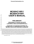
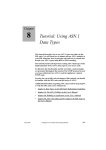
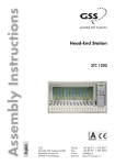
Remote Control Unit RCU 1 English for Standard and Profi Line Head-End Stations GSS Grundig SAT Systems GmbH Beuthener Strasse 43 D-90471 Nuremberg Phone: Fax: E-mail: Internet: +49 (0) 911 / 703 8877 +49 (0) 911 / 703 9210 [email protected] http://www.gss.de Contents 1 Safety regulations............................................................................................... 3 2 General information........................................................................................... 3 2.1 Packing contents.................................................................................... 3 2.2 Meaning of the symbols used.................................................................. 3 2.3 Technical data....................................................................................... 4 2.4 Description........................................................................................... 5 2.5 PC / laptop system requirements............................................................. 6 2.6 Overview of the management unit........................................................... 6 3 Installation......................................................................................................... 7 3.1 Mounting and connecting the management system..................................... 7 3.2 Assembling a connection cable............................................................... 8 3.3 Connecting further components............................................................... 8 3.4 EMC regulations.................................................................................... 8 4 Installing the software on a PC or laptop............................................................. 9 4.1 Key code (activation code) for the software............................................... 9 4.2 Installing the software............................................................................. 9 5 Connecting to a network................................................................................... 12 LAN configuration............................................................................... 12 Configuration via remote control software..................................... 12 Configuration via browser........................................................... 15 Check the configuration at the control unit of the head-end station.... 17 6 Software version of the management system..................................................... 18 7 Software update (firmware).............................................................................. 19 8 Reset................................................................................................................ 21 9 Factory Defaults............................................................................................... 21 10Remote access via Internet................................................................................ 24 11Software update of cassettes via the BE-Flash software...................................... 26 12Alarm messages by SNMP traps....................................................................... 28 12Final procedures............................................................................................... 30 - 2 - RCU 1 1 Safety regulations • Assembly, installation and servicing should be carried out by authorised electricians. • Observe the safety regulations and notes in the assembly instructions for the cassettes and head-end station used as well as the relevant safety instructions e.g the standards IEC/EN/DIN EN 50083 and IEC/EN/DIN EN 60728. Take action to prevent static discharge when working on the device! 2 General information 2.1 Packing contents 1 1 1 2 1 2.2 Meaning of the symbols used RCU 1 network cable 2 m RS-232 cable (9-pin Sub D) RS-232 plug (9-pin Sub D) ribbon cable (9-pin ca. 3 m) Important note —> General note • Performing works - 3 - RCU 1 2.3 Technical data The devices meet the following EU directives: 2006/95/EC, 2004/108/EC The product fulfils the guidelines and standards for CE labelling. Connections LAN.................................................................................. 1 RJ-45 socket RS-232:.................................................................... 2 Sub D 9-pin socket Socket 1.............. for connecting the head-end station (incl. power supply) Socket 2.......................................for connecting a 2nd head-end station or a monitoring cassette PSCU 6000/HSCU 6000 or a backup system PRS 16/8 SNMP (Simple Network Management Protocol - version 1): Alarm messages from the monitoring cassette PSCU 6000 / HSCU 6000 can be sent by SNMP trap. Monitoring cassette PSCU 6000 / HSCU 6000 The following items are signalled: – Level of the output signal measured via PSCU 6000 / HSCU 6000 – BIT – error rate at QAM output signals – Present line synchronizing signal at analogous PAL output signals – Present RDS station name at FM output signals – Quality of the input signal (good, poor and no signal) at QPSK-PAL double transmodulators as well as QPSK- QAM transmodulators Remote control and remote software updates: – Remote control is possible at all current cassettes and head-end stations of the Standard- and Profi Line. – To find out which cassettes can be updated via remote control see the product information on "www.gss.de". – Software updates are done via the BEflash software. Required index levels for remote control and remote updates: PSW 1000 index level: ≥ V37 BeFlash index level: ≥ V42 BE-Remote index level: ≥ V43 - 4 - RCU 1 2.4 Description Hardware concept: RCU 1 Router PC Internet Rosa System HSCU/PSCU 6000 PRS 16/8 The RCU 1 management system is equipped with a Server which can be connected to a PC or a LAN network via the LAN interface. A connection to the internet (and thereby remote control) is possible via a router. The basic units can be configured and remote controlled with software PSW 1000, a remote controlled software update of the cassettes can be done with software BE-Flash. The RCU 1 has two RS-232 interfaces (Sub D connectors): – Via interface 1 the RCU 1 will be connected to the control unit of the headend station to be remote. Also the power supply is done by this connection. – Via interface 2 a second head-end station, the monitoring cassette PSCU 6000/HSCU 6000 or the backup system PRS 16/8 can be controlled. Error messages from the PSCU 6000/HSCU 6000 monitoring cassette can be forwarded by e-mail or SNMP trap. A connected backup system PRS 16/8 can be configured by the software PSW 1000 via the RCU 1. - 5 - RCU 1 2.5 PC / laptop system requirements System requirements for the PSW 1000 software: – PC or laptop with a Pentium processor, – Windows 95*/98*/ME/2000/Vista/7 (*from Internet Explorer 5 on), – At least 32 MB RAM, at least 50 MB free space on hard drive, – LAN interface (RJ 45 socket) – Serial interface (RS-232 D-SUB socket) For PCs / laptops with a USB connection (without a serial interface), please use a standard USB / RS-232 adapter. – Internet access for downloads and remote maintenance. 2.6 Overview of the management unit 1 3 2 4 5 6 7 1 RS-232 interface 1 - connector for the head-end station (including the power supply) 2 3 POWER ON-LED RS-232 interface 2 - connector for a 2nd head-end station, a PSCU 6000/ HSCU 6000 or a PRS 16/8 4 5 6 7 Reset button (software reset) MAC address LAN socket Hole for the mounting screw - 6 - RCU 1 3 Installation 3.1 Mounting and connecting the management system The RCU 1 will be mounted below the control unit instead of the mask at the power supply unit. • Remove the front cover of the head-end station. • Disconnect the mains cable at the power supply unit. • Unscrew 2 screws 7, 8 (Fig. A). • Remove the power supply unit from the head-end station. • Disengage 2 latches 9 and remove the cover (Fig. E). • Reassemble the power supply unit and fasten it with screw 8. • Mount the RCU 1 in the oblong hole and fasten it with screw 7 (Fig. B). • Connect the RS-232 socket 1 of the RCU 1 via the supported RS-232 cable to the RS-232 socket of the control unit (Fig. C). • Connect the mains cable to the power supply unit and switch on the headend station. —> The display is switched off during synchronisation (about 30 seconds, Fig C). —> Fig. A —> Fig. B —> Fig. C Fig. Fig. - 7 - D E RCU 1 3.2 Assembling a connection cable External components are connected to the management unit with 1:1 RS-232 cables. You can assemble these cable in the required lengths by using the supplied RS-232 plugs and the ribbon cable. 9 9 5 5 1 6 1:1 RS-232 cable plug 1 6 socket • Cut off a section of cable to the required length. • Insert the ends of the cable into the openings on the RS-232 plug and RS-232 socket, making sure they are pushed in all the way. • Firmly close the sliders on the blade contacts. 3.3 Connecting further components • If necessary connect a 2nd head-end station, the monitoring cassette PSCU 6000/HSCU 6000 or the backup system PRS 16/8 to the RS-232 socket 2 by using a self-made 1:1 RS-232 cable. A combination with HRCU 8/PRCU 8 is not possible! 3.4 EMC regulations To comply with the current EMC regulations, it is necessary to connect the lines leading in and out of the head-end station using cable terminals. - 8 - RCU 1 4 Installing the software on a PC or laptop The PSW 1000 and BE-Flash software are not included in the scope of delivery of the RCU 1. The most current version can be downloaded from “www.gss.de”. If you do not have internet access, we will send you a DVD on request. 4.1 Key code (activation code) for the software A key code is required for the activation of the PSW 1000 software. This can be obtained from your regional authorised distributor. 4.2 Installing the software The PSW 1000 software can be downloaded from “www.gss.de”. If you do not have internet access, we will send you a DVD on request. • Unzip the "PSW1000_Vxx.zip" file and start the “setup_PSW1000_Vxx.exe” programme by a double click. • Select the desired language “German”, “English”, "Español" or “Français” and click the OK button to confirm. • When the “Setup-PSW1000” menu appears, click the “Next >” button. - 9 - RCU 1 • Read the license agreement. • Select “I accept the agreement” and click the “Next >” button. • A table will appear which lists the software versions of the cassettes which are compatible with the PSW 1000 software. Caution: After installing the PSW 1000 software, update the software for the cassettes if necessary. • Click the “Next >” button. • Specify the directory in which the PSW 1000 should be installed (e.g. C:\Programs\GSS\PSW1000). • Click the “Next >” button. • Enter a name for the shortcut to the program which will be created in the start menu. - 10 - RCU 1 • Click the “Next >” button. • Click on “Install” in order to proceed with the installation of the program, or on “Back” to make corrections or changes. A key code is required for the activation of the PSW 1000 software. This can be obtained from your regional authorised distributor. Click the "OK" button when entered the 25 key code. - 11 - RCU 1 5 Connecting to a network LAN configuration The "static" (fixed) IP address 192.168.0.120 and Port 60002 is set to the RCU 1. If another IP address range is used in your network or this IP address is already in use, first the IP address of the RCU 1 must be changed. If several RCU 1 are used in the network, different IP addresses and port numbers must be assigned for the RCUs: • Set a static IP address to your PC which is in the address range of the RCU 1 (e.g. 192.168.0.2, Subnetmask 255.255.255.0). • Connect your PC directly to the RCU 1 via a LAN cable. Configuration via remote control software Configuration via PSW 1000: • Start the PSW 1000 software. —> The installation of the PSW 1000 software is described in chapter 4 (page 9). • Click the button. —> The "Connection settings" window is activated. • In the menu "Connection settings" in area "Choice" select "Ethernet". • Enter the IP address and separated by a colon the port of the RCU 1: 192.168.0.120:60002 • Click the "OK" button. • If a password was set before enter the password. • Click the "OK" button. - 12 - RCU 1 —> The status indicator left below will change from . • Click the • Select which data should be imported. to button —> At least select "RCU 1". We recommend to import the complete data of the plant. • Click the "OK" button. —> The selected data will be imported. • Click the button. —> The "Plant settings" window is activated. • Select the Ethernet settings using tab - 13 - . RCU 1 • Enter the settings necessary for your network. Use only ports in the range of 35000 – 60100 or 61000 – 65000! Note the settings! • Click the • Enter the password (the standard is "GSS"). button - 14 - RCU 1 —> The head-end station reboots (ca. 1 minute). —> Now the RCU 1 is configured for your LAN network. • Disconnect the LAN connection to your PC. • Connect the RCU 1 to your network. Configuration via browser Configuration via browser: • Start any internet browser. • Enter the IP address of the RCU 1 (http://192.168.0.120) at the address line of the browser and press the "Enter" button: —> The "Login" window is activated. • Enter the user name ("RCU1" is the standard value) and the password ("GSS" is the standard value) and click the "OK" button. - 15 - RCU 1 • Click the "Setup" button. • Enter the settings necessary for your network. Use only ports in the range of 35000 – 60100 or 61000 – 65000! Change the password if necessary and store it with button "Save". Note the settings! • Click the "Save & Reboot" button. —> The changed settings are transmitted to the RCU 1. RCU 1 reboots. —> Now the RCU 1 is configured for your LAN network. • Disconnect the LAN connection to your PC. • Connect the RCU 1 to your network. - 16 - RCU 1 Check the configuration at the control unit of the head-end station Check the configuration at the control unit of the head-end station: • Activate the "System information" software by simultaneously holding down the buttons and for more than 2 seconds in the "Selecting the cassette" mode. —> The display darkens. Afterwards the "System information – control unit" – "SYSTEM INFO: BE_Remote" menu appears. —> The "System information" software also can be called up from the standby mode of the display. SYSTEM BE-Remote INFO: V 42 • Press the button so many times until the network configuration is shown in the display of the RCU 1. RCU-1 IP-ADDR 192.168.000.120 • Press the button. RCU-1 IP-MASK 255.255.255.000 • Press the button. RCU-1 IP-GATEWAY 192.168.000.001 • Press the button. RCU-1 IP-PORT 60002 - 17 - RCU 1 6 Software version of the management system The software version of the RCU 1 is shown in the "Detail of choise" menu of the management system when the plant settings are imported. - 18 - RCU 1 7 Software update (firmware) The software update of the RCU 1 is to perform by a TFTP server programme (e.g. "Tftpd32"). This programme is included in the ZIP file of the RCU 1 software. You will find the current software version for the RCU 1 at “www.gss.de”. If you do not have internet access, we will send you a DVD on request. If the LAN configuration is unknown, detect it, like described in chapter 5 "Check the configuration at the control unit of the head-end station". • Connect a PC like described in chapter 5 "LAN configuration" directly to the RCU 1. • Start the TFTP server programme "Tftpd32.exe" at this PC. • Select the " " menu. • Perform the following settings: - Host: IP address of the RCU 1 (e.g. 192.168.0.120) —> For a remote controlled update the external (public) IP address of the router connected to the RCU 1 must be entered. - Port: 69 —> For a remote controlled update port forwarding for TFTP port 69 (UDP protocol) must be configured at the router connected to the RCU 1. - 19 - RCU 1 - Local File: Enter the path of the file of the new software version using button " " (e.g. C:\rcu1_1.bin). - Remote File: /var/firmware.img - Block Size: e.g. 1024 (size of the data blocks to be transmitted). • Start the update with button " " —> The transferred blocks and the progress is shown. —> A message like this one is shown after a successful update: - 20 - RCU 1 8 Reset If RCU 1 "hang up", it can be reset by the reset button. —> Using a remote controlled IP power strip you can perform a remote controlled reset of the entire plant. 9 Factory Defaults By the following procedure you can reset the passwords, the LAN configuration or the complete RCU 1 to factory defaults. If the LAN configuration is unknown, detect it, like described in chapter 5 "Check the configuration at the control unit of the head-end station". • Connect a PC like described in chapter 5 "LAN configuration" directly to the RCU 1. • Start the Command Prompt (Start -> All Programs -> Accessories -> Command Prompt) at the PC. —> DISPLAY e.g.: C:\>_ • Enter the following sequence: telnet 192.168.0.120 —> Instead of "192.168.0.120" enter the IP address of the RCU 1. If an error message occur "telnet" must be activated in the operating system. • Press the "ENTER" button. —> DISPLAY: Connecting to 192.168.0.120… —> Display is cleared – new DISPLAY: uClinux login: _ • Enter the following sequence: root • Press the "ENTER" button. - 21 - RCU 1 —> DISPLAY: Welcome to For further information check: http://www.uclinux.org/ /mnt/flash/root # _ Reset the passwords: • Enter the following sequence: manudef password • Press the "ENTER" button. —> DISPLAY: Factory password settings restored. Settings overview: ========================================= LAN-Password: GSS Configuration-Password: has been removed ========================================= >>> System is rebooting in 3 seconds. —> The Ethernet (LAN) password is reset to "GSS", the configuration password has been removed, the connection is closed, RCU 1 re��� boots. Reset the LAN configuration: • Instead of "manudef password" enter the following sequence: manudef network • Press the "ENTER" button. - 22 - RCU 1 —> DISPLAY: Factory network settings restored. Settings overview: ========================================= IP: 192.168.0.120 Gateway: 192.168.0.1 Netmask: 255.255.255.0 TCP-Port: 60002 HTML-Port: 80 ========================================= >>> System is rebooting in 3 seconds. —> The LAN configuration is reset to the values shown above, the connection is closed, RCU 1 reboots. Reset to factory defaults: • Instead of "manudef password" enter the following sequence: manudef factory • Press the "ENTER" button. —> DISPLAY: Factory configuration restored. Settings overview: ========================================= IP: 192.168.0.120 Gateway: 192.168.0.1 Netmask: 255.255.255.0 TCP-Port: 60002 HTML-Port: 80 LAN-Password: GSS Configuration-Password: has been removed ========================================= >>> System is rebooting in 3 seconds. —> The RCU 1 is reset to factory defaults, the connection is closed, RCU 1 reboots. - 23 - RCU 1 10 Remote access via Internet To get remote access via internet the router connected to the RCU 1 must be connected to the internet. In addition the "public" IP address with which the router is connected to the internet must be known. —> Therefore you either need a "fixed", "static" public IP address, or you need to check the public IP address of the router before every remote maintenance via respective providers of dynamic DNS services (e.g. DynDNS.com). For remote maintenance via internet "Port Forwarding" must be configured at the router. —> Pay attention for the operating instruction of the router. —> If several RCU 1 are used, for each port used "Port Forwarding" must be configured. —> To get remote access via internet you need a PC with internet access • Start the PSW 1000 software. —> The installation of the PSW 1000 software is described in chapter 4 (page 9). • Click the button. —> The "Connection settings" window is activated. • In the menu "Connection settings" in area "Choice" select "Ethernet". • Enter the public IP address and separated by a colon the port of the RCU 1: 212.20.172.000:60002 • Click the "OK" button. - 24 - RCU 1 • If a password was set before enter the password. • Click the "OK" button. —> The status indicator left below will change from . • Click the • Select which data should be imported. to button —> We recommend to import the complete data. • Click the "OK" button. —> The selected data will be imported. —> The operation of the software PSW 1000 is described in the help file which is included in the software. - 25 - RCU 1 11 Software update of cassettes via the BE-Flash software —> The RCU 1 management system must already be configured. • Start the “BEflash.exe” programme (download from "www.gss.de"). • Set field "Serial Port:" in area "Configuration" to "Ethernet". • Select in field "Device:" in area "Configuration" the type of cassette which shall be updated. • Open menu "File"/"Open …" and select the corresponding data file (current software you will find at "www.gss.de"). —> At current cassettes and current software versions the type of cassette is selected automatically, the selection field "Device" is hidden. • At older cassettes select the type of cassette which shall be updated in field "Device:" in area "Configuration". - 26 - RCU 1 • After pressing the button or selecting the menu "Action" / "Program" the window "Select IP-Address" appears. • Enter the IP address and the port separated by a colon. —> In the example the IP address 212.20.172.0 and port 60002 is used. —> IP address and port must be set to the same value as selected during the configuration of the RCU 1, respectively the public IP address of the router and the port which must be forwarded to the RCU 1. • Enter the password and click the "OK" button. —> The submenu "Select Box" shows the current software version of the cassette and the slot in which the cassette is fitted. In this menu the cassette to be updated can be selected. • Start the programming by clicking the "OK" button. —> At some cassettes the programming starts not until the transmission is finished. —> Round about 45 minutes can be needed for transmission and programming of one cassette. —> "Programming OK" is shown in a green status line when the programming is finished successfully. —> In case of an error, the error text is shown in a red status line. - 27 - RCU 1 12 Alarm messages by SNMP traps Alarm messages can be sent by SNMP (Simple Network Management Protocol – version 1). • Activate the submenu "Plant setting" by clicking the the menu "Edit"/"Plant setting". button or selecting —> A PSCU 6000 / HSCU 6000 for monitoring must be present in your plant and the check box "PSCU 6000 / HSCU 6000 available" must be activated. • Activate the submenu "Alarm SNMP-Traps". - 28 - RCU 1 —> Three IP addresses can be entered and activated by hooks. In case of an alarm message it will be sent to the activated IP addresses as a SNMP trap. Below see an example of the structure of an alarm message: Seq { Int =1; SNMP Version Str =public; Community String Inform { Int =6; RequestId Int =1; Error Int =0; ErrorIndex Seq { Seq { OID =1.3.6.1.4.1.29343.1.0.0.1 Str =Alarm report: 1 Channel in Nuremberg (Tel.: 212.20.172.90:60003) been cancelled } } } } - 29 - RCU 1 12 Final procedures After installing the head-end station, upgrading accessories or installing cassettes it is necessary to tighten all cable connections, cable terminals and cover screws in order to maintain compliance with current EMC regulations securely. • Mount the front cover (see assembly instructions of the head-end station). Änderungen vorbehalten. Technische Angaben ohne Gewähr. © by GSS GmbH 29042010