1
Page 5 of 5
CHARGING RECOVERY TANK: __________________________________________
NOTE: THIS PROCEDURE IS USED TO SETUP THE UNIT FOR CHARGING. RECOVERY TANK
SHOULD HAVE AT LEAST A 25” VACUUM. THIS PROCEDURE IS DONE WHEN
RECOVERY TANK IS ON THE SCALE
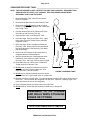
1. Be sure Recovery Tank valves (B) are closed.
Refer to FIGURE 4
2. Disconnect the Red hose from the Recovery Tank.
3. Disconnect and Re-Oil both the seals on Yellow
hose (C). Connect the long side of the Yellow Hose
to the Virgin Tank.
4. Connect the short side of the Yellow Hose to the
Red Valve on the Recovery Tank (B).
5. Open the Red Valve on the Recovery Tank.
6. Invert the Virgin Tank (A) and open valve. Open
Hand Valve (D) on the Yellow Hose to allow the
refrigerant to flow.
A
D
7. Raise the Virgin Tank to a higher level than the
Recovery Tank. Gravity and vacuum will transfer
the liquid refrigerant to the Recovery Tank faster
than reclaiming it.
C
8. Refer to the LCD Display to view the amount of
refrigerant that has been transferred.
9. After the desired amount of refrigerant has been
transferred, close valves on Virgin Tank and
Recovery Tank. Set Virgin Tank on ground upright.
B
10. Close Hand Valve on Yellow Hose. Disconnect
Yellow Hose from Recovery Tank.
11. Re-Oil seals on anti-blow back valve on the Red
Hose from unit and connect to Recovery Tank.
Open Recovery Tank valve (RED).
FIGURE 4 CHARGING TANK
12. Re-Oil seal on Yellow Hose and connect to service
port on back of unit. Open Hand Valve on Yellow Hose.
13. Plug the unit into a 115VAC outlet. Turn the compressor switch to ON, and the 3-way valve to
RECYCLE. This will reclaim the refrigerant from the hose. (Optional: Opening Virgin Tank
valve will recover the rest of the refrigerant.)
14. Once complete, disconnect Yellow Hose from Virgin Tank.
15. Re-Oil seals on Yellow Hose and connect to center port on Gauge Set.
REMEMBER TO OIL O-RINGS
AND SEALS WHEN ATTACHING
HOSES OR FITTINGS
INSTALLATION COMPLETE/SETUP COMPLETE
ZEEAC307A1 (03/26/1997) REV C.