1
IM2830-AXS4M.DOC
IM2830-AXS4
DIRECTORY: 962830A-X-S-4
Shadin Avionics
INSTALLATION MANUAL
FUEL/AIR DATA COMPUTER
P/N 962830A-1, 962830A-2, 962830A-3
Rev: M
2.8
Page: 2-14
Electrical Interface Specifications
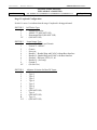
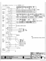
The specifications for the interfaces heading, fuel flow and baro are listed in this section.
2.8.1
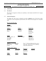
Heading Interface
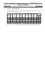
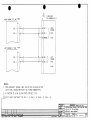
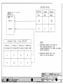
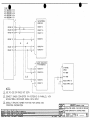
The heading interface follows the ARINC 407 standard (line voltage of 11.8 Vrms).
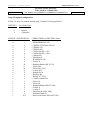
Synchro Leg
H
X
Y
2.8.2
Input Impedance
10 kohm
17 kohm
17 kohm
Fuel Flow Interfaces
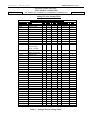
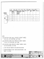
There are three basic types of fuel flow interfaces supported. The interface type is defined in the
ADC2000 part number. Refer to section 2.7 for the part numbering scheme.
2.8.2.1 Digital Fuel Flow Interface
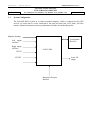
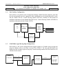
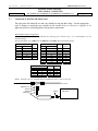
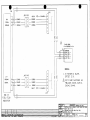
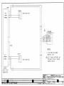
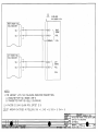
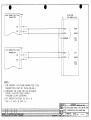
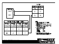
The are two possible installations for the digital fuel flow interface, the first is that the ADC is
connected to a dedicated fuel flow transmitter, and the second is that the ADC is connected into a
fuel flow system.
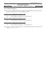
Dedicated Transmitter
Fuel Flow Interface Input Impedance
47 kohm
Shared Transmitter
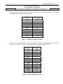
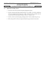
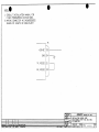
Under normal operating conditions the voltage swing (the signal amplitude) can be calculated
using Vs = [R/(R + 47 k)]*5 Vdc – 0.5Vdc, where R is the input impedance of the aircraft fuel
flow indicator.
For example with an input impedance R = 1 Mohm, the voltage swing Vs = 4.27 Vdc
With the fuel flow information is encoded in frequency and not amplitude, the loading effects do
not produce an error provided the aircraft indicator can detect the signal transitions.