1
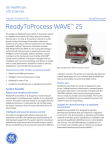
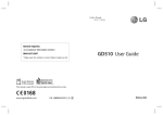
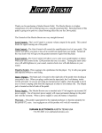
Automated Soil Compactor
S-333
Operator’s
Manual
Version 3.3
Durham Geo Slope Indicator
2175 West Park Court
Stone Mountain, GA 30087
USA
Phone: 800-837-0864 or
+1.770.465.7557
Fax: 770.465.7447
e-mail: [email protected]
www.DurhamGeo.com
TABLE OF CONTENTS
Safety Information
CHAPTER 3
3
CHAPTER 1
Set Up Instructions
Maintenance
13
Calibration
14
5
CHAPTER 4
Troubleshooting
CHAPTER 2
Operation
15
7
CHAPTER 7
Limited Warranty
16
RECORD THE FOLLOWING INFORMATION FOR FUTURE REFERENCE
Model / Type
S-333
Unit Serial Number
Date Purchased
Other
Before you operate this automatic soils Compactor:
Read all DANGER, WARNINGS, CAUTIONS AND INSTRUCTIONS included with
or attached to this Compactor. Follow all safety precautions to avoid personal injury
when operating this machine.
Durham Geo Slope Indicator cannot be responsible for damage or injury resulting
from unsafe product use, lack of maintenance, or incorrect product application.
Contact Durham Slope Indicator when in doubt as to safety precautions, design
criteria, or product usage.
All information, illustrations and specifications in this manual are based on the latest
information available at the time of publication. We reserve the right to make
changes at any time without notice and without incurring any obligation.
2
O P E R A T I O N
SAFETY INFORMATION
1.0
Safety Alert Words
Danger
Indicates an imminently hazardous situation which, if not avoided, will
result in death or serious injury.
Warning
Indicates a potentially hazardous situation which, if not avoided, could
result in death or serious injury.
Caution
Indicates a potentially hazardous situation which, if not avoided, may
result in minor or moderate injury. It may also be used to alert against
unsafe practices.
Important
Will alert you to the potential for damage to the product or loss of
data.
Note
Provide you with additional information to simplify a procedure or
clarify a process.
2.0
Specific Safety Information
WARNING:
High voltage and rotating parts can cause serious or fatal injury. Safe
installation, operation, and maintenance must be performed by qualified
personnel. Familiarization with and adherence to NEMA MG2, the National
Electric Code, OSHA and local codes is recommended.
It is important to observe the following safety precautions to protect personnel from
possible harm.
2.1
Be familiar with the Compactor and read all instructions thoroughly before
installing or working with it.
2.2
Be careful, and follow the prescribed procedures when handling and lifting
the Compactor, as it is top heavy.
2.3
Do not install this Compactor in an explosive atmosphere.
2.4
Avoid contact with energized circuits or rotating parts.
3
O P E R A T I O N
2.5
Follow all applicable local electrical and safety codes as well as the
National Electric Code (NEC) and the Occupational Safety and Health Act
(OSHA) in the United States.
2.6
Do not depend on motor control devices (motor starters, etc.) to prevent
unexpected motor starting. Always disconnect power sources before
working on or near a motor or its connected load.
2.7
Avoid touching capacitors until safe discharge procedures have been
completed.
2.8
Be careful about touching an operating motor; it may be hot enough to hurt
or injure you. Modern motors are designed to run hot under full load.
2.9
Protect the power cable. Don't let it touch sharp objects, hot surfaces, oil,
grease, or chemicals. Do not kink the power cable.
2.10
Make certain that the power source conforms to the requirements of your
equipment.
2.11
When cleaning electrical or electronic components, always use an
approved non-flammable cleaning agent such as a dry cleaning solution.
Be careful about choosing and using cleaning agents. Some of them attack
motor insulation, finish, or bearing lubricant; some are highly flammable. If
using cleaning agents, make sure the area is well ventilated.
2.12
Avoid prolonged exposure to high noise levels from this Compactor.
2.13
To prevent accidents, be sure to guard this Compactor against access by
children or other unauthorized personnel.
2.14
Wear safety glasses to protect your eyes when running this Compactor.
2.15
Keep all body parts away from hammer while running Compactor.
4
S E T - U P
I N S T R U C T I O N S
1
Chapter
SET-UP INSTRUCTIONS
CAUTION
The COMPACTOR plus pallet weighs approximately 230 lb (105 kg). The unit is top-heavy.
WARNING:
When the Compactor is shipped, the hammer should be in the down position. If the
hammer head is not down and it is in full view, do not make any adjustments until after you
have reviewed ALL operating instructions and procedures contained in this manual
including the section, "Dropping the Hammer". If the hammer falls unexpectedly, it could
easily cut off a finger or severely damage a hand.
IMPORTANT— Make certain the power source conforms to the requirements of this
Compactor.
3.0
Unpacking:
The COMPACTOR is top heavy, therefore handle it with care to avoid dropping it.
Before unpacking the COMPACTOR, inspect it to make sure it was not damaged in
shipment. If it is damaged, contact the carrier immediately. Remove the holding strap
on the hammer. Remove the three bolts which fasten the COMPACTOR base to the
pallet.
4.0
Power Requirements
CAUTION
Make sure the electrical power is disconnected before attempting to inspect or change the
fuse.
4.1
The AC power requirements of your COMPACTOR are clearly marked on the
label. The internal fuse is located on the motor mount. This fuse is an 8 A, slow
blow, 1/4" x 1-1/4", 250 V.
4.2
There are 2 power connections for the unit: a standard 110 V plug for the motor
supply and a 9 V transformer supplying power to the circuit board. Both of these
5
S E T - U P
I N S T R U C T I O N S
must be plugged in for the unit to work.
5.0
5.1
Support Base Requirements
Set-Up Instructions:
The energy from the hammer striking the sample in the mold must be supported
on a level, non-yielding surface which is equal to a 200 lb (91 kg) block of
concrete. The COMPACTOR must be bolted to this surface for stability. A quick
drying leveling cement such as Pour Stone or Rockite can be poured on a nonlevel concrete base to facilitate a level, stable surface. Either of these products
can be prepared in a liquid state just before placement of the COMPACTOR.
5.2
Optional Raised Pedestal:
A concrete pedestal may be poured to raise the COMPACTOR height if the base
for the pedestal is equal to the 200 lb (91 kg) block of concrete. To determine
the height of the pedestal, take your ceiling height and subtract one of the
following examples below for the molds which you intend to use. The examples
below are based on the COMPACTOR height of 54.4 " (1382 mm) and the
maximum drop height of 18" (457mm) taken from the top of the maximum sample
height.
For ASTM or AASHTO molds, use 80 inches (2032 mm)
For CBR molds, use 83 inches (2108 mm)
6
O P E R A T I O N
2
Chapter
OPERATION
WARNING:
When the COMPACTOR is shipped, the hammer should be in the down position resting on
the rubber pad it was shipped on. If the hammer head is not down and it is in full view, do
not make any adjustments until after you have reviewed ALL operating instructions and
procedures contained in this manual including the section, "Dropping the Hammer". If the
hammer falls unexpectedly, it could easily cut off a finger or severely damage a hand.
6.0
Control and display panel
Blow counter. Counts the number of hammer blows for the current layer and
automatically resets the counter to zero at the end of the preset counts. Counts up
999 blows maximum.
Preset Counter Wheel:
Indicates the desired
number of hammer
blows or cycles per layer.
Lift counter. Counts one lift
at the completion of the cycle
counter preset. This digit
may be reset with the reset
button. Will continue to add
lifts until it is reset.
Three buttons to set
each digit (of the number
of blows)
Run light is ON when the
machine is running
Manual jog button.
Momentarily moves the
hammer to the desired
position. Hammer moves
as long as the button is
depressed.
Lid Open or
Emergency
Stop Button
Pushed
Emergency Stop Button
(not shown). This button will
stop the machine
immediately. After this
button has been pushed, the
button locks down. To
release the button, turn the
button clockwise
Reset button (white). Pressing the RESET button once
will reset the “BLOWS” display to zero. Pressing the
button a second time will reset “LIFTS” and “BLOWS”
to zero. Pressing the button a third time rests the
complete display.
Start button. If pushed
again, it will interrupt
the run mode but does
not reset counter.
7
S P E C I F I C A T I O N S
NOTE:
Under normal use, the hammer
will always stop in safe park
position (3/4 lift position).
7.0
Dropping the Hammer (Procedure A)
If you must adjust the hammer to a position other than up (park position), use the
following procedure.
IMPORTANT — Place soft piece of wood over the mold platen or the rubber plate
that was supplied during shipping.
CAUTION
Keep hands away from compaction area.
7.1
Press emergency stop button.
7.2
Press reset button (white).
7.3
Register two counts in counter.
7.4
Press and hold jog button (do not release).
7.5
Release emergency stop button (twist to unlock).
7.6
Still holding in jog button, press start button.
7.7
Momentarily release jog button and hammer will move. Continue this action
to place hammer in desired position and then press the emergency stop
button.
7.8
Press in emergency stop button.
7.9
Press reset button.
7.10
To place hammer in park position: Use "Procedure C".
NOTE:
Hammer in lowest position can be lifted by hand. NO Latching will take place.
When hammer is partially lifted, it is possible to push hammer up and Latch.
8
O P E R A T I O N
CAUTION
It is dangerous to use the jog button to place hammer at top end of lift.
8.0
Starting the Compaction Hammer (Procedure B)
8.1
Place and clamp 4 in or 6 in mold onto base plate. Be careful to centralize
mold on locating pin.
8.2
Using "Procedure A" but with soft wood block resting on top mold, allow
hammer to drop.
8.3
With hammer in dropped position, check clearance of 2 in (51mm) dia. head
or pie head with side of mold. Adjust lower plate to give clearance of 0.100
in (2.54 mm) head to inside of mold.
8.4
Use "Procedure A" to lift hammer away from mold or allow hammer to
automatically park by setting one blow in counter and press start.Then
press emergency stop button.
8.5
Set counter to required blows.
8.6
Press reset button.
8.7
Release emergency stop button (twist).
8.8
Press start. Machine will strike sample the amount of blows in counter. The
display will count up when counts are completed. The lift section of LCD will
register one.
8.9
Repeat process until required lifts are completed as required by the relevant
standard.
9.0
Parking the Hammer ( Procedure C)
To place the hammer in the park position:
9.1
set the counter to 001.
9.2
With a piece of soft wood over the platen, push the start/stop button. The
COMPACTOR should cycle one time and park the hammer.
10.0
Clamping the Mold Platen:
CAUTION
Make sure the electrical power is disconnected before attempting to adjust the mold
platen.
9
O P E R A T I O N
10.1
Lift the hammer up to a position just above the height of the mold.
Adjustment
for toggle
clamps
Option #1
Install the 4" or 6" mold to the
platen using the toggle
clamps provided. See the
image on the next page. The
mold platen slides to the right
and left. There is a cam nut
that can be twisted for a stop
for repeated quick centering
of the molds. There are two
nuts located under the mold
platen which adjust the toggle
clamps for a secure,snug fit
to the mold base.
Option #2
Simply bolt a 4” or 6”
Durham Geo Slope Indicator
mold base to the compactor
base with ¼-20 bolts.
Leave this attached with the
threaded rods and wing nuts.
Then when the test is complete,
remove mold and leave base
attached
10
O P E R A T I O N
11.0
Adjusting the Hammer Drop Height:
Hammer drop heighs may be either 12 inches (304.8 mm) or 18 inches (457.2 mm).
11.1
To adjust the hammer drop height to 12 inches (304.8 mm), open the lower
front panel door and place the two 1-1/4 inch (32 mm) round aluminum bars
on the two pins (item 10) under the hammer pickup bar.
11.2
To adjust the hammer drop height to 18 inches (457.2 mm), open the lower
front panel door and remove the two 1-1/4 inch (32 mm) round aluminum
bars on the two pins under the hammer pickup bar.
12"
18"
11
O P E R A T I O N
12.0
Changing Hammer Weights:
12.1
WITH E STOP PRESSED Use a
wrench, locate the hex nut on
top of the lift bar.
12.2
Turn counter-clockwise to
loosen.
12.3
Continue turning by hand until
rod can be pulled out of lift bar,
but do not need to remove lift
bar.
12.4
Remove the weight by
grasping hold, and rocking
back and forth and pull the
weight down
12.5
The Weight should remove
straight down or with a gentle
blow with a soft hammer strike
downward on weight till
removed.
12.6
With the new weight, grab hold
of the lifting bar and slide the
weight over the lift bar until if
stops.
12.7
Twist the weight when the bar is
fully seated to make sure the
alignment pin is located
correctly. This will prevent the
weight from twisting during the
operation.
12.8
With wrench at the top hex turn
clockwise until tight.
12
O P E R A T I O N
DO NOT OVERTIGHTEN.
13
O P E R A T I O N
3
Chapter
MAINTENANCE AND
CALIBRATION
Your COMPACTOR is a precision machine designed to give you years of troublefree service. A minimum of care is necessary and taking the precautions listed
below will extend the life of your machine.
NOTE: There is a grease fitting located on the bottom side of the rotary platen
Please grease weekly. With Weight lifted on the platen, pump grease while rotating
platen by hand. Platen will only rotate clockwise
Keep loose soil removed from around platen area daily
NOTE: All bearings are grease packed and sealed. However, check all bearings
occasionally for wear.
NOTE: We recommend the following parts be kept on hand.
2- P/N 4148-01 Vee Bushing
1- P/N 4147-01 Pinch Plate
NOTE: At all times keep dust and water away from moving parts. A clean machine
will give you years of trouble-free duty.
1.0
Gear case Lubrication:
1.1
During the Break-in Period: Change the gear case oil after the first thirty
hours of operation, using the AGMA recommended worm gear lubricant #
8EP.
1.2
Regular Maintenance: Maintain the correct amount of oil in the gear case
to lengthen the gear/motor operating life.
After the first week of gear motor operation and twice yearly after that,
completely drain the gear case oil and then refill the gear case with new oil.
Fill the gear case up to the horizontal centerline plug. Some bronze flakes
14
O P E R A T I O N
will be present in the drain oil, especially at the first oil change because of
the normal worm gear wear-in process.
2.0
Calibration
2.1
We recommend calibrating the unit annually. Use Durham Geo Slope
Indicator calibration kit #S-33020 for calibration in accordance with the
ASTM D 2168 or other accepted calibration procedures.
2.2
To adjust the 18" (457.2 mm) drop height, open the front panel door and
locate the two black dampers in the lift bar. These dampers have locking
nuts on top of the lift bar. Loosen the nuts and turn the damper body
counter-clockwise to increase the lift height. As you turn the two dampers
equally, the lift bar will lower, and this will increase the drop height.
If you need to decrease the drop height, reverse the procedure.
IMPORTANT — Motor damage may result if the above instructions are not
followed.
15
6
Chapter
T R O U B L E S H O O T I N G
TROUBLESHOOTING
This chart is to aid the user in troubleshooting problems that may occur. If
problems persist or need assistance, please contact us.
Factory Phone: 1-800-837-0864
__________________________________________________________________
No Power to Panel
Plug in 9 volt Power Supply
Motor does not Start
Plug in 110v Power cord
Machine does not start
After programming blows
“LO light lit on door
Pull E-Stop out or
Close Panel Door
__________________________________________________________________
Bottom Platen Does not Rotate
Cable Broken
when machine is operating
Grease platen weekly
And daily clean out around
Platen area to prevent strain
On cable
__________________________________________________________________
Unit working but not counting
Prox switch loose
Call Factory
on Operator panel
16
L I M I T E D
7
Chapter
W A R R A N T Y
LIMITED WARRANTY
The S-333 Soil Compactor is guaranteed against defective materials and workmanship
for a period of one year from the date of shipment. We will repair or replace such items
as may prove defective at our option. Under no condition will we allow labor charges or
other expenses to repair defective merchandise without our approval. Durham Geo
makes no other warranties of any kind or nature and all implied warranties or
merchantability or fitness for a particular purpose which exceeds the previously stated
obligation are expressly excluded. We accept no responsibility for damage or abuse to
apparatus due to improper installation or operation. We accept no responsibility for and
will not pay for any lost profits incidental, consequential or special damages.
For a complete warranty disclosure, please
e-mail [email protected]
Call 1-800-837-0864 (outside Georgia, USA) or
(770) 465-7557 (inside Georgia, USA)
Refer to the printed statement on the back of any Durham Geo Slope Indicator
original invoice.
17