1
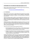
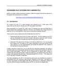
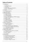
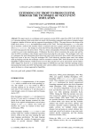
Ethernet XServer User’s Manual
CAT5 cable
9 to 24V DC
Power Supply
for PLC
RJ45 plug
Status LEDs
-
Ethernet Socket
+
To Ethernet Switch
or Router
To RS232 port of
PLC or Auto485
Figure 1 – Connecting Ethernet XServer.
1. Introduction
The Ethernet XServer provides a low cost and extremely simple way for the M-series
PLC to be connected to the TCP/IP network of the corporate LAN, WAN or the
Internet. The XServer can replace a PC running TLServer and provides reliable TCP/IP
network services to one or more M-series PLCs continuously. Naturally, the TRiLOGI
programming software and TRi-ExcelLink works instantaneously with the XServer,
allowing remote programming and process monitoring over the LAN or the
Internet. In addition, the XServer can also host multiple web pages and Java
applets so that users of the equipment can control/monitor the equipment using
their web browser from anywhere in the world.
2. Physical Mounting & Wiring
Measuring only 2.75” x 1.5”, the extremely compact XServer can be easily installed
in any tight corner within the same control panel that houses the PLCs. You need to
use 4 PCB standoffs to support the controller and fasten it to the base plate. (You
can also purchase the optional DIN Rail Adapter kit, Part #: DIN-KIT-EX, which can
greatly simplify installation to the DIN rail).
A. Power Supply
The Ethernet XServer requires a single 9 to 24V DC power source, which may be
shared with the same power supply to the PLC. Simply connect the power
Ethernet XServer User’s Manual
supply cable to the two-way screw terminals as shown in Figure 1. Check to
ensure that the polarity is correct before turning ON power to the PLC. Note that
the XServer consumes only about 50mA current @ 24V DC.
B. Connection to the TCP/IP Network
The XServer has a single 10/100Mbps Fast Ethernet port & RJ45 socket, which
can be connected readily to a network hub, switch or router using a standard
CAT5 cable with RJ45 plug, as shown in Figure 1. Note that although RJ45 is a
standard Ethernet connector widely used in office LAN connection, it is not
designed to withstand very abusive industrial environment. Hence care should
be taken to house the XServer inside a protective control panel that minimizes
exposure to dust, heat, moisture or chemical fumes.
C. Connection to the Wireless LAN (802.11 or Wi-Fi)
If your premise already has a Wireless LAN in place, then you can connect the
XServer to your Wireless LAN easily by means of an inexpensive Wireless Ethernet
bridge, such as the WET11 made by Linksys. All you need to do is to first set up
the WET11 to integrate into your Wi-Fi network, and then just connect a CAT5
cable between the WET11 and the XServer Ethernet port and your XServer
(along with your PLCs) will instantly become a member of your Corporate LAN!
D. Connection to the M-series PLCs
The XServer has a male DB9 serial port, which can be connected directly to the
PLC’s RS232 port (COMM1 only) using a straight DB9 cable. You can also use an
Auto485* adapter to connect a single XServer to 31 standard M-series PLC via
RS485 (or up to 255 PLCs if the PLCs are fitted with 1/8 power RS485 driver, such
as the 75HVD3082). Since RS485 allows wiring distance of up to 4000 ft, you
may also use Auto485 so that you can install the XServer at a location closer to
the office LAN port that but located further away from the hostile factory floor
environment.
2
Ethernet XServer User’s Manual
*Note: Since the Server’s RS232 port does not control the RTS pin, you can only
use an “Auto-turnaround type” RS232 to RS485 converter for this
purpose, such as the Auto485 converter in “Auto” mode.
3. Configuring the XServer’s Ethernet and RS232 Ports
The XServer’s Ethernet Port has been pre-configured in the factory to look for a
DHCP server that will assign it a dynamic IP Address. However, in most field
installation a static IP address may be more desirable. You can configure the
Ethernet and the RS232 ports using the “XServer Setup” CD-ROM included in your
XServer Starter Kit.
First, run the “Setup.exe” program in the CD-ROM and follow the on-screen
instructions to install the “XServer Setup” program in your PC. Then click “Start>XServer Configuration Utility” and execute the “XServerConfig” program. You
should see the configuration screen as shown in Figure 2.
Figure 2
Next, find the configuration cable which has female DB9 connectors at both end
of the cable. Connect one end to the XServer and the other end to the PC’s COM
port. (Make sure that there is no other program such as the TLServer running on the
PC that uses the same COM port).
3
Ethernet XServer User’s Manual
You have to put the XServer in configuration mode before using the utility program
to change the configuration. You achieve it by turning ON DIP switch #1 before
applying power to the XServer. (Note: the red color “CFG” status LED will light up
when DIP Switch #1 is turned ON). If the XServer power is already on, you can also
reset it by pressing the “RESET” button on the board. Wait a few seconds until the
green status LED “RDY” is lit. The board will then be in configuration mode ready to
interact with the “XServerConfig” program.
You can now click the “Retrieve Parameters from XServer” button to retrieve the
previously stored parameters. If all goes well the program should report that the
parameters have been successfully retrieved from the XServer. If you encounter
any error, please check to ensure that serial cable is properly connected. If you
are connecting the XServer to a PC serial port that Is not COM1: you should click
on the “Serial Setup” button (See Figure 2) to select a different COM port before
attempting to retrieve the parameters.
Once the parameters have been retrieved, you can make changes on any of the
fields and the click on the “Save Parameters to XServer” button to update the
changes to the XServer. The explanations for each field are described below:
a. Obtain IP Address : Automatically (DHCP) or Manual
When “Automatically” is selected, the IP address will be set as “0.0.0.0” which
instructs the XServer to look for a DHCP Server when it is first powered ON to
obtain an assigned IP address. You have to define a suitable subnet mask that
fit your network requirement. On most small network router (such as those 4 or 8
ports router made by Linksys or Netgear) the subnet mask is usually defined to
be 255.255.255.0, which allows up to 256 devices to be connected to the
router. For larger network your System Administrator will be able to provide you
with the required subnet mask values.
For industrial applications, it is probably more suitable to have a static IP
address so that the device can be accessed with certainty. By clicking on the
“Manual” Option you can enter the static IP address in the “IP Address” fields.
You have to ensure that the IP address you use is unique and not already been
assigned to another device on your network. The static IP address should also
be outside the scope of addresses of the DHCP server. Please ask your system
administrator to assign you a valid static IP address for your XServer so that the
System Administrator can keep track of a list of IP addresses that have been
assigned.
AutoIP
If the XServer cannot find a DHCP server, and you have not manually assigned
an IP address to it, XServer will automatically select an address from the AutoIP
reserved range (which is from 169.254.0.1 to 169.254.255.1) .The XServer sends
out a (ARP) request to other nodes on the same network to see whether the
4
Ethernet XServer User’s Manual
selected address is being used. If the selected address is not in use, then
XServer will use it for local subnet communication. If another device is using the
selected IP address, the unit selects another address from the AutoIP range and
reboots itself. After reboot, the unit sends out another ARP request to see if the
selected address is in use, and so on until it finds a suitable IP address.
AutoIP can be disabled by setting the XServer’s IP address to 0.0.1.0. This setting
enables DHCP but disables AutoIP.
b. GateWay IP Addr
The Gateway IP address lets XServer communicate to other LAN segments or to
the Internet. The gateway address is usually the local IP address of the router
where XServer is connected. For small local network with no plan for
connection to the Internet, the Gateway IP Address is not needed and can be
set to 0.0.0.0. But if you plan to use the XServer email capability then you mujst
fill in the correct Gateway IP Address. Ask your system administrator if you have
any questions.
c. SMTP Server IP Address
The SMTP (Simple Mail Transport Protocol) Server fields let you define the IP
address of the email server that the XServer can use to send out emails based
on email service requests it receives from the PLC. This is the same SMTP server
that your normal email client software such as the MS Outlook uses to send
email. You can ask your Internet Service Provider (ISP) for the IP address of their
SMTP server. The ISP usually provides the SMTP server in domain name form
(such as “mail.sbcglobal.net” but you should also be able to request for the
numerical IP address of the SMTP server from the ISP.
You can also use the Unix tool “dig” or “host” to resolve the domain name into
numerical IP address. For Windows users, you may be able to search the
Internet for a free “host.exe” tool that let you resolve the IP address from a given
domain name (one host.exe tool that we found to work was downloaded from
http://pigtail.net/LRP/dig/) . For example, executing the command line: “host
mail.sbcglobal.net” resolves into 4 IP addresses. Any one of them can be used
as SMTP IP address here (provided your ISP is SBC, almost no SMTP server will
relay emails from client that is not their own subscribers)
If you do not plan to use the XServer send out emails then you can leave the
default SMTP Server IP Address = 0.0.0.0.
d. DNS Server IP Address
DNS (Domain Name Server) allows the XServer to contact a remote location by
means of domain name instead of IP Address. The DNS takes in the given
domain name (such as yahoo.com) and returns the IP address of the target
server. If you use a DHCP router and obtain IP address automatically the router
5
Ethernet XServer User’s Manual
will usually provide the DNS info automatically. However, if you define your own
IP address then you need to fill in the DNS IP Address only if you are asking
XServer to contact a remote server by domain name instead of by IP Address.
However, currently this feature is not supported on XServer and hence it may be
left as the default value of 0.0.0.0.
e. XServer Port No.
The Port number is a 16-bit integer (range 0 to 65535) that needs to be
specified on top of the IP address when accessing the XServer from across the
network. The default value is 9080, which is the same default value used by the
TLServer and TRiLOGI client software. Please see the TRiLOGI programmer’s
manual for an explanation of the use of the port number. One reason why you
may want to change the port number is to use the “port forwarding” capability
of an NAT router so that different XServers may be accessible from the Internet
using the same public IP address of the router but with different port numbers.
f. Node Name
You can assign a name for this XServer using up to 8 ASCII characters. The
node name will appear on the router’s “DHCP Client table” for easy
identification of each node.
g. Username and Password.
You can use the username and password feature to prevent unauthorized
access to the XServer. It uses the same proprietary encryption scheme used in
the TLServer and TRiLOGI software to encrypt the password transmission.
However, unlike the TLServer that allows you to define unlimited number of
username and password, the XServer only permit a single username and
password and these are limited to a length of 8 characters each.
h. Use Username/Password (yes/No)?
In applications where there is no danger of unauthorized access to the XServer,
you can elect not to use the username/password. With the “No” option
selected, the TRiLOGI client or Java Applet can log-in to the XServer using
whatever username and password since XServer will bypass the username and
password authentication and allow the client to login.
i. Access Level
You can define the access level that the TRiLOGI client is permitted to operate
on the PLC. Three access levels are currently defined: 1 for Programmer, 2 for
User and 3 for Guest. . Please see Internet TRiLOGI Programmer’s Reference for
the definition of the access levels.
6
Ethernet XServer User’s Manual
j. XServer COM Port Baud Rate
The XServer’s RS232 COM port has to be set to the same baud rate as the
PLC(s) for successful communication. The default baud rate is 38400 bps,
which is the default baud rate of M-series PLCs. If you have defined the PLC
(using the SETBAUD command) to another baud rate, then you have to change
this setting to match the PLC’s baud rate. Note that XServer only supports a
single communication frame format of 8 data bit, 1 stop bit and no parity.
Please note that this COM port setting only takes effect when the XServer is
rebooted into “Operation” mode (i.e. reset with DIP Switch #1 in the OFF
position). The XServer only uses baud rate of 38400 bps during “Configuration”
mode regardless of the value of this setting.
4. Operating The Ethernet XServer
With the XServer connected to the Ethernet and the PLC and the DIP Switch #1 at
the “OFF” position, turn ON power to both the XServer and the PLC and wait till the
green “RDY” LED lights up. The XServer will now be ready in “Operation Mode”. Note
that it may take 5 to 20 seconds for the XServer to be ready which is much longer
than the PLC typical boot up time. Hence if you are programming the PLC to use
the “1st.Scan” pulse to initialize the XServer, your program will have to check for the
operational readiness of the XServer before issuing any command. You can let the
PLC send the “<IP>” command described later to check for the readiness of the
XServer.
If you have defined a static IP address for the XServer, then you can immediately
open up the Internet TRiLOGI 5.3 program. Select “Online monitoring” from the
“Controller” menu and enter the IP address and the port number. If all goes well,
the TRiLOGI program will be in communication with the PLC and you will see the Tx
and Rx LEDs blinking away, which indicate a continuous exchanges of command
sand responses between the TRiLOGI software and the PLC (via the XServer). You
can perform everything that TRiLOGI can normally do with TLServer except loading
or saving files to the XServer.
If you have configured the XServer to use DHCP server, then you will need to
determine the IP address that is assigned by the DHCP server before you can use
TRiLOGI program to communicate with it. Here is how:
a. Find out from the DHCP server: Most routers
employ browser interface that allows you to
open a “DHCP Client Table” to find out the list
of IP addresses that the DHCP router has
assigned to the devices connected to it. You
can check the IP address for an assigned
device that matches the “MAC address” of
7
Ethernet XServer User’s Manual
the XServer. The MAC address is a unique 48-bit number that each Ethernet
device must have. The MAC address on the XServer is of the format
“00:20:4A:XX:XX:XX”, which is printed on the body of the XServer’s Ethernet
connector port as shown in the picture.
b. Use the PLC to request the IP address from the XServer: If you connect the
XServer to a single PLC, you can program the PLC to send a special command
string “<IP>” to the XServer and the XServer will return its IP address to the PLC.
To make your job easier we have created a PC5 file that does just that – the
”GETIPADDR.PC5” program found on your XServer CD-ROM or from:
http://www.tri-plc.com/trilogi/xserver.zip
Unzip all the files in the above archive into your PC’s samples folder and transfer
the “GETIPADDR.PC5” to the PLC (use the serial cable and TLServer to do the
transfer if you don’t already know the XServer IP address). Click on the input #1
and the PLC will attempt to query the XServer for its IP address. It will display the
returned IP address on the LCD or display an error message if it is unable to get
any response from the XServer.
Once you have determined the IP address of the XServer, you should use the
“Ping” utility in your PC to test the IP address. For Windows, click “Start -> run”
and then enter “PING” followed by the IP address (do not include the port
number). E.g.
You should receive response such as “Reply from 192.168.1.123 time = xx ms
TTL = nn” which indicates that the XServer is alive and is responding to the Ping
request from your PC. You can now use the IP address: port in your Internet
TRiLOGI program to perform program transfer and online monitoring.
Important Note
The XServer supports up to a maximum of four simultaneous connections
from the clients. Once 4 connections have been established a new client
that attempts to login to the XServer will report a “Server not found” error. So
do remember to close any unused connection so that the XServer can be
available to other clients.
8
Ethernet XServer User’s Manual
5. Using the XServer Network Services (NS)
If you connect only a single PLC to the XServer via RS232, then the PLC will able
to send commands to the XServer to instruct it to perform a number of network
related functions (we shall use the abbreviation “Network Services”, or NS in short to
describe them). This is similar to the “File and Email Services” that the TLServer
provides to the PLCs, but there are some differences. Through the XServer, a PLC is
now able to connect remotely to another PLC in another part of the world via the
Internet! This allows peer-to-peer networking, or so-called “M2M” (machine to
machine communication) to take place between the PLCs.
Important Note
The NS Services require full-duplex connection between the XServer and the
PLC via RS232 port only. If you intend to use the NS services provided by
XServer, then do not use RS485 connection since the half-duplex RS485
network does not allow the PLC to use “STX” and “ACK” handshaking
scheme with the XServer when the XServer is in the midst of transmitting
commands to the PLC. The turnaround delay can also give problem during
arbitration between the PLC and XServer.
All NS commands begin with a string enclosed within the angle bracket called a
“tag”, e.g. “<EMAIL>”, “<CONNECT>”. Most NS commands end with a closing tag
“</>” except the “<REMOTE>” tag, which ends with a “</REMOTE>” closing tag.
Depending on the command type, the XServer may return one or more response
strings to the PLC, from which the PLC can read to determine if the command has
been executed properly.
The PLC can only interact with the XServer by means of TBASIC INCOMM,
OUTCOMM, INPUT$ and PRINT commands. It uses the PRINT and OUTCOMM to send
NS commands to the XServer and the INCOMM and INPUT$ to receive the data
from the XServer. However, this can present a problem because if the XServer is
busily passing data to and forth to the PLC in response to a client, then an untimely
NS command sent by the PLC can be mistakenly passed back to client program
and disrupt the on-going communication with the client. In addition, the PLC buffer
up to 256 bytes of serial data coming through its COMM port, which includes those
host link commands it received in previous communication session. Therefore, if
the PLC executes a simple “INPUT$” statement, all it receives will likely be an old
host link command string it got in the previous communication instead of the
expected response string that is a result of the NS command it sent.
In order to resolve this potential conflict, the XServer implements an arbitration
scheme which, when used properly, can allow the PLC to send NS commands
while in the midst of communicating with XServer as a slave. Here is how it works:
9
Ethernet XServer User’s Manual
1) The PLC should send a STX character (ASCII 2) to the XServer to signal to the
XServer that it wishes to send a NS command.
2) The XServer, upon receiving the STX character, will complete all current
communication exchanges with the PLC and put new communication
exchanges on hold temporarily. It will then send an ACK character (ASCII 6) to
the PLC to signal to the PLC that it is ready to accept the NS command.
3) After sending the STX character, the PLC should continue to read from its serial
input port one byte at a time until it receive an ACK character from the
XServer. At this point the PLC would have cleared its serial input buffer and,
having received the ACK character from the XServer, it can now proceed to
send the NS command to the XServer and use the INPUT$ command to read
the response correctly from the XServer.
4) After the XServer completed the NS service request sent by the PLC, it will
resume execution of suspended communication sessions with other clients.
Thus the client will not lose communication with the XServer for too long.
The “testxserver.pc5” program in the “XServer.zip” file (on your XServer Configuration
CD-ROM or from http://www.tri-plc.com/trilogi/xserver.zip) includes a few examples
of sending NS commands to the XServer. All examples call the custom function
“SENDNSREQ ” to perform the arbitration with the XServer before they proceed to
issue the NS commands. Please study the content of the examples to learn the
arbitration technique and the network services commands.
The following sections describe the various Network Service commands available
to the PLC.
a. Get IP Address
Format:
<IP>
Response:
xxx.xxx.xxx.xxx:nnnn (IP address:port of XServer - if successful)
ERR: (description of error) - if an error occurred.
b. Send Email
Format:
<EMAIL [recipient email address]>
SENDER: [sender email address]
SUBJECT: [whatever text string]
[body of the email line 1]
[body of the email line 2]
…..
</>
10
Ethernet XServer User’s Manual
Response:
<OK> - if successful
ERR: (description of error) - if an error occurred.
Description: You can command the XServer to send out an email for you at
any time. XServer uses the SMTP server and Gateway IP addresses defined by
the XServerConfig program to perform this task. If it encounters any error it will
send back an error string, which begins with the “ERR:” followed by the reason
of the error. Although the sender email address does not have to be a valid
email address, it is good to at least use a valid domain name as the sender
address, otherwise the SMTP server may refuse to send the email because it
could deduce that an email with an invalid domain name is likely to be a
Spam mail).
c. Connect to Remote TLServer or XServer using NETCMD$
Format:
<CONNECT [IP address:port of TLServer or XServer]>
[username string]
[password string]
XServer reply with “<CONNECTED>” if successful
or “ERR:…” if error encountered
[host link command 1]
XServer send the host link command to remote server and
return the response to the PLC.
[host link command 2]
XServer send the host link command to remote server and
return the response to the PLC.
…..
</>
Description: This service allows your PLC to login to another remote TLServer or
XServer via the LAN or the Internet and your PLC can then use the NETCMD$
command to exchange data with the PLCs that are connected to that
remote server.
You execute this command by first sending the string <CONNECT
xxx.xxx.xxx.xxx:9080> to the XServer where xxx.xxx.xxx.xxx is the IP address of the
remote TLServer or XServer. Then followed by the username and password
needed to login to the remote server. Once the connection is established, the
XServer will return the response string <CONNECTED> to the PLC. When the
PLC receive the <CONNECTED> string, it can use the TBASIC “NETCMD$”
command to read or write data to the remote PLCs as if the remote PLC is on
the same local network. Multiple NETCMD$ commands can be executed but
11
Ethernet XServer User’s Manual
there should not be more than 2 seconds delay between each command.
This is because If the XServer does not receive any serial string from the PLC for
more than 2 seconds it will terminate the <CONNECT> session automatically.
Once the command exchange has been completed, you’ll send a </> tag to
end the connection gracefully.
Note: similar to local RS485 communication, the PLC that talks across the
network using the <CONNECT> service should have a different ID (00 to FF)
from the target PLC that it is trying to talk to. E.g. A PLC with ID=01 should not
talk to another PLC with ID=01 even though the other PLC is connected to a
remote server. By changing the ID of one of them, you will avoid the problem
of a response string from the other PLC being misinterpreted by the sending
PLC as an incoming host link command.
d. Remote File Services
Format:
<REMOTE [IP Address of remote TLServer 2.1 & above]>
[File Service tag for TLServer]
…..
</REMOTE>
Response:
File Service response sent by remote TLServer, or
ERR: (description of error) - if an error occurred.
Description: To overcome the inability of the XServer to provide File services to
the PLC, the XServer allows the PLC to create files on a remote TLServer and
write or append data to it. I.e. via the XServer, the PLC can now send their
report to any PC running TLServer 2.1 and the PC can be located anywhere in
the world!
All TLServer’s “File and Email Services” tags, such as <Email>,
<WRITE>,<APPEND>, <READ> and <READ RTC> are available to XServer
through the use of the <REMOTE> tag. You simply have to wrap the
abovementioned command tags between the <REMOTE IPAddr:port> and
</REMOTE> tag, where “IPAddr:port” is the IP address and listening port of the
remote TLServer. E.g. through the <READ RTC[]> tag, the PLC can synchronize
its Real Time clock with a remote TLServer.
Note that only TLServer version 2.1 or above can handle the <REMOTE>
command tag executed by the XServer. Since TLServer 2.1 now also supports
<CONNECT> tag as per the XServer, you should upgrade your Internet TRiLOGI
software if your TLServer is older than version 2.1 so that the same PLC software
can work seamlessly with both XServer and TLServer. New TRiLOGI 5.31 also
optimizes some operations that make logging in to XServer faster than
previous version. Please click “Help -> TRiLOGI Upgrade” on the Internet
TRiLOGI software to download the latest upgrade from our website.
12
Ethernet XServer User’s Manual
6. Controlling Your PLC Using Java Applet
The XServer is shipped with a default Java Applet “XHMI1.htm” that allows you to
monitor or control your equipment using your web-browser from anywhere in the
world. It is a simple control panel comprises of 8 Green push buttons with lamps, 4
Red display-only lamps, 4 numerical data fields that accept user input via keypad,
and a view of what’s currently displayed on the MD-LCD.
Although it is a simple panel, it is designed to be flexible so that it can be
applicable in many different applications. Best of all, you can customize the
legends (e.g. the label name of each button) on the panel without even writing a
single line of Java code!
For example, the follow figure shows the default (left) and customized (right) look of
the same panel.
Customized Panel
Default Panel
Figure 3
The topmost line is usually meant to display either the company name or the
equipment name. The label names for every button and the 4 numeric variables
are also customizable up to 8 characters each.
The legends on the default panel show you how each button or text field is
associated to the PLC’s internal variables: The eight green buttons are linked to the
PLC’s Relay #129 to #136. The 4 red lamps are linked to Relay #137 to #140. The
4 numerical variables are linked to EMLINT[1] to EMLINT[4]. Note that these
associations are fixed on this applet and cannot be changed by the user.
We shall leave the discussion on customization of the legends to the next section.
In this section we will explain how to use the default Applet control panel.
13
Ethernet XServer User’s Manual
a. Invoking the XHMI1.htm Applet
First, please make sure that your browser is enabled to run Java applet. You
can invoke the default Java applet simply by typing the following URL into your
web browser:
http:// xxx.xxx.xxx.xxx/xhmi1.htm
where xxx.xxx.xxx.xxx (no port number) is the IP address of XServer. E.g. In our
system the IP address of XServer is 192.168.1.111, so the URL is:
http://192.168.1.111/xhmi1.htm
If all goes well, the default (left) panel shown in Figure 3 should appear in your
browser.
Note: The XServer uses the “well-known” http port #80 as the listening port for
HTTP request and not the XServer network port (such as 9080). This means
unlike the TLServer, that there is no need to use the port number when
you are loading a web page or applet from the XServer. However, you
will still have to use the XServer port number such as 9080 when you
login to the XServer for communication purposes.
b. Login to XServer
Before you can control/monitor the PLC,
you have to login to the XServer by
clicking on the “Login” button. A login
dialog box will appear and you’ll have to
login using the username, password and
port number defined by the XServerConfig
program discussed earlier. You’ll also need
to specify the ID of the PLC that this panel
is supposed to control.
If you want to abort the network connection of this applet, click the “Cancel”
button. Otherwise, click he “OK” button and the applet will attempt to login to
the XServer and connect to the specific PLC of matching ID.
Once the connection has been established, the current content of the MD-LCD
display will be shown on the control panel using sleek green characters on
black background. You should see the Tx and Rx LEDs blinking on the XServer
board when a proper connection has been established. This is because the
XHMI1 applet periodically (every 0.25s) polls the PLC for the status of those
relays and variables and updates their status and values on the applet’s panel.
A relay bit that is OFF will be shown in dark color and an ON relay bit will be
shown in light green or light red color.
14
Ethernet XServer User’s Manual
c. Green and Red Buttons/Lamps
Now, when you click on any green button, the applet will toggle the associated
relay bit - I.e. if it is already OFF it will be turned ON, and if it is already ON it will
be turned OFF. Since the applet’s monitoring thread refreshes the button
periodically, a relay bit that is properly turned ON will become light green, and
when it is turned OFF it will be displayed in dark green color.
The relay bits linked to the 4 red lamps are implemented as “read only”. Hence
there will be no effect when you click on any of the red lamps. These lamps
only reflect the states of the associated relays that are being controlled by the
PLC program.
You can verify the status of these relays by using the TRiLOGI online monitoring
capability. Note that since XServer accepts up to 4 simultaneous connections,
you can run the TRiLOGI client program simultaneously with the XHMI1 applet,
so changes on one client will be reflected on the other instantly.
d. Numeric Variables EMLINT[1] to EMLINT[4]
The four numeric variables are linked to the first four members of the 32-bit
integer variable array EMLINT[1] to EMLINT[4]. Their values are periodically
updated by the applet’s monitoring thread. You can however change their
values any time by clicking on the radio button next to the variable. Doing so
will bring up a numeric keypad that allows you to enter a new value, as follow:
C – Clear displayed number
Ent –Enter the number into the variable.
BackSp – delete the rightmost digit.
X – Close keypad and abort the value.
When you press the “Ent” key the keypad window will close and the new value
will be written into the associated EMLINT[n] variable in the PLC. You should see
your newly entered value updated on the numeric text field, unless the PLC
program changes it on its own. If you do not wish to change the current value,
then just click the close window button [X] on the keypad upper right hand
corner and the keypad will close but the value will not be written into the PLC.
15
Ethernet XServer User’s Manual
e. Integrating the XHMI Element Into Your PLC program
If you already have a working PLC program without using any of the XHMI1
variables, it should still be pretty straightforward to integrate the control
elements of the XHMI1 applet into your existing program. For example, If you
want a button on the XHMI1 control panel to provide parallel control action to
an actual input button, then you just need to connect the contact of the
associated relay (#129 to #136) to that input contact.
Likewise, If you wish to show an existing alarm condition on the XHMI1 applet
panel, all you need to do is to use the contact of an output or relay that
represent the alarm condition to drive the relay coil (i.e. relay #137 to #140)
that is associated with the red lamp.
If you wish to show the value of a TBASIC variable X on the first numerical text
field on the XHMI1 panel, then you just need to assign X to EMLINT[1] each time
its value changes. Or you can also do so periodically using a clock pulse. E.g.
use a 0.5s clock pulse to execute a custom function that contains the following
statement:
EMLINT[1] = X
If, say you have modified a numeric variable (EMLINT[1] to EMLINT[4]) and want
to notify the PLC program of the update so that the PLC program can respond
to it immediately, then perhaps the most direct way is to program one of the
green buttons to trigger the required “Update” action in the PLC program.
Alternatively, you can set up a clock pulse so that the PLC program can
periodically check for changes in the variable EMLINT[n] and carry out the
necessary operation when the PLC notice the change.
7. Customizing XHMI1 Applet Legends
Internally, the XHMI1 applet makes use of a new host link command - “RX$” which
can read the string variables stored in the PLC’ EEPROM by means of the
SAVE_EEP$ command executed by the PLC program. However, note that this host
link command is only supported on PLCs with firmware revision r47 and above. This
means that XHMI1 customization legend will not work with older M-series PLC. If
you run the XHMI1 applet and contacted an older M-series PLC you will only see
the default legends and not the customized legends.
The first 5 locations of the SAVE_EEP$ are used to store the label name of all the
elements on the XHMI1 panel. To save EEPROM space, several labels share one
SAVE_EEP$ location by separating their label name using a semi-colon ‘;’ as
described in the following table:
16
Ethernet XServer User’s Manual
Label Name for Element
Company/Equipment Name
SAVE_EEP$
Location
1
Example
Save_EEP$ “ABC Machine”, 1
EMLNIT[1] to EMLINT[4]
2
Save_EEP$ “Var1;Var2;Var3;Var4”, 2
Rly129 to Rly132
3
Save_EEP$ “Start;Stop;Jog;”,3
Rly133 to Rly136
4
Save_EEP$ “G5;G6”,4
Rly137 to Rly140
5
Save_EEP$ “Alarm;Red2;Red2”, 5
Note:
1) In the above example, the label for RLY132, RLY135, RLY136 and RLY140 have
been left out and hence will be displayed as blank.
2) SAVE_EEP$ only need to be executed once and the stored data are nonvolatile. Hence if you need to save on program space you can execute the
SAVE_EEP$ using a separate program prior to transferring the final working
program to the PLC.
There is a sample TRiLOGI program file named “defineXHMILabel.pc5” in the
”XServer.zip” (downloadable from http://www.tri-plc.com/trilogi/xserver.zip) that
shows you how easy it is to customize the legends for XHMI1 applet.
8. Write Your Own Java Applet
Please visit: http://www.tri-plc.com/appletgui.htm to find out more about the
procedure and library files involving in writing your own Java Applet to work on
TLServer as well as XServer.
XServer can host up to 6 custom applets (including the XHTML applet). However,
the size of each applet plus its host html file must be less than 64K bytes.
There are special steps involved in transferring a Java applet to the XServer. More
details will be provided upon request only to experienced Java programmers after
signing of a Non-Disclosure Agreement.
17