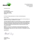
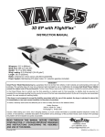
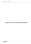
1
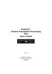
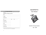
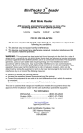
Personal Exploration Rover 2004
User Manual v1.8
Personal Rover Project
Toy Robots Initiative
The Robotics Institute
Carnegie Mellon University
PERSONAL EXPLORATION ROVER NOMENCLATURE
IR Rangefinder
Rover Head
Rover Camera
Solar Panel
UV Light
Right Rocker
Steering Servos (4)
Drive Motors (4)
Differential Axle
http://www.cs.cmu.edu/~personalrover/PER
2
TABLE OF CONTENTS
1. Software and Wireless Setup
4
2. Rover Care and Feeding
6
3. Exhibit Program Notes
8
4. The Rover Startup Self-Test
10
5. Startup Demos
12
5. Diagnostic Program Notes
12
6. Personal Exploration Rover Troubleshooting
13
7. Acknowledgments
16
http://www.cs.cmu.edu/~personalrover/PER
3
1. SOFTWARE AND WIRELESS SETUP
DOWNLOADING ROVER EXHIBIT AND DIAGNOSTIC SOFTWARE
When we install the Personal Exploration Rover (PER) at your site we will also install the Exhibit and
Diagnostic software and configure your computers’ wireless connections so that they can communicate
with the Rovers. However, in the future you may want to repeat this process to cleanly reinstall a machine
or to enable another machine to communicate with the rover. The easiest way to install Rover software on
a new computer is to make use of the CD’s we have supplied to you which contain the software.
INSTALLING SOFTWARE ON A COMPUTER
There are two software units that you need in order to use the Rover from a computer:
•
•
Java Runtime Environment (JRE): J2SE v1.4.2
PER software package
All of the code you need to install for the Exhibit and Diagnostic programs is written in Java. For this
reason, you must download and install the J2SE v1.4.2, which we have supplied to you on CD and which
you can also obtain by going to Sun’s Java site at: java.sun.com/j2se/1.4.2/download.html. An important
step after installing the JRE is to ensure that your computer’s paths’ are set up correctly to enable Java to
be used straightaway. You should be able to open a Command window and at the DOS prompt enter:
java –version
If this results in an error message then either Java is not installed or the paths are not set correctly. See
Sun’s website for help.
Our software assumes that your hard drive is C:\ and will only function properly if this is true. The
directory structure for our software places all Exhibit and Diagnostic program software in
C:\PERFilesystem. Our PER software CD contains the actual PERFilesystem directory literally on the
CD. You can copy this entire directory to your C:\ drive. Note, do not put it on your desktop; put it
directly in C:\. An alternative that you have is to copy the PERSoftware.zip zip file from the CD to your
C:\ drive, then extract all from that zip file. It will automatically create the PERFilesystem folder and
populate it appropriately. Once you have the C:\PERFilesystem folder on your computer, open the
PERFilesystem folder and note the two batch files used for launching the Exhibit and Diagnostic
programs: Run Exhibit.bat and Run Diagnostic.bat. Create shortcut copies of these and place them on
your desktop for easy access.
To verify that the programs are executable, you can go ahead and double-click on either file (Run
Exhibit.bat or Run Diagnostic.bat) to verify that Java runs and that the programs execute. You will be
greeted by the program’s first screen, and since you have not set up wireless, you can go no further. You
should terminate execution after verifying that the programs do start running. If you get an error message
about ClassNotFound, then you have a CLASSPATH specification on your machine for Java that you
don’t need and need to not have, for this version of Java, probably due to QuickTime. Go to Environment
Variables (located at Control Panel >> System >> Advanced tab) and make sure that there is no
CLASSPATH defined. If there is delete it!
http://www.cs.cmu.edu/~personalrover/PER
4
WIRELESS SETUP
Wireless configuration of your computer must be set up by an administrator or computer user familiar
with wireless settings. Remember that the Rover defaults to Ad-Hoc (Peer-to-Peer) wireless mode, so
unless you have made special arrangements with us you should not attempt to place the Rover on your
local wireless network.
All Rovers use the same SSID or Wireless Network Name, RoverNet, and have individual, fixed IP
addresses. You will be configuring your computer to operate in Ad-Hoc, Peer-to-Peer mode on the same
SSID and also with a fixed IP address. We will specify a range of IP addresses for setting your computer
to that will not collide with any Rover. Details of your computer configuration are:
•
•
•
•
•
Wireless mode: Ad-hoc or Peer-to-peer
SSID: RoverNet
IP Address: set kiosk statically to any number between 192.168.2.1 and 192.168.2.49
Subnet mask: 255.255.255.0 (the default)
No encryption or security is enabled
Once you have completed wireless configuration and have installed Rover software, you should test your
computer-rover communication setup by turning on a Rover (and waiting for it to nod), then launching the
PER Diagnostic program. Enter the IP address of the Rover. On the side of the Rover near the main
power switch and also on the electronics inside the main chassis (underneath the Solar Panel) you will find
a small label with the Rover’s number. This number, which is between 50 and 99, is the final two digits
of the IP address as follows: 192.168.2.XX. For instance, for PER 55 you would enter 192.168.2.55 in the
IP field. Enter the appropriate number for your Rover and then press Connect to verify communication.
Note: The combination of the Exhibit or Diagnostic program and knowledge about the IP addresses
of the Rovers would enable a hacker to physically come to a museum and hack into a Rover. It is
not possible to hack into the Rovers from afield, however. In order to maintain some barriers to
hacking, please do not give out the SSID network name or the IP address numbering system of the
rovers. Withholding this information will stop the most amateurish hackers.
http://www.cs.cmu.edu/~personalrover/PER
5
2. ROVER CARE AND FEEDING
MORNING VISUAL INSPECTION
We recommend a quick check of each Personal Exploration Rover at the start of each new day. There are
two major potential problems to look for in such visual inspections: loose screws and broken/pinched
wires. The following checklist will help you inspect the most critical parts of the rover:
•
•
•
•
•
•
•
•
Wheels tight: little or no play when each wheel gently twisted
Steering servos engaged: very gently steer each wheel a slight amount
Motor wires connected: inspect red and black wire connection on each motor
Rocker screws tight: check main rocker screw to differential axle by hand
Differential engaged: check rover rocking back/forth – should be small
Rover Head servos engaged: gently push head a small amount in pan and tilt
Interior inspection: lift solar panel and ensure that wireless card appears seated
Interior inspection: lift solar panel and ensure that battery wires go to power board
POWERING UP THE ROVER
When powering up the rover, you should observe several cues to verify that all is well. First, as you push
up the rocker switch (located on the side of the rover chassis box), both visually check that the power
switch indicator glows green and listen for the initial servo “twitch” from power-up. Next, wait
approximately 35 seconds. The Stayton is the main Rover processor and is the board directly underneath
the battery pack. When this on-board processor, which is running the Linux, has finished booting the
rover will notify you that it is ready for use by nodding its head and finishing in the head straight-ahead
position. Note this position. If the head is not aligned reasonably well, then the pan or tilt servo may be
in distress, or there may be a wire that is caught. In this case turn off the rover and manually verify range
of motion by moving the head with your hand before trying again. If the problem persists but range of
motion is fine, try directly commanding pan and tilt from the Diagnostic program. As the rover powers up
and enters the boot sequence the green LED’s on the wireless card plugged into the internal Stayton board
(directly underneath the battery pack) will begin blinking. This verifies that the rover is ready to
communicate and that the wireless card is plugged in and finally that the Stayton is successfully booting.
ALL ABOUT BATTERIES
The battery pack of PER consists of four 7.2V 3000 milliamp-hour NiMH (Nickel-Metal Hydride)
batteries commonly used in R/C car racing. The battery pack connects these four batteries in series, using
the same Tamiya connector as is commonly found on such batteries, yielding single battery that has about
3 amp-hours at 30 volts. Within the rover’s power system this 30 volt source is regulated efficiently to all
of the required subsystem voltages. This is one commercially available battery you can order:
Epic 3000mAh NIMH Battery Pack with Tamiya connector ($18.99 ea.)
Tower Hobbies Stock Number LXERB5 ; www.towerhobbies.com
Manufacturer Stock # EP0007
http://www.cs.cmu.edu/~personalrover/PER
6
Note that you can always check the battery pack voltage using the Diagnostic program. When performing
such a check remember that a robot standing still puts less load on the batteries than a robot moving in the
Mars Yard, and therefore your static voltage measurement is an optimistic measure of voltage. When
battery voltage approaches 26 volts or less your batteries are well below their 7.2V nominal charged
voltage and you may consider them discharged. The rover exhibits a special behavior when the
batteries are failing: it raises is head to an extreme “up” tilt position.
When inserting new batteries always switch off the rover first, so that when you plug in the new
battery pack there are no sparks. Once the new batteries are connected, then close the solar panel
paying attention to wires and connector placement and then switch the power on and verify that the power
LED lights. When you close the Solar Panel, always use the captive thumbscrews to tighten the
Panel so that, in the event of an accident, all electronics are safe. Charge batteries using the power
supply and charger we have supplied to you. Sourcing information for the power supply and charger are:
Charger: Astro Flight, Inc. 112 Deluxe Charger (1-40 cells, 50 mA – 8 Amps)
Power Supply: Astro Power Supply Model #120 (13.8V at 12.5 Amps)
Note that we supply you with one power supply because it has sufficient capacity to provide current to
two chargers. This is a single point of failure risk. If the power supply fails you must provide 12 volts, 8
Amps power to a single charger to enable charging. An automotive battery is a good temporary solution
in a bind.
To charge a battery pack, ensure that the power supply is plugged into a wall outlet, then plug the battery
into the attached charger plug. There may be a brief spark which is alright. The charger automatically
detects that you have attached a battery and will immediately begin charging. Note that if you plug in
the battery pack before plugging in the power supply, the battery will be discharged rather than
charged.
Note the Amps Adjust knob and the Amps displayed on the digital readout. Adjust the charger knob to
read approximately 2.1 Amps during charging. Anything lower than 3A is safe and at 2.1A the battery
should fully charge in approximately 3 hours. Note that the display also shows charging voltage. This
charger is a peak-detector, which means that it fast-charged your NiMH battery pack until the measured
voltage peaks and begins to fall as the pack heats up. At this point the charger knows the battery pack is
fully charged and stops, writing a message on the screen that includes total charge time and total amphours of energy input. Here is an example:
Peaked @ 35.55 V
3:10:08 3.475 AH
Total operation endurance for the Personal Exploration Rover ranges from six hours to more than ten
hours, depending upon use profiles. If the battery charger indicates an error, just power cycle it.
THE UV FLUORESCENT TUBE
The UV blacklight tube will become dim after extended use and will therefore become less effective at
activating the UV fluorescing paint on your target rocks. These are 6 inch, 4 watt black light blue (blb)
bulbs often called F4T5BLB. One source:
www.herbach.com
code: TM98UVL3225 ; $3.95 ea.
http://www.cs.cmu.edu/~personalrover/PER
7
3. EXHIBIT PROGRAM NOTES
The Exhibit program is your prime interface for use with the Mars Yard installations. The Exhibit
program can also be used as a demonstration application on the road, even if you have no satellite map
and Mars Yard to accompany it. For this mode, a special map should be loaded. Details are in this
section.
The Exhibit program should have a shortcut called RunExhibit.bat on the desktop. The program itself is
also accessible if you go to your hard drive location: C:\PERFilesystem. In this directory there is also a
copy of PERExhibit.bat on which you can double-click to launch the exhibit.
The Exhibit program will display best when the computer monitor resolution is set to 1024 by 768 pixels.
The Exhibit program is a full-screen Java program, so once you launch this application you should ensure
that a hidden keyboard is attached to the computer for program termination. To terminate the program
you would hit the Esc key on your keyboard and then confirm the process as appropriate on-screen. Once
you launch the Exhibit program, a setup dialog is displayed with two tabs. Both of these tab screens are
below:
Figure 1: Setup dialog tabs for the Exhibit program
You should always check to ensure that the IP address you enter in the Connection tab correctly matches
the Rover you intend to communicate with. If you then press Begin you will launch the Exhibit software
fully. To later leave the exhibit software, begin by pressing the Esc key.
http://www.cs.cmu.edu/~personalrover/PER
8
You also have the capability of making a number of changes using the Advanced tab. You can change the
timeout which governs how long the software waits in the Mission Central screen before returning to the
Attract Loop due to inactivity. You can also change the total time spent waiting at mission completion.
In addition, you use the Advanced tab to select the specific overhead satellite map consistent with the
Mars Yard that you are using on this particular kiosk. Therefore, the selected image must match the
intended Mars Yard. The first time you launch the Exhibit program, you must specify a set of
satellite files before proceeding. In order to use a specific map, you must specify the map image itself, a
border file and a coordinates file. All of these are required and must be consistent with one-another in
order to enable proper operation of the Exhibit software. Always put all of these files in
C:\PERFilesystem\PER\Exhibit\SatelliteMaps. Details about the contents of each file type follows:
Satellite Map File. An overhead view of the Mars Yard in jpg, gif or png format. Any size is acceptable,
but the overall file must be square (width equals length). This does not, of course, mean that the Mars
Yard need be square. Light grid lines across the image will help exhibit users identify the image as a map.
The border should be checkered with alternating solid color and transparent sections and a 1 pixel black
line edge.
Rollover Border File. An image file of type jpg, gif or png. This image should be 2 pixels shorter than
the satellite map in both the x and y direction. An entirely white image will work if you have a
rectangular satellite map. For irregularly shaped yards the border image should be white where the yard
would be and transparent elsewhere.
Coordinates File. This is a .txt text file of the following format:
numMapPoints
4
0
0
331 0
331 331
0 331
sun 331 75
yardWidthInFeet 12
The first number (4) is the number of points needed to define the Mars Yard’s shape (4 in this case for
a rectangular Mars Yard). The next four rows are (x,y) corners of the Mars Yard, expressed in pixels
that match the satellite map image pixels. Note: the origin is at the top left of the image, with x
increasing to the right and y increasing down. These points must be in order around the Mars Yard
as shown. The sun specification places the sun along the border of the yard. In this case the sun is
against the right edge of the Mars Yard, part of the way down from the top right corner. This line is
optional and can be left out if you do not want a sun marked in the interface. Finally,
“yardWidthInFeet <width>” or “yardWidthInInches <width>” or “yardWidthinCentimeters <width>”
is used to establish scale just along the x dimension. The number entered for <width> must be a
decimal number (e.g. 12.25).
An alternative to using the correct overhead map is to specify no satellite map so that the Personal
Exploration Rover can be demonstrated on the road, for instance when not in a Mars Yard. The distance
you want the Rover to travel must still be specified, and so we have a special set of files you can use to
create a distance chooser graphic in lieu of an overhead map. In order to switch from your specific Mars
Yard to this distance graphic, use the following files, which are all located at
C:\PERFilesystem\PER\Exhibit\SatelliteMaps:
Satellite Map File: justdistance.gif
Rollover File: justdistance-rollover.gif
Coordinates File: justdistance-coords.txt
http://www.cs.cmu.edu/~personalrover/PER
9
4. THE ROVER STARTUP SELF-TEST
The PER has a diagnostically useful self-test that you can trigger when you turn on the Rover. This selftest verifies that all on-board motors function, that the camera functions, and that the IR Rangefinder and
UV light are operating correctly. Here are instructions for triggering and using the Rover self-test:
•
Verify that PER is powered off when you begin, then power PER on and be ready nearby.
•
As soon as PER nods its head (35 seconds after you power up the rover), booting has completed.
You have 5 seconds after the nod is complete to put your finger directly over the camera.
•
If you have succeeded in triggering the self-test, at this point the wheel servos will begin to jitter.
Now remove your hand from the camera.
•
The rover will power on the UV light during this portion of the self test as well.
•
The rover will pan its head. Note the extreme positions; they should be +/-90 degrees and straight
ahead.
•
The rover will tilt its head to approximately +45 and -45 degrees, then straight ahead.
•
The rover will individually move each steering servo to +/- 90 degrees and then finish straight
ahead.
•
Next the rover will test all four drive motors together, ramping up and down forward speed then
repeating in the reverse direction. During this portion and the steering servo portion it is a good
idea to lift the Rover off the ground so that unnecessary stress is not put on the servos and motors.
•
After the motor forward/backward test, the rover enters Leash mode for testing the infrared
rangefinder, which is mounted next to the camera. Place the rover on a flat floor then place a
large object (e.g. the wall, a piece of cardboard) in the rangefinder’s optical path about 30 cm
from the rover. The rover will attempt to keep the object the same distance away, so you can
move the object slowly forward or backward and watch the rover correct purely in the
forward/backward directions. If the IR rangefinder is working well, the behavior will be
consistent and as expected. If the rangefinder has failed (or if its wires are broken), then this
Leash demonstration will behave quite poorly. Remember during these tests that your hand must
be in the narrow optical path of the rangefinder, and that its range is limited overall to between
approximately 10 cm up to 1.5 meters.
•
Cover the camera with your hand again to turn off the self-test program and proceed to the demos
described in section 5 below. The self-test program will also terminate leash mode if a command
is sent to the robot.
You can download a video demonstrating actuation of the cookie and the resulting rover motions at our
website, www.cs.cmu.edu/~personalrover/PER. Go to the Gallery section of our website.
http://www.cs.cmu.edu/~personalrover/PER
10
Restoring Peer To Peer Mode
Version 2.0 of the rover’s onboard Stargate/Stayton code introduces a new feature that allows you to
change which network the rover is connected to. For this to work, your rover must have the second
version of the onboard scripts installed as well as a default Peer-To-Peer IP address specified. All Stargate
boards, as well as some of the Staytons, have the correct scripts and a default IP address.
To set the network, put the rover into self-test mode as before. Wait for the rover to move its pan and tilt
servos.
To put the PER into Peer-To-Peer mode, cover up the camera while the rover tests its front two steering
servos. If everything works, the rover will move to its right when it tests its motors. This means that the
rover is in Peer-To-Peer mode on RoverNet with its default IP address (generally 192.168.2.xx). If you
correctly covered up the camera, but it wasn’t able to correctly set the network for Peer-To-Peer, the rover
will set the motors to the right at a 45 degree angle.
To make it so that the rover will connect to CMU’s network, cover up the camera while the two rear
wheels are being tested. The rover will try to connect to the CMU network with DHCP on. If successful,
the rover will move to its left while testing the motors. If the camera was correctly covered up, but
changing the network failed, the rover will move to the left at a 45 degree angle.
When covering up the camera to switch networks, you must only cover up the camera when necessary.
For example, if you cover up the camera when the front left, front right, and back right servos are being
moved, nothing will happen. When you cover up the camera while the steering servos are moving, the
UV bulb will flash on and off to let you know you have successfully covered up the camera. In this new
version of the self-test program, the UV bulb will be on while the rover is in leash mode. The UV bulb
turns off when you exit leash mode.
During the self-test the wheels turn one at a time beginning with the front
left wheel and moving counter clockwise around the rover. To switch to peer
to peer mode, cover the camera while the front wheels are moving and not
while the back wheels are moving.
http://www.cs.cmu.edu/~personalrover/PER
11
5. STARTUP DEMOS
On rovers running version 3.0 or later of the Stargate firmware, the self-test described in the previous
section is followed by two demos. To access the demos, enter self-test mode as described above. Once the
rover has finished the self-test and is in leash mode, cover the camera until the rover twitches its wheels.
This indicates that the first demo has been triggered.
Demo 1 – Wall Follow
The first demo is wall following. The rover will find a wall and follow along it, keeping the wall on the
rover’s left.
To stop the first demo and move to the second demo, cover the camera until the rover twitches its wheels.
Demo 2 – Line Follow
In the second demo the rover will follow a white line on the floor or follow a white piece of paper held at
floor level in front of the rover.
To stop the line follow demo and return to the regular mode of operation, cover the camera until the rover
twitches its wheels. You many need to keep the camera covered for about five seconds before the wheels
will twitch.
http://www.cs.cmu.edu/~personalrover/PER
12
6. DIAGNOSTIC PROGRAM NOTES
The Diagnostic program is an excellent tool for checking the Rover’s status and for demonstrating the
rover both in meetings and in educational settings. It enables you to manually drive the rover, like a
remote-controlled, teleoperated vehicle, and to grab images from the rover’s camera at will. It also
enables you to directly toggle the ultraviolet (UV) light on and off, which is useful for testing the
effectiveness of fluorescence on your target rocks.
The Diagnostic program should have a shortcut called RunDiagnostic.bat on the desktop. The program
itself is also accessible if you go to your hard drive location: C:\PERFilesystem. In this directory there is
also a copy of RunDiagnostic.bat that can be double-clicked to launch:
Figure 2: Diagnostic program screen
The most important aspect of the Diagnostic program is that you can verify both the last command you
have sent to PER and the precise result of that command by looking at text next to the labels, Last
Attempted Action and Result of Last Action. Every action that you take using this interface is documented
in this fashion, helping greatly during diagnostic evaluation of a problematic rover.
As with the Exhibit interface, enter the IP address (rather than a name) in the IP address field and press
Connect first. Result of last Action will show Connected only when two-way communication with the
Rover is successfully established. The UV on/off radio buttons enable you to manually test the UV light.
Always verify that you have turned the UV light off before leaving the Diagnostic program. Voltage is
especially useful as a running average of the battery pack voltage level.
Find Rock mimics the complete rock scanning and approach algorithm and is therefore useful both for
demonstrations and for verifying that your target rocks are of the appropriate size and shape for
autonomous detection.
Take Picture verifies that the camera is functioning correctly and allows you to simultaneously test the
Pan and Tilt degrees of freedom of the Rover head. Values are specified in degrees, with 0 straight
forward and positive degrees to the left for pan and up for tilt.
Finally, the rectangular area at the bottom left enables you to “joystick” the Rover directly, demonstrating
three different types of motion. Experiment with this. Hold the mouse button down to move and release
to stop the PER. The location of your mouse within the rectangle governs speed and rotation rates.
http://www.cs.cmu.edu/~personalrover/PER
13
7. PERSONAL EXPLORATION ROVER TROUBLESHOOTING
GENERAL TROUBLESHOOTING STRATEGY
This section provides guidance regarding first steps in diagnosing unknown rover failures. Following this
section is a list of possible specific failures and their symptoms.
Step 1: Reset and fresh power
Replace rover batteries with fresh batteries and power cycle the rover and the computer.
The simple steps above ensure that low batteries or a Windows crash are detected early.
Step 2: The twitch test
Turn off the rover, then pay attention to the sound and motion of the rover when you turn it on. If it
twitches rapidly when turned on, then the power system is intact. If there is no sound, no green power
indicator light and no twitch, then there is a power problem. If this is the case, see if the battery power
cable is broken off the power board. Lift the solar panel and follow the battery cable down to its board
and verify that it is connected.
If the Rover passes this test, the next step involves understanding whether there is a communication
problem between the computer and rover or whether there is an electrical/mechanical problem on the
rover. If the rover moves at all (whether from the Exhibit software or the Diagnostic software) then
communication is OK. In this case skip Step 3. Otherwise, first verify that you are definitely using the
correct IP address for the rover. You will feel silly otherwise!
Step 3: Use the Rover Startup Self-test
Of course you should try the Rover Startup Self-test program to verify that all is well with the Rover
locally. Note that this does not verify that the wireless communication works, however!
Step 4: 802.11b wireless card green blinkers
Open the solar panel and look at the 802.11b wireless card attached to the Stayton board (directly
underneath the battery pack). With rover power on, green lights should be blinking. If not, it may be that
the board needs to be reseated into the rover or the rover may need to be restarted. Also, when battery
voltage is low the wireless card is often the first thing to go, and this causes all communication with the
rover to fail.
Step 5: The swap test
Another very important task is to figure out if the failure is on the rover or on the computer. It is likely in
just one of the two places. So, assuming you have another kiosk and another rover that work well, try
swapping rover partners. See if the problem moves with the rover or stays with the kiosk. If the problem
stays with the kiosk you should check the wireless settings (and of course you should try rebooting the
kiosk computer). Try running the other software (if you were trying Exhibit, try Diagnostic).
http://www.cs.cmu.edu/~personalrover/PER
14
Step 6: Careful evaluation
By this time, your rover moves but does not behave well. The batteries are alright and communication is
clearly taking place. Using the Diagnostic program, carefully go through every motor that PER has to
verify that it works and thus doesn’t have a broken wire. Test the UV light and the IR Rangefinder sensor.
Test the camera and the range of motion of the head. A good checklist follows:
•
•
•
•
•
•
•
•
•
•
Battery voltage is above 20V
Every wheel motor works (hold in air)
Every steering servo works
Pan servo works +/- 180 degrees
Tilt servo works +45 / -30 degrees
Camera images are OK
Rangefinder returns consistent values
UV light on/off operational
Rocker differential and bogie joints move freely
Visual inspection for broken wires, trapped wires
SPECIFIC FAILURE / SYMPTOM LIST
Rover refuses to boot or boots only some of the time
Occasionally the daughter board on the Stargate board based robot separates slightly from the mainboard.
This won’t happen on the Stayton based robots, which have numbers in the fifties and sixties. Another
way to identify a Stargate is it uses a short compact flash based wireless card instead of the longer pcmcia
wireless card. If you have a Stargate based robot and it exhibits this problem, remove the plexiglass cover
below the battery pack, and pull up the Stargate board below it. On the end opposite the wireless card
you’ll see a small white connector between the two circuit boards. Gently press the boards together and
then replace the board and cover.
Software fails to execute
If you get an error message about ClassNotFound when you try to run any of the PER software, then you
have a CLASSPATH specification on your machine for Java that you don’t need and need to not have, for
this version of Java, probably due to QuickTime. Go to Environment Variables (located at Control Panel
>> System >> Advanced tab) and make sure that there is no CLASSPATH defined. If there is delete it!
Pan/Tilt head servo partial or total failure
If panorama images do not look correct, inspect the robot while it is performing a panorama using the
Exhibit software. Is the head twisting as far as it should? If it is not moving at all, then a servo may have
completely failed. If it is struggling, a servo may have broken gears or the head may be pinching wires.
IR Rangefinder failure
If the rover is not approaching target rocks well or is running into obstacles or is stopping short on
traverses, claiming that an obstacle is in its path, then the IR Rangefinder or the cable running to it may be
at fault. One failure for these rangefinders is that the solder joints where the three wires connected to the
http://www.cs.cmu.edu/~personalrover/PER
15
back of the rangefinder are brittle. To check for this, use the Diagnostic program. Remember that its
range is limited both by a large minimum (about 20 centimeters) and by a maximum (about 150 cm).
Steering servo appears to spontaneously lose calibration
If one or more of the steering servos appears to become suddenly miscalibrated by as much as 45 degrees
the problem may be that the servo was turned too far. Before trying to calibrate the servo with the
calibration program, turn the servo by hand (hard) all the way in one direction and then seeing if the
problem goes away. Also try the other direction. The new TS-59 servos don’t appear to exhibit this
problem, only the original GWS servos.
Wheel drive motor, steering servo or motor wire failure
If the rover is turning inaccurately or is pulling to one side during driving, it may be that a drive motor is
broken or a drive motor wire is broken. Lift the rover off the ground and command it to drive forward
using the Diagnostic program. Do all four wheels spin as appropriate or does one of them fail to do so?
During Diagnostic program use, do all four steering servos turn 90 degrees in both directions?
UV Light fails to light during Exhibit use
First, try swapping the UV Bulb with that of another Rover that verifiably works (use the Diagnostic
program for testing this). If the failure travels with the bulb, then it is simply burnt out. If the problem
remains with the Rover, then there is either a power electronics problem or the power wires leading to the
UV bulb retainers are not properly seated.
Head pointed straight up at ceiling
The rover’s batteries are low. Switch to a fresh battery pack.
Battery is dead and nothing happens when it is put on the charger
When the battery is allowed to discharge too much, such as if the rover is accidentally left on over night,
the charger will not recognize the battery. The best solution is to take another battery pack, put it on the
charger briefly, remove it and place the dead battery on the charger.
http://www.cs.cmu.edu/~personalrover/PER
16
8. ACKNOWLEDGMENTS
The Personal Exploration Rover is the product of collaboration between a large group of researchers,
engineers and developers within the Carnegie Mellon Robotics community and beyond. The following is a
list of some of the most critical team members and their roles:
Illah Nourbakhsh, Project Head, CMU Robotics
Emily Hamner, Interface Development and Project Coordinator, CMU Robotics
Eric Porter, Rover Firmware and Autonomy, CMU Computer Science
Peter Zhang, Rover Assembly Coordinator, CMU Robotics
Zeus Castro, Rover Wiring and Assembly, CMU Robotics
Michael Blain, Interface Development, CMU Computer Science
Thomas Hsiu, Rover Mechanical Design, Gogoco LLC
Botrics Inc., Rover Control Electronics
(Tom Lauwers, Brian Kirby and Chris Atwood)
Skip Shelly, Interaction Design and Graphic Design, LotterShelly
Mark Lotter, Interaction Design and Graphic Design, LotterShelly
Our sponsors, NASA/Ames Autonomy and Intel Corporation
Our exhibition partners:
The National Science Center
The San Francisco Exploratorium
The Smithsonian Air & Space Museum
NASA/Ames Visitor’s Center
http://www.cs.cmu.edu/~personalrover/PER
17