1
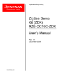
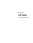
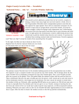
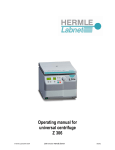
Applications Engineering
Powerful Processors – Easy to Use™
RF Sniffer
User’s Manual
Rev. 1.1
December 2006
www.renesas.com
Applications Engineering
Table of Contents
1.0 Kit Overview............................................................................................................................................ 3
2.0 RF Sniffer Interface USB Dongle ........................................................................................................... 4
3.0 RF Sniffer Software ................................................................................................................................ 5
3.1. Drop Down Menu Items..................................................................................................................... 5
3.1.1. File Menu..................................................................................................................................... 5
3.1.2. Sniffer Menu ................................................................................................................................ 5
3.1.3. Capture Menu.............................................................................................................................. 6
3.1.4. Display Menu............................................................................................................................... 6
3.2. Main Screen Buttons ......................................................................................................................... 7
3.3. Capture Windows .............................................................................................................................. 8
3.3.1. Column Layout Window .............................................................................................................. 8
3.3.2. Display Filter Window.................................................................................................................. 9
3.4. Graphical Topology Window.............................................................................................................. 9
Appendix A.
Software Installation ......................................................................................................... 11
Appendix B.
Driver Installation.............................................................................................................. 12
Appendix C.
Troubleshooting Guide ..................................................................................................... 13
C.1 Manual Installation ........................................................................................................................... 13
C.2 Driver Problems ............................................................................................................................... 13
Appendix D.
Reference Manuals .......................................................................................................... 15
RF Sniffer User’s Manual Rev 1.1
December 2006
Applications Engineering
1.0 Kit Overview
Figure 1-1: RF Sniffer Interface USB Dongle
The ZigBee RF Sniffer Interface (RFSI) is a USB Dongle made by Integration. The RFSI is a 2.4GHz RF
receiver that connects to a PC’s USB port.
The RF Sniffer software runs on a PC with Windows O/S. The software allows you to analyze RF
communication packets and protocol in a ZigBee network. You can also display a graphical
representation of the ZigBee network topology.
Figure 1-2: RF Sniffer Software Capture and Topology Windows
RF Sniffer User’s Manual Rev 1.1
3/ 15
December 2006
Applications Engineering
2.0 RF Sniffer Interface USB Dongle
NOTE: The following chapters assume that you installed the required ZigBee Demo Kit software and USB
drivers while following the QuickStart guide, parts 1 and 2. Please see Appendix A and Appendix B for
software and driver installation details, if required.
1. Connect the RF Sniffer Interface (RFSI) USB dongle to a free USB port on your PC.
2. Start the RF Sniffer software (Start > All Programs > Renesas > RF Sniffer V.x.xx > RF Sniffer).
3. Click the Connect button on the RF Sniffer Software Toolbar. It changes its color to blue and
displays “Disconnect” now instead of “Connect”. The channel selector to the right should be set to
channel 24 (0x18). The RFSI’s red LED will come on when the software connects.
Figure 2-1: RF Sniffer Software Toolbar
4. Click the Capture button. The RF Sniffer software is now in capture mode.
While in capture mode, the RFSI’s red LED will blink whenever a new data packet is received.
RF Sniffer User’s Manual Rev 1.1
4/ 15
December 2006
Applications Engineering
3.0 RF Sniffer Software
The RF Sniffer software allows you to protocol and analyze RF communication packets in a ZigBee
network. You can also display a graphical representation of the ZigBee network topology. This chapter
explains the features of the software.
3.1. Drop Down Menu Items
3.1.1. File Menu
Figure 3-1: File Menu
Open
Save As…
Exit
Open a file with previously captured ZigBee protocol data.
Save the current captured ZigBee protocol data to a file.
Quit the RF Sniffer Program.
3.1.2. Sniffer Menu
Figure 3-2: Sniffer Menu
Connect
Disconnect
Info
Connect to the RF Sniffer hardware.
Disconnect from the RF Sniffer hardware.
Display RF Sniffer hardware Info (firmware revision, type of sniffer board).
RF Sniffer User’s Manual Rev 1.1
5/ 15
December 2006
Applications Engineering
3.1.3. Capture Menu
Figure 3-3: Capture Menu
Start Capturing
Stop Capturing
Capture Filter
Start capturing ZigBee network traffic.
Stop the capture process.
The capture filter allows you to filter for specific source and destination
addresses, remove ACK and command packets, and to show packets
with bad CRC.
3.1.4. Display Menu
Figure 3-4: Display Menu
Column Layout
Display Filter
Time Units
Delta Time
Auto Scroll
Define the column display order in the capture window and select which
items are displayed.
Select which ZigBee packet types to display: ACK, Command, Beacon,
Data, Bad CRC packets.
Display time information in Microseconds, Milliseconds or Symbol Length.
Define how the Delta Time between two successive ZigBee packets is
measured: From the beginning of a packet to the beginning of the next
packet, or from the end of previous packet to the beginning of the next
packet.
With Auto Scroll selected, the capture window will automatically scroll
down to always show the latest received RF packet. When auto scroll is
deselected the capture window will remain static, new data packets are
captured, but you will have to manually scroll down to see them.
RF Sniffer User’s Manual Rev 1.1
6/ 15
December 2006
Applications Engineering
3.2. Main Screen Buttons
Figure 3-5: RF Sniffer Main Screen Buttons
Connect/Disconnect
Capture
RF channel
Protocol Layer
Clear
Graphical Topology
Toggle button to connect/disconnect from the RF Sniffer hardware.
Clicking the white Connect button will establish a connection to the
Sniffer hardware. The button’s color will change to blue and its text to
Disconnect. Clicking the blue Disconnect button will disconnect the
Sniffer software from the hardware.
Toggle button to start/stop the ZigBee network traffic capturing process.
Clicking the white Capture button will start the capture process. The
button’s color will change to blue and its text to Stop. Clicking the blue
Stop button will end the capturing process.
Drop-down selection menu to select the ZigBee RF channel. The
channel number is displayed in both decimal and hexadecimal values.
The default channel used by the ZDK boards is channel 24 (0x18).
Four selection buttons, labeled MAC, NWK, APS and ZDO allow you to
determine the type of ZigBee protocol layer shown in the capture window.
The current selected layer’s button is colored blue. Selecting MAC will
show the raw data transmitted at the Medium Access Control Layer
(IEEE 802.15.4 RF layer specification). Selecting NWK displays data at
the ZigBee network layer. APS stands for ZigBee application layer and
ZDO for ZigBee Device Object layer. The current version of the software
does not yet support displaying data at the APS and ZDO layer levels.
Pressing the Clear button clears the content of the RF Sniffer capture
window.
Opens a new window with a graphical representation of the ZigBee
networks topology. Note: For the software to be able to display the
graphical topology of the network, the RF Sniffer software must be
connected to the Sniffer hardware and the Capture mode must have
been started before the ZigBee network is being established, i.e. before
any ZigBee device is being switched on and joins or establishes the
network.
RF Sniffer User’s Manual Rev 1.1
7/ 15
December 2006
Applications Engineering
3.3. Capture Windows
3.3.1. Column Layout Window
Figure 3-6: RF Sniffer Column Layout Window
The Column Layout Window displays several columns of information about every ZigBee packet
received. The order of the columns and the items displayed can be changed via the Display >
Column Layout menu. The column headings in the screenshot shown in Figure 3-6 from left to
right are:
No.
The packet number.
Time
The time in absolute Microseconds from the time the very first packet was
received.
Delta
The delta time in Microseconds between the start of two packets.
Packet Type The ZigBee packet type.
Src PAN
The Source PAN (Personal Area Network) address of the transmitting ZigBee
node.
Src Addr.
Source Address. The address of the transmitting ZigBee node.
Dest. PAN
The Destination PAN address, i.e. the PAN to which the receiving node belongs.
Dest. Addr.
Destination Address. The address of the receiving ZigBee node.
Info
Information about the packet. The display in this column depends on the selected
protocol layer (MAC, NWK, APS or ZDO) and the type of packet transmitted.
Len
The Length of the ZigBee packet in bytes.
Seq.
The Sequence number of the MAC header packet.
LQI
Link Quality Indication. LQI is a calculated value between 0 and 255 with a higher
LQI number indicating a better link quality.
CRC
Cyclic Redundancy Check. ZigBee packets are transmitted with a CRC
checksum for error recognition and correction. If “OK”, the packet was received
without transmission errors.
RF Sniffer User’s Manual Rev 1.1
8/ 15
December 2006
Applications Engineering
3.3.2. Display Filter Window
Figure 3-7: RF Sniffer Display Filter Window
Figure 3-7 shows the details of the ZigBee packet # 133 that was selected by clicking on the
corresponding row in the column layout window above. The left windowpane shows the different
components of the ZigBee packet: Packet Length, MAC Header, NWK Header and NWK Payload.
The right windowpane shows the raw data bytes of the packet as both 8-bit hex values and ASCII
code. Clicking on an entry in the left windowpane will highlight the corresponding hex values in
the right pane in blue. In above example the 7-byte NWK payload is 00 00 00 01 FF AA 8C. Byte
1 = 00 indicates that a ZDK board transmits a new LED and sensor state. The next three bytes
represent the status of the red, yellow and green LEDs respectively (00 = LED off; 01 = LED on).
The next three bytes are the 8-bit analog values of the board’s potentiometer, light and
temperature sensors, respectively.
3.4. Graphical Topology Window
Click on the Graphical Topology button and a window will open showing you the ZigBee nodes that
are members of the network, how they are interconnected, and the flow of information between them.
In the example screen shot below, the node with address 0000 (the coordinator) sends a packet to
the node with address 0001.
RF Sniffer User’s Manual Rev 1.1
9/ 15
December 2006
Applications Engineering
Figure 3-8: RF Sniffer Graphical Topology Window
Topology Window Buttons:
Clear
Clear the Topology Window Display
Use CSkip
This is a toggle On-Off button. The term CSkip refers to the Child-Skip algorithm
outlined in the ZigBee specification. When this button is left "On", the topology of
the network will be determined by the source addresses of each captured packet
using the CSkip algorithm and the values of Cm-Rm-Lm button.
Cm#,Rm#,Lm# This button is used to show and set the current network configuration parameters
for the ZigBee CSkip algorithm. These values must match your current network
configuration to produce an accurate topology representation.
RF Sniffer User’s Manual Rev 1.1
10/ 15
December 2006
Applications Engineering
Appendix A. Software Installation
Before using the RF Sniffer Kit, you need to install the required software files and applications. Do not
plug the RF Sniffer Interface (RFSI) into your PC until the installation process is finished. The installer will
automatically detect prior installations of the software and prompt you to remove those before continuing.
Please insert the enclosed CD into your computer’s CD-ROM drive. The CD should auto-start, displaying
the ZigBee ZDK Install Screen. Select “ZigBee ZDK For M16C”. Follow the directions in the installation
windows to install the ZDK demo software tools and the RF Sniffer software.
If the installation screen does not appear, please browse to the CD root folder and double-click on
ZDK_Installer.exe.
Please review the QuickStart Guide, which may contain information about the RF Sniffer that was not yet
available when this user manual was printed.
If you experience problems with the install software, please see chapter “C.1 Manual Installation” in
Appendix C.
.
RF Sniffer User’s Manual Rev 1.1
11/ 15
December 2006
Applications Engineering
Appendix B. Driver Installation
Your ZigBee Development Kit includes a ZigBee RF Sniffer Interface (RFSI) USB stick. When you
connect the RFSI to your computer for the first time, Windows will recognize the new device and request
the driver. Follow the steps below to install the driver for the RFSI. Administrator privileges are required to
install the driver on a Windows 2000/XP machine.
a.) Plug the RFSI USB stick into a free USB port on your PC. The Windows New Hardware Wizard
should start.
b.) In the New Hardware Wizard Welcome screen, select “No, not this time” when the Wizard
prompts to search Windows Update for software and click on <Next>.
c.) Select “Install from a list or specific location (Advanced) and click on <Next>.
d.) Select “Search for the best driver in these locations” and place a check mark in front of “Include
this location in the search”.
Browse to C:\Renesas\RFSniffer\USB Driver\Integration Dongle and click on
<Next>.
e.) Click <Finish>.
Figure 12: New Hardware Wizard Search Path
RF Sniffer User’s Manual Rev 1.1
12/ 15
December 2006
Applications Engineering
Appendix C. Troubleshooting Guide
This section discusses possible problems you may encounter while installing the RF Sniffer software and
drivers. This section also discusses the countermeasures and solutions to resolve these problems.
For troubleshooting information on the Flash-Over-USB programming software, In-Circuit Debugger and
Renesas HEW, see the ZDK Kit User’s Manual.
If, for any reason, you cannot resolve the problem, please contact your Renesas representative for
assistance.
C.1 Manual Installation
Before connecting the RF Sniffer Interface to your PC, the driver files (.inf and .sys) and executables
must be copied to the C:\Renesas\RFSniffer\USB Driver\Integration Dongle directory.
To do this, double-click RFSniffer_V.xx.exe under \Tools\RFSniffer directory on the CD.
After the RF Sniffer install, assuming the default directory was used, a C:\Renesas\RFSniffer
subfolder should have been created. The Windows USB drivers for the RF Sniffer Interface are
located in the C:\Renesas\RFSniffer\USB Driver\Integration Dongle directory. The
driver files are: IAIDAUB1.sys and IAIDAUB1.inf.
NOTE: If you are using Windows 2000 or XP, you will need Administrator privileges to be able to
install the drivers.
(1) Windows 2000
(a). Install RF Sniffer software by double-clicking on RFSniffer_V.xx.exe from the
\Tools\RFSniffer folder of the CD.
(b). Copy
the
IAIDAUB1.inf
file
from
C:\Renesas\RFSniffer\USB
Driver\Integration Dongle folder to \WINNT\INF folder.
(c). Copy
the
IAIDAUB1.sys
file
from
C:\Renesas\RFSniffer\USB
Driver\Integration Dongle folder to \WINNT\SYSTEM32\drivers folder.
(2) Windows 98
(a). Install RF Sniffer software by double-clicking on RFSniffer_V.xx.exe from the
\Tools\RFSniffer folder of the CD.
(b). Copy
the
IAIDAUB1.inf
file
from
C:\Renesas\RFSniffer\USB
Driver\Integration Dongle folder to \WINDOWS\INF folder.
(c). Copy
the
IAIDAUB1.sys
file
from
C:\Renesas\RFSniffer\USB
Driver\Integration Dongle folder to \WINDOWS\SYSTEM32\drivers
folder.
C.2 Driver Problems
This part discusses how to fix common problems that may occur with USB driver installation. The
most common problem is that Windows did not properly install the USB drivers and so the RFSI
is not recognized. When checking the device status in the Windows Device Manager (Start >
Control Panel > System > Hardware > Device Manager > Universal Serial Bus controllers > IAIDAUBI-2400 V033), it will indicate that the device is not working properly. A further indication of
RF Sniffer User’s Manual Rev 1.1
13/ 15
December 2006
Applications Engineering
this problem is that the Sniffer software is unable to connect to the USB dongle (dongle’s red LED
does not come on).
Before trying the following steps, try re-starting your PC to see if this resolves the problem. You
can check the status using the Device Manager. If the Renesas RF Sniffer appears under the
Universal Serial Bus Controllers with no red X or yellow exclamation point, the driver was
installed properly.
For cases where the “Device Status” states the device is not working properly, please try the
following:
1.
2.
3.
4.
Double-click on IAI-DAUBI-2400 V033. A Properties dialog box appears.
Click on Driver tab and click on Update Driver button.
Select “Display a list…” and click on Have Disk button.
Locate the C:\Renesas\RFSniffer\USB Driver\Integration Dongle directory
and install the IAIDAUB1.sys driver.
5. If this process does not work, please follow the instructions below.
For cases in which the driver was not installed properly by Windows (Windows 98, Windows
2000) or is not listed in the Device Manager > Universal Serial Bus controllers, please try the
following:
1. Unplug the USB Cable so Windows removes the driver from memory.
2. Delete the driver IAIDAUB1.sys from \WINNT\SYSTEM32\DRIVERS\ folder in Windows
2000 or \WINDOWS\SYSTEM32\DRIVERS folder in Windows 98.
3. Plug in the RFSI and try installing the driver as described above, using the driver from the
C:\Renesas\RFSniffer\USB Driver\Integration Dongle directory.
RF Sniffer User’s Manual Rev 1.1
14/ 15
December 2006
Applications Engineering
Appendix D. Reference Manuals
Item
Title
Description
1.
Renesas ZigBee Demonstration Kit
(ZDK)Quick Start Guide
Document that will help you get started on using the
ZigBee demonstration Kit.
2.
3.
RF Sniffer User’s Manual
ZDK Board Schematic
4.
5.
7.
ZDK Board BOM
M16C/20/60
Series
C-Language
Programming Manual
M16C/20/60
Series
Assembler
Language Programming Manual
HEW User’s Manual
8.
9.
10.
AS30 User’s Manual
NC30 User’s Manual
RTA-FoUSB-MON User’s Manual
This document.
Schematic diagram for the RF Sniffer and ZDK
boards.
Bill of materials for the ZDK board.
ANSI C-language programming guide for the
M16C/20/60 series MCU.
Assembly language programming guide for the
M16C/20/60 series MCUs.
This document describes installation and operation
of the Integrated Development Environment for
Renesas’ Tools.
Guide for AS30 assembler.
Guide for NC30WA C-compiler.
In-Circuit Debugger and Programmer User’s Manual
6.
NOTE:
The installer will copy all these manuals during installation. They can be accessed using the Document
Descriptions file by clicking on Start > Programs > Renesas > RZB_CC16C_ZDK > All Manuals and
Documents
RF Sniffer User’s Manual Rev 1.1
15/ 15
December 2006