1
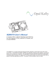
SIMPlugIN board® family
Board:
SIMPlugIN LX45
Document: User Manual
File: simplugin-LX45_user_manual_rev_03.doc
page 1 of 24
SIMPlugIN-LX45 User Manual
... a SIMPlugIN board® family member
Revision: see file name on page header
Date:
September 13th 2011
SIMPlugIN board® family
Board:
SIMPlugIN LX45
Document: User Manual
File: simplugin-LX45_user_manual_rev_03.doc
REVISION HISTORY
0.1
0.2
First release
Corrected factory default jumper configuration
page 2 of 24
SIMPlugIN board® family
Board:
SIMPlugIN LX45
Document: User Manual
File: simplugin-LX45_user_manual_rev_03.doc
page 3 of 24
0) INTRODUCTION AND REFERENCES ................................................................................... 5
0.1) References..............................................................................................................................................................................5
1) GENERAL DESCRIPTION...................................................................................................... 6
1.1) Overall block diagram..........................................................................................................................................................6
1.2 ) Power supply block diagram...............................................................................................................................................7
1.2.1) Power Input voltage and protections ...........................................................................................................................9
1.3 ) User connectors ..................................................................................................................................................................10
1.4 ) Exceptions in user connector uniformity .........................................................................................................................11
1.5 ) VREF for FPGA banks .....................................................................................................................................................11
1.6 ) Oscillators ...........................................................................................................................................................................11
1.7 ) EEPROM............................................................................................................................................................................11
1.8 ) User LEDs, pushbuttons and microswtiches ...................................................................................................................11
1.9 ) Power-on reset....................................................................................................................................................................11
1.10 ) SPI flash memory.............................................................................................................................................................11
1.11 ) FTDI USB -> serial chip .................................................................................................................................................12
1.12 ) DDR2 memory..................................................................................................................................................................12
1.13 ) JTAG interface.................................................................................................................................................................12
2) CONNECTORS ..................................................................................................................... 13
2.1 ) CON14 , power input.........................................................................................................................................................13
2.2 ) CON11, JTAG programming for standard programmers ............................................................................................13
2.3 ) CON12, SPI programming for standard programmers................................................................................................13
2.4 ) CON10, SPI and JTAG programming for SIMPlugIN programmer..........................................................................14
2.5 ) CON13, mini USB .............................................................................................................................................................14
2.6 ) CON1, CON2,…, CON9: User connectors ......................................................................................................................15
2.6.1) BANK 0 user connectors .............................................................................................................................................16
2.6.2) BANK 1 user connectors .............................................................................................................................................17
2.6.3) BANK 2 user connectors .............................................................................................................................................19
3) CONFIGURATION JUMPERS .............................................................................................. 21
3.1 ) Power supply configuration ..............................................................................................................................................21
SIMPlugIN board® family
Board:
SIMPlugIN LX45
Document: User Manual
File: simplugin-LX45_user_manual_rev_03.doc
page 4 of 24
3.2 ) Other configuration jumpers ............................................................................................................................................22
4) LEDS, PUSHBUTTONS, MICROSWITCHES, TESTPOINTS AND OSCILLATORS............ 22
4.1 ) LEDs....................................................................................................................................................................................22
4.1.1) User LEDS ....................................................................................................................................................................22
4.1.2) Other LEDs ..................................................................................................................................................................22
4.2 ) Pushbuttons ........................................................................................................................................................................23
4.2.1) PUSHB0 ........................................................................................................................................................................23
4.2.1) PUSHB1 , 2 ,3 , 4 ..........................................................................................................................................................23
4.3 ) Microswitches.....................................................................................................................................................................23
4.4 ) Testpoints............................................................................................................................................................................24
4.5 ) Oscillators ...........................................................................................................................................................................24
4.5.1) 25 MHz..........................................................................................................................................................................24
4.5.2) User oscillator...............................................................................................................................................................24
APENDICES
A) Board layout
B) Schematics
C) Bill of Materials
SIMPlugIN board® family
Board:
SIMPlugIN LX45
Document: User Manual
File: simplugin-LX45_user_manual_rev_03.doc
page 5 of 24
0) Introduction and references
This manual describes how to operate SIMPlugIN-LX45 board.
SIMPlugIN board is intended for engineers (engineering students too) that want to enjoy an easy to use and easy
to expand FPGA developpment board.
This board provides on board the essential elements
- FPGA itself (in this case: Xilinx Spartan 6 model LX45 in BGA 484 package, 2 speed grade, Comercial
temperature range)
- DDR2 memory; 64Mx16 ( 128 Mbytes), up to 300 MHz clock, 600 MHz data rate.
- SPI flash memory: 64Mbit ( 8 Mbyte ) for fpga content (a little less than 2 Mbyte) plus 6 Mbyte extra of
aditional storage (for instance for Microblaze embedded processor firmware)
- Power supply
- Console port ( USB serial device)
- A few user leds and switches
In adition to these essential elements the board offers 9 connectors with 20 fpga pins each ( a total for 180 pins
available to the user).
The connectors are standard and easy to use:
- 0.10” ( 2.54 mm) pitch
- 2x17 right angle male header
- fully polarized
SIMPlugIN board® family offers many off the self boards that inmediately expand the capability of SIMPlugINLX45 board. At the date of writing this manual there are 8 models avialable of add-on boards:
- SIMPlugIN-VIDEO video DAC to be able to implement VGA video output.
- SIMPlugIN-ETHERNET 100 with 10/100 Ethernet phy chip.
- SIMPlugIN-USB with USB 2.0 (12 Mbit, full speed) device transceiver chip
- SIMPlugIN- SD with SD card slot
- SIMPlugIN- SERIAL 1 x RS232 plus 2 x RS485 (the three interfaces can be used simultaneously)
- SIMPlugIN-LED 20 x test point plus 20 x led (both red and green led for each test point)
- SIMPlugIN-DIGIT with 2 x hex display ( 7 segment display) + 4 micro switches
- SIMPlugIN-PROT prototyping board with perforated 0.10” grid and two sided plated holes
0.1) References
Note: from time to time companies modify their web pages. So, some of the detailed web link may be obsolete when you read the present
document.
-
Many documents are available in www.xilinx.com concerning Spartan 6 FPGA. In
http://www.xilinx.com/support/documentation/spartan-6.htm there is comprehensive list of them.
W971GG6JB DDR2 SDRAM data sheet Revision A06 in www.winbond.com
W25Q64BV (64M-bit) Serial (SPI) Flash memory data sheet Revision E in www.winbond.com
Male, 2x17 pin connector (on SIMPlugIN-LX45 board) model 75867-106LF. See 75867 family data sheet
Rev:AM Dec 1 6 , 2 0 1 0 in www.fciconnect.com
Female 2x17 pin connector (on all SIMPlugIN add-on boards) model SFH11-PBPC-D17-RA-BK. See data
sheet in www.sullinscorp.com
FT232RL usb-serial chip. See datasheet and download software drivers (for Windows, Linux, Mac,…) in
www.ftdichip.com
24AA02E48T eeprom with I2C interface and unique serial number. See data sheet in www.microchip.com
SIMPlugIN board® family
Board:
SIMPlugIN LX45
Document: User Manual
File: simplugin-LX45_user_manual_rev_03.doc
page 6 of 24
1) General description
EEPROM
1.1) Overall block diagram
.
25 MHz
oscillator
VCC0-1
CON3
Symbols
user
oscillator
functional block
CON4
connector
bus
JTAG
+1.8
VCC0-2
4 user
LEDs
control signals
CON5
power supply
+3.3-INT
+1.2
FPGA
BANK1
VCC0-1
+1.8
DDR2
memory
BANK3
VCC0-0
CON1
BANK0
VCC0-0
CON13
FTDI
USB -> serial
CON2
console
4 user
push buttons
BANK2
VCC0-2
CON6
VCC0-2
CON7
4 user
micro switches
power-on
RESET
button
CON8
JTAG
CON11
SPI
flash
memory
std. JTAG
programmer
CON10
SIMPlugIN
programmer
CON9
JTAG
SPI
VCC0-0
VCC0-1
VCC0-2
SPI
CON12
std. SPI
programmer
CON14
5 volt DC
input
power
supply
+1.2
+1.8
+3.3-INT
+3.3
+5.0
SIMPlugIN board® family
Board:
SIMPlugIN LX45
Document: User Manual
File: simplugin-LX45_user_manual_rev_03.doc
page 7 of 24
1.2 ) Power supply block diagram
CON14
5 volt DC
input
+5.0
overcurrent
protection
reversal
protection
DC/DC
converter
(nominal 3 amp)
overvoltage
protection
A
B
C
+1.2
JMP23
+3.3
DC/DC
converter
(nominal 3 amp)
A
B
+3.3-INT
JMP21
DC/DC
converter
(nominal 3 amp)
VCC_CUST
JMP22
A
B
C
D
E
VCC_CUST
voltage
select
+3.3
VCC0-0
A
B
C
JMP24
VCC_CUST
VCCO-0
voltage
select
A
B
C
JMP25
+3.3
VCC0-1
A
B
C
VCCO-1
voltage
select
JMP26
VCC_CUST
A
B
C
JMP27
+3.3
VCC0-2
A
B
C
VCCO-2
voltage
select
JMP28
VCC_CUST
A
B
C
JMP29
voltage
regulator
+3.3
(nominal 1.5 amp)
A
B
JMP20
+1.8
SIMPlugIN board® family
Board:
SIMPlugIN LX45
Document: User Manual
File: simplugin-LX45_user_manual_rev_03.doc
page 8 of 24
Some jumpers should always be populated (in ALL its positions) in normal operation. Their function is to
allow the user to open the circuit and so be able to put in series ammeter(s) to monitor the current(s) of each power
supply.
:
JMP23 to monitor +1.2 power supply ( the one used by FPGA core)
JMP20 to monitor +1.8 power supply (used by DDR2 and bank 3 of FPGA chip)
JMP21 to monitor +3.3-INT (used to power VCCAUX of FPGA chip AND to feed the linear voltage
regulator that generates +1.8 power supply
Notes:
a) In adition of DDR2 and bank 3 of FPGA, +1.8 supplies a little current to FTDI chip and some
pullups (see page 4 of the schematics).
b) [current used by VCCAUX] = [current measured in JMP21] – [current measured in JMP20]
The rest of the jumpers shown in the above figure are configuration jumpers
JMP22 configures the voltage of VCC_CUST
- position A populated, all others not populated: 1.2 volt
- position B populated, all others not populated: 1.5 volt
- position C populated, all others not populated: 1.8 volt
- position D populated, all others not populated: 2.5 volt
- position E populated, all others not populated: 3.3 volt
Note: all other combinations are not harmful but are not usual. For example:
o all positions not populated: 0,75 volt (too low)
o position C and D both populated, all other not populated: 2.64 volt ( not standard)
JMP24 and JMP25 configure VCCO-0
FPGA bank 0
Asociated user connectors: CON1 and CON2
JMP24
JMP25
fully populated
completely NOT populated
completely NOT populated
fully populated
All other combinations
voltage
VCC_CUST
+3.3
ILEGAL, dangerous
DANGER !! some illegal icombinations could damage the board and/or add-on boards pluged into ANY of
user connector, even corresponding to OTHER banks.
JMP26 and JMP27 configure VCCO-1
FPGA bank 1
Asociated user connectors: CON3 , CON4 and CON5
JMP26
JMP27
fully populated
completely NOT populated
completely NOT populated
fully populated
All other combinations
voltage
VCC_CUST
+3.3
ILEGAL, dangerous
DANGER !! some illegal icombinations could damage the board and/or add-on boards pluged into ANY of
user connector, even corresponding to OTHER banks.
JMP28 and JMP29 configure VCCO-2
FPGA bank 1
Asociated user connectors: CON6 , CON7 , CON8 and CON9
JMP28
JMP29
fully populated
completely NOT populated
completely NOT populated
fully populated
All other combinations
voltage
VCC_CUST
+3.3
ILEGAL, dangerous
DANGER !! some illegal icombinations could damage the board and/or add-on boards pluged into ANY of
user connector, even corresponding to OTHER banks.
SIMPlugIN board® family
Board:
SIMPlugIN LX45
Document: User Manual
File: simplugin-LX45_user_manual_rev_03.doc
page 9 of 24
1.2.1) Power Input voltage and protections
The board must be powered with 5 volt DC with +/- 5% tolerance. A maximun current of 3 AMP ( so 15 wats) is
specified.
A cable is provided to power the board from a laboratory power supply. This cable is not standard but is composed
of standard componentes:
- 1 unit of cable assemblly with power jack.
- 1 unit of red PLUG BANANA.
- 1 unit of black PLUG BANANA.
To power the board from AC mains (if you do not have laboratory power supply) use a wall power supply unit
with 5 volt DC , 3 amp. Notice that such a wall power unit is optional and must be purchased separatedly.
Many protections are provided
-
-
Over current:
o nominal 3 amp resettable fusible proteccts 5 volt DC input
o +1.8 is current limited ( around 2.4 amp) by its voltage regulator. Also it thermally protects itself.
o +1.2 , +3.3 (that includes +3.3-INT) and VCC_CUST are independtly current limited by its
respective voltage regulator ( around 6 amp). Also each is independently thermally protected.
Voltage reversal: the input will tolerate a reversed voltage down to minus 17 volt. Any voltage bellow that
(either continous or temporary peak) will damage the board
Overvoltage: the input will tolerate up to 17 volt of DC. Any voltage about that (either continous or
temporary peak) will damage the board.
Reverse voltage symptom: the board will not be internally powered a not a single LED will be lit.
Overvoltage symtom: LD11 will be lit, all the others will not. Notice that LD11 is the only yellow led in the board,
also is the only 5 mm through hole led.
BE CAREFUL, even with those protections the board will not survive a “masive” abuse
like connecting it directly to the AC mains (even the relatively “mild” 100 AC volt mains in U.S.A)
MORE: you clearly risk FIRE if you do it.
SIMPlugIN board® family
Board:
SIMPlugIN LX45
Document: User Manual
File: simplugin-LX45_user_manual_rev_03.doc
page 10 of 24
1.3 ) User connectors
Each of the nine ( CON1, CON2,…CON9) user connectors provides 20 FPGA I/O pins plus 3 different power
supplies:
- VCCO correspondiing to its asociated bank
- 3.3 volt
- 5.0 volt
DANGER !! if the user uses 5.0 volt. in his or her custom add-on board then care must be taken that any of the 20
FPGA pins does NOT receive more than 3.3 volt since FPGA pins tolerate without problem 3.3 volt (even if the
bank is powered by a much lower voltage like 1.8 volt or 1.5 volt) but will NOT tolerate higher than 4 volt (the FPGA
chip would get permanently damaged !!). For a working example see schematics of SIMPlugIN- SERIAL board
that uses 5 volt but does not send any 5 volt signal back to FPGA pins.
With very minor exceptions (see next point bellow) the pins in the 9 user connector are distributed as shown in the
following figuere
+3.3
+5.0
JMP5
JMP6
GND
VCCO-1
GND
VCCO-1
IO_L31P_A19_M1CKE_1
IO_L31N_A18_M1A12_1
IO_L52P_M1DQ14_1
IO_L52N_M1DQ15_1
GND
VCCO-1
IO_L37P_A7_M1A0_1
IO_L37N_A6_M1A1_1
IO_L50P_M1UDQS_1
IO_L50N_M1UDQSN_1
GND
VCCO-1
IO_L41P_GCLK9_IRDY 1_M1RASN_1
IO_L41N_GCLK8_M1CASN_1
IO_L48P_HDC_M1DQ8_1
IO_L48N_M1DQ9_1
GND
VCCO-1
IO_L44P_A3_M1DQ6_1
IO_L44N_A2_M1DQ7_1
IO_L46P_FCS_B_M1DQ2_1
IO_L46N_FOE_B_M1DQ3_1
GND
VCCO-1
HEADER_17X2_MALE_R/A
IO_L19P_1
IO_L19N_1
IO_L20P_1
IO_L20N_1
CON3
1
2
3
4
5
6
7
8
9
10
11
12
13
14
15
16
17
18
19
20
21
22
23
24
25
26
27
28
29
30
31
32
33
34
See detailed complete pin-out in 2.6) point in this documents.
Notice:
- power (VCCO-? , +3.3 and +5.0) are always in the same pins in all the connectors (where “?” in VCCO-? Is
0, 1, or 2 for FPGA bank 0, 1, 2, respectively)
- pin 23 and pin 25 are always a pair of global clocks (can be used as a differencial pair or as two separated
single ended clocks).
- two connectors, CON1 and CON2 have one aditional pair of global clocks
- the 20 pins are grouped in 10 pairs that follow paired pins of FPGA (with only one single exception in
CON2, see next point bellow). The two tracks, negative and positive, of each pair have PCB tracks that are
carefully matched lenghts (notice different pairs have different lenghts, that is, the pairs are matched within
themselves but NOT with respect to other pairs).
- +3.3 and +5.0 power lines are fed to the connector through jumpers. Remove these jumpers unless you
are really using this power supplies in your custom add-on board.
SIMPlugIN board® family
Board:
SIMPlugIN LX45
Document: User Manual
File: simplugin-LX45_user_manual_rev_03.doc
page 11 of 24
1.4 ) Exceptions in user connector uniformity
Each of the nine ( CON1, CON2,…CON9) are very similar except the following differences:
-
CON2 , pins 6 and 8 do NOT correspond to a pair of FPGA pins.
CON1 and CON2 have an aditional pair of global clocks.
CON1 and CON2 are connected to FPGA bank 0 and powered by VCCO-0 (as bank 0 itself)
CON3 , CON4 and CON5 are connected to FPGA bank 1 and powered by VCCO-1 (as the bank 1 itself)
CON6 , CON7, CON8 and CON9 are connected to FPGA bank 2 and powered by VCCO-2 (as the bank
2 itself)
1.5 ) VREF for FPGA banks
Each FPGA bank 0,1,2 have a voltage divider (implemented with two 100 ohm resistors) bypassed with capacitors
that feeds all the VREF pins of each bank with its VCC0-? divided by two (where “?” is 0,1,2) . That allows the user
to select for each pin all I/O standard except HSTL_III and HSTL_III_18 (the only two I/O standard that require
VREF different to VCCO / 2 ). See Xilinx documents “Spartan-6 FPGA Data Sheet: DC and Switching
Characteristics” and “Spartan-6 FPGA SelectIO Resources User Guide”
1.6 ) Oscillators
The board ships with a 25 MHz oscillator in OSC1 position. Since it is on socket the user can easily change it but it
must be taken into account that:
- some of the FPGA examples provided suposse that this oscillator is 25 MHz if you change the frequency
the behaviour of these examples (for instance, the one that exercises the USB device interface) could stop
working (or will need a change in the example source code).
The other oscillator (user oscillator in OSC2 position) is an empty socket available to the user.
Note: the oscillator installed must be 3.3 volt , CMOS type. Notice (see schematic) that the oscillator is allways
powered by 3.3 volt. The ouput of the oscillator is fed to the FPGA thorough buffers that act as level translators into
whatever power is selected for bank 1.
1.7 ) EEPROM
EEPROM is implemented with 24AA02E48T from Microchip. The interface with this eeprom is I2C. This eeprom
provides a unique, read-only, number and identfies your board. Do not change this chip since that action would
void the warranty. The write/read part of the eeprom is fully available to the user.
1.8 ) User LEDs, pushbuttons and microswtiches
The boad provides 4 leds, 4 pushbuttons and an one microswitch with 4 position.
1.9 ) Power-on reset
The board provides one pushbutton , PUSHB0, (independent of the four user pushbuttons mentioned above).
When pressed this the signal RESET_POW_ON will be activated for about 100 msec after releasing PUSHB0.
This will allow to implement a user “power on reset.
1.10 ) SPI flash memory
The board provides SPI flash, 64 Mbit ( 8 Mbyte) memory that will contain FPGA configuration ( a little less than 2
Mbyte); that leaves 6 Mbytes for user data (for instance code and data for a Microblaze embeded processor).
It is implement using W25Q64BVSFIG Winbond chip.
The chip is always powered by 3.3 volt. A level translator chip copes with actual power of bank 2.
SIMPlugIN board® family
Board:
SIMPlugIN LX45
Document: User Manual
File: simplugin-LX45_user_manual_rev_03.doc
page 12 of 24
So, regardless of the power level used by bank 2 (for instance, 1.8 volt) the SPI flash chip will always work at 3.3
volt. Same will happen with external SPI programmer (either SIMPlugIN programmer or any standar SPI
programmer): the working voltage will be 3.3 volt.
The SPI memory can be programmed by an standard SPI programmer (using CON12) or SIMPlugIN programmer
(using CON10).
1.11 ) FTDI USB -> serial chip
The FT232RL FTDI chip interfaces USB ( PC side) to serial ( FPGA side) and provides a serial interface to FPGA
(for instance for a serial console).
Even if FPGA is not configured, if the board is powered when you connect (using standar USB A – mini USB cable)
the board to the PC the FTDI should be recognized and a new COM port (for instance COM7) should appear in
your PC. If it is not recognized then you should download software driver for your operating system (e.g. Windows
7 or Linux) for FT232R chip in www.ftdichip.com.
The signals provided are:
-
FPGA-TxD
FPGA-RxD
FPGA-RTS#
FPGA-CTS#
FTDI pin
name
RTS#
CTS#
TxD
RxD
(output from FPGA, input to FTDI RxD pin)
(input to FPGA, output from FTDI TxD pin)
(active low, output from FPGA, input to FTDI CTS# pin)
(active low, input to FPGA, output from FTDI RTS# pin)
FTDI pin
number
3
11
1
5
signal
FPGA ball name
FPGA ball number
FPGA-CTS#
FPGA-RTS#
FPGA-RXD
FPGA-TXD
IO_L25P_3
IO_L25N_3
IO_L24P_3
IO_L24N_3
M6
L6
R4
P4
1.12 ) DDR2 memory
Provided by one W971GG6JB Winbond chip with 64M x 16 ( 128 Mbyte) DDR2 SDRAM memory chip.
Notice when devoloping your FPGA (using Xilinx ISE tools) and implement memory you should enter DDR2
memory and then select as “model” Micron MT47H64M16XX-25 that is Micron memory exact to W971GG6JB
Winbond.
The memory can be operated up to 300 MHz clock ( 600MHz data rate).
1.13 ) JTAG interface
There are two connector to plug a JTAG programmer. CON11 for standard JTAG programmer and CON10 for
SIMPlugIN JTAG/SPI programmer.
In both cases the programmer will “see” 3.3 volt working voltage (regardless of the actual voltage configured for
bank 2).
SIMPlugIN board® family
Board:
SIMPlugIN LX45
Document: User Manual
File: simplugin-LX45_user_manual_rev_03.doc
page 13 of 24
2) Connectors
2.1 ) CON14 , power input
The board should be powered with 5 volt DC with female power plug with 2.1mm Inner Diamter and 5.5mm Outer
diameter. Since the expected current for the board is 3 Amp then the connector should be rated at 5 Amp.
CON14 pin out
Outer contact
0 volt
Inner contact
+5 vol DC
2.2 ) CON11, JTAG programming for standard programmers
6x1 male header, 0.10” ( 2.54 mm) pitch is provided.
CON11 pin out
1 TDO
2 TMS
3 TCK
4 TDI
5 GND
6 3.3 volt
Pin 1 is clearly marked as well as the function of each pin
CAUCTION: carefully verify that the connection that you make match the stated functionality of each pin. Except
for GND all the pins have series resistor (330 ohm for +3.3 and 100 ohm for the rest). This series resistor do not
normally interfere with JTAG programmer and are reasonable protection if the conections are missplaced. If the
connections are OK and If you have problems with your JTAG programmer try reducing the programming
clock frequency.
Notice: due to the 330 ohm series resistor in pin 6, this pin can NOT power supply the JTAG programmer.
2.3 ) CON12, SPI programming for standard programmers
6x1 male header, 0.10” ( 2.54 mm) pitch is provided.
CON12 pin out
1 MISO (output fron the board, input to the programmer)
2 SEL# (chp select, input to the board)
3 MOSI (input to the board)
4 CLK (output from the programmer)
5 GND
6 3.3 volt
Pin 1 is clearly marked as well as the function of each pin
SIMPlugIN board® family
Board:
SIMPlugIN LX45
Document: User Manual
File: simplugin-LX45_user_manual_rev_03.doc
page 14 of 24
CAUCTION: carefully verify that the connection that you make match the stated functionality of each pin. Except
for GND all the pins have series resistor (330 ohm for +3.3 and 100 ohm for the rest). This series resistor do not
normally interfere with SPI programmer and are reasonable protection if the conections are missplaced.. If the
connections are OK and If you have problems with your SPI programmer try reducing the programming
clock frequency.
Notice: due to the 330 ohm series resistor in pin 6, this pin can NOT power supply the SPI programmer.
IMPORTANT: while using the external standard SPI programmer JMP19 must be populated this will force
the FPGA SPI related pins to HiZ and so the SPI could be driven by external programmer. Remove that jumper
after SPI programming to allow normal operation.
2.4 ) CON10, SPI and JTAG programming for SIMPlugIN programmer
7 x 2 male header, right angle, shrouded- Standard pin numbering (see drawing bellow).
Specific connector for SIMPlugIN programmer (SPI + JTAG programmer)
CON10 pin out
1
TDO
2
TMS
3
TDI
4
TCK
5
3.3 volt
6
INIT
7
DONE
8
PROG
9
5.0 volt
10
GND
11
MISO
12
CLK
13
SEL#
14
MOSI
2.5 ) CON13, mini USB
Standard mini-B , USB, receptacle, right angle, through hole
CON13 pin out
1
+5.0
2
DAT3
DAT+
4
ID (NOT
connected
)
5
GND
The usb connects to a USB -> serial chip from FTDI ( FT232R )
SIMPlugIN board® family
Board:
SIMPlugIN LX45
Document: User Manual
File: simplugin-LX45_user_manual_rev_03.doc
page 15 of 24
2.6 ) CON1, CON2,…, CON9: User connectors
17 x 2 male header, right angle, shrouded- Standard pin numbering (see drawing in bellow ).
NOTICE that in all user connectors pins that connect
to FPGA balls are routed in PCB as a pair and always
goes to two paired FPGA pins. The pairs are:
5 and 7
6 and 8
11 and 13
12 and 14
17 and 19
18 and 20
23 and 25
24 and 26
29 and 31
30 and 32
ONLY exception: CON2, pins 6 and 8 do NOT make
a pair.
All connectors provides 2 paired global clock. Aditionally CON1 and CON2 provides 2 aditional paired global
clocks.
Recommended mating conector (to be used in add-on boards) Sullins Connector Solutions
p/n SFH11-PBPC-D17-RA-BK. This connector is polarized and keyed so it is imposible to missplace it when
pluging it into the user connectors.
SIMPlugIN board® family
Board:
SIMPlugIN LX45
Document: User Manual
File: simplugin-LX45_user_manual_rev_03.doc
page 16 of 24
2.6.1) BANK 0 user connectors
FPGA
ball
pin power pin
number
1 3.3 volt
2 5.0 volt
3 GND
4 VCCO-0
5 IO_L4P_0
B6
6 IO_L64P_SCP5_0
C17
7 IO_L4N_0
A6
8 IO_L64N_SCP4_0
A17
9 GND
10 VCCO-0
11 IO_L6P_0
B8
12 IO_L51P_0
C15
13 IO_L6N_0
A8
14 IO_L51N_0
A15
15 GND
16 VCCO-0
17 IO_L34P_GCLK19_0 B10
18 IO_L33P_0
D10
IO_L34N_GCLK18_
19 0
A10
20 IO_L33N_0
C10
21 GND
22 VCCO-0
23 IO_L37P_GCLK13_0 B12
24 IO_L65P_SCP3_0
B18
25 IO_L37N_GCLK12_0 A12
26 IO_L65N_SCP2_0
A18
27 GND
28 VCCO-0
29 IO_L50P_0
B14
30 IO_L63P_SCP7_0
B16
31 IO_L50N_0
A14
32 IO_L63N_SCP6_0
A16
33 GND
34 VCCO-0
-
CON1 FPGA pin name or
FPGA
ball
pin power pin
number
1 3.3 volt
2 5.0 volt
3 GND
4 VCCO-0
5 IO_L3P_0
D6
6 IO_L62P_0
D15
7 IO_L3N_0
C6
8 IO_L38P_0
C13
9 GND
10 VCCO-0
11 IO_L7P_0
D9
12 IO_L49P_0
D14
13 IO_L7N_0
C8
14 IO_L49N_0
C14
15 GND
16 VCCO-0
17 IO_L36P_GCLK15_0 D11
18 IO_L32P_0
D7
IO_L36N_GCLK14_
19 0
C12
20 IO_L32N_0
D8
21 GND
22 VCCO-0
23 IO_L35P_GCLK17_0 C11
24 IO_L5P_0
C7
25 IO_L35N_GCLK16_0 A11
26 IO_L5N_0
A7
27 GND
28 VCCO-0
29 IO_L66P_SCP1_0
E16
30 IO_L2P_0
C5
31 IO_L66N_SCP0_0
D17
32 IO_L2N_0
A5
33 GND
34 VCCO-0
-
CON2 FPGA pin name or
Notes:
- CON2 pins 6 and 8 do NOT correspond a pair of FPGA balls. These are the only exception in all 9 user connectors
- Pins 23 and 25 are paired global clocks in all 9 user connectors.
- CON1 and CON2 are exceptional since both have and aditional pair of global clocks in pins 17 and 19
SIMPlugIN board® family
Board:
SIMPlugIN LX45
Document: User Manual
File: simplugin-LX45_user_manual_rev_03.doc
page 17 of 24
2.6.2) BANK 1 user connectors
CON3
pin
1
2
3
4
5
6
7
8
9
10
11
12
13
14
15
16
17
18
19
20
21
22
FPGA pin name or power pin
3.3 volt
5.0 volt
GND
VCCO-1
IO_L19P_1
IO_L20P_1
IO_L19N_1
IO_L20N_1
GND
VCCO-1
IO_L31P_A19_M1CKE_1
IO_L52P_M1DQ14_1
IO_L31N_A18_M1A12_1
IO_L52N_M1DQ15_1
GND
VCCO-1
IO_L37P_A7_M1A0_1
IO_L50P_M1UDQS_1
IO_L37N_A6_M1A1_1
IO_L50N_M1UDQSN_1
GND
VCCO-1
FPGA
ball
number
B21
A20
B22
A21
D21
V21
D22
V22
F21
T21
F22
T22
-
CON4 FPGA pin name or power
pin
1
2
3
4
5
6
7
8
9
10
11
12
13
14
15
16
17
18
19
20
21
22
pin
3.3 volt
5.0 volt
GND
VCCO-1
IO_L32P_A17_M1A8_1
IO_L29P_A23_M1A13_1
IO_L32N_A16_M1A9_1
IO_L29N_A22_M1A14_1
GND
VCCO-1
IO_L35P_A11_M1A7_1
IO_L30P_A21_M1RESET_1
IO_L35N_A10_M1A2_1
IO_L30N_A20_M1A11_1
GND
VCCO-1
IO_L39P_M1A3_1
IO_L51P_M1DQ12_1
IO_L39N_M1ODT_1
IO_L51N_M1DQ13_1
GND
VCCO-1
FPGA
ball
number
C20
D19
C22
D20
E20
F18
E22
F19
G20
U20
G22
U22
-
IO_L41P_GCLK9_IRDY1_M1RASN_
23 1
24 IO_L48P_HDC_M1DQ8_1
H21
P21
23 IO_L43P_GCLK5_M1DQ4_1 J20
24 IO_L49P_M1DQ10_1
R20
25
26
27
28
29
IO_L41N_GCLK8_M1CASN_1
IO_L48N_M1DQ9_1
GND
VCCO-1
IO_L44P_A3_M1DQ6_1
H22
P22
K21
25
26
27
28
29
30
31
32
33
34
IO_L46P_FCS_B_M1DQ2_1
IO_L44N_A2_M1DQ7_1
IO_L46N_FOE_B_M1DQ3_1
GND
VCCO-1
M21
K22
M22
-
30
31
32
33
34
IO_L43N_GCLK4_M1DQ5_1
IO_L49N_M1DQ11_1
GND
VCCO-1
IO_L45P_A1_M1LDQS_1
IO_L47P_FWE_B_M1DQ0_
1
IO_L45N_A0_M1LDQSN_1
IO_L47N_LDC_M1DQ1_1
GND
VCCO-1
J22
R22
L20
N20
L22
N22
-
SIMPlugIN board® family
Board:
SIMPlugIN LX45
Document: User Manual
File: simplugin-LX45_user_manual_rev_03.doc
FPGA
ball
pin pin
number
1 3.3 volt
2 5.0 volt
3 GND
4 VCCO-1
5 IO_L10P_1
F16
6 IO_L33P_A15_M1A10_1
G19
7 IO_L10N_1
F17
8 IO_L33N_A14_M1A4_1
F20
9 GND
10 VCCO-1
11 IO_L9P_1
G16
12 IO_L38P_A5_M1CLK_1
H20
13 IO_L9N_1
G17
14 IO_L38N_A4_M1CLKN_1
J19
15 GND
16 VCCO-1
17 IO_L34P_A13_M1WE_1
H19
18 IO_L60P_1
W20
19 IO_L34N_A12_M1BA2_1
H18
20 IO_L60N_1
W22
21 GND
22 VCCO-1
23 IO_L40P_GCLK11_M1A5_1 K20
24 IO_L58P_1
M16
IO_L40N_GCLK10_M1A6_
25 1
K19
26 IO_L58N_1
L15
27 GND
28 VCCO-1
29 IO_L59P_1
P19
30 IO_L21P_1
K16
31 IO_L59N_1
P20
32 IO_L21N_1
J16
33 GND
34 VCCO-1
-
CON5 FPGA pin name or power
page 18 of 24
SIMPlugIN board® family
Board:
SIMPlugIN LX45
Document: User Manual
File: simplugin-LX45_user_manual_rev_03.doc
page 19 of 24
2.6.3) BANK 2 user connectors
FPGA pin name or power pin
3.3 volt
5.0 volt
GND
VCCO-2
IO_L53P_2
IO_L47P_2
IO_L53N_2
IO_L47N_2
GND
VCCO-2
IO_L54P_2
IO_L43P_2
IO_L54N_2
IO_L43N_2
GND
VCCO-2
IO_L62P_D5_2
IO_L44P_2
IO_L62N_D6_2
IO_L44N_2
GND
VCCO-2
IO_L30P_GCLK1_D13_2
IO_L20P_2
FPGA
ball
number
W6
W9
Y6
Y8
Y5
Y9
AB5
AB9
W4
W10
Y4
Y10
Y13
W14
IO_L30N_GCLK0_USERCCLK_
2
IO_L20N_2
GND
VCCO-2
IO_L58P_2
IO_L21P_2
IO_L58N_2
IO_L21N_2
GND
VCCO-2
AB13
Y14
Y3
Y15
AB3
AB15
-
CON6
pin
1
2
3
4
5
6
7
8
9
10
11
12
13
14
15
16
17
18
19
20
21
22
23
24
25
26
27
28
29
30
31
32
33
34
FPGA
ball
pin power pin
number
1 3.3 volt
2 5.0 volt
3 GND
4 VCCO-2
5 IO_L15P_2
Y17
6 IO_L6P_2
W18
7 IO_L15N_2
AB17
8 IO_L6N_2
Y18
9 GND
10 VCCO-2
11 IO_L14P_D11_2
AA18
12 IO_L5P_2
Y19
13 IO_L14N_D12_2
AB18
14 IO_L5N_2
AB19
15 GND
16 VCCO-2
17 IO_L19P_2
AA16
18 IO_L64P_D8_2
AA2
19 IO_L19N_2
AB16
20 IO_L64N_D9_2
AB2
21 GND
22 VCCO-2
23 IO_L31P_GCLK31_D14_2 AA12
24 IO_L57P_2
AA4
CON7 FPGA pin name or
25
26
27
28
29
30
31
32
33
34
IO_L31N_GCLK30_D15_
2
IO_L57N_2
GND
VCCO-2
IO_L45P_2
IO_L49P_D3_2
IO_L45N_2
IO_L49N_D4_2
GND
VCCO-2
AB12
AB4
AA8
AA6
AB8
AB6
-
SIMPlugIN board® family
Board:
SIMPlugIN LX45
Document: User Manual
File: simplugin-LX45_user_manual_rev_03.doc
FPGA
ball
pin power pin
number
1 3.3 volt
2 5.0 volt
3 GND
4 VCCO-2
5 IO_L11P_2
V17
6 IO_L9P_2
V19
7 IO_L11N_2
W17
8 IO_L9N_2
V18
9 GND
10 VCCO-2
11 IO_L17P_2
Y16
12 IO_L7P_2
T16
13 IO_L17N_2
W15
14 IO_L7N_2
T15
15 GND
16 VCCO-2
17 IO_L18P_2
V13
18 IO_L10P_2
R16
19 IO_L18N_2
W13
20 IO_L10N_2
R15
21 GND
22 VCCO-2
23 IO_L32P_GCLK29_2 Y11
24 IO_L63P_2
U6
25 IO_L32N_GCLK28_2 AB11
26 IO_L63N_2
V5
27 GND
28 VCCO-2
29 IO_L42P_2
V11
30 IO_L46P_2
W8
31 IO_L42N_2
W11
32 IO_L46N_2
V7
33 GND
34 VCCO-2
-
CON8 FPGA pin name or
page 20 of 24
CON9 FPGA pin name or
pin
1
2
3
4
5
6
7
8
9
10
11
12
13
14
15
16
17
18
19
20
21
22
23
24
25
26
27
28
29
30
31
32
33
34
power pin
3.3 volt
5.0 volt
GND
VCCO-2
IO_L50P_2
IO_L40P_2
IO_L50N_2
IO_L40N_2
GND
VCCO-2
IO_L59P_2
IO_L8P_2
IO_L59N_2
IO_L8N_2
GND
VCCO-2
IO_L22P_2
IO_L23P_2
IO_L22N_2
IO_L23N_2
GND
VCCO-2
IO_L29P_GCLK3_2
IO_L60P_2
IO_L29N_GCLK2_2
IO_L60N_2
GND
VCCO-2
IO_L52P_2
IO_L51P_2
IO_L52N_2
IO_L51N_2
GND
VCCO-2
FPGA
ball
number
U9
R11
V9
T11
R9
U17
R8
U16
T12
T14
U12
R13
W12
T7
Y12
R7
T10
T8
U10
U8
-
SIMPlugIN board® family
Board:
SIMPlugIN LX45
Document: User Manual
File: simplugin-LX45_user_manual_rev_03.doc
page 21 of 24
3) Configuration jumpers
3.1 ) Power supply configuration
Before proceding, please, REVIEW the following points:
- 1.2 ) Power supply block diagram
- 1.3 ) User connectors
DEFAULT jumper configuration
JMP20
JMP21
JMP22
SPECIAL: remove and substitute for ammeter to monitor +1.8 current
SPECIAL: remove and substitute for ammeter to monitor +3.3-INT current
To configure VCC_CUST to 1.8 volt
JMP23
Fully populated
Fully populated
Only C position
populatted
Fully populated
JMP24
JMP25
Completely unpopulated
Fully populated
VCCO-0 (power supply for FPGA bank 0 and its asociated connectors
CON1 and CON2) configured to VCC_CUST
JMP26
JMP27
Fully populated
Completely unpopulated
VCCO-1 (power supply for FPGA bank 1 and its asociated connectors
CON3, CON4 and CON5) configured to 3.3 volt
JMP28
JMP29
Fully populated
Completely unpopulated
VCCO-2 (power supply for FPGA bank 2 and its asociated connectors
CON6, CON7, CON8 and CON9) configured to 3.3 volt
JMP2
JMP1
unpopulated
unpopulated
3.3 volt available in CON1
5.0 volt available in CON1
JMP3
JMP4
unpopulated
unpopulated
3.3 volt available in CON2
5.0 volt available in CON2
JMP5
JMP6
unpopulated
unpopulated
3.3 volt available in CON3
5.0 volt available in CON3
JMP7
JMP8
unpopulated
unpopulated
3.3 volt available in CON4
5.0 volt available in CON4
JMP9
JMP10
unpopulated
unpopulated
3.3 volt available in CON5
5.0 volt available in CON5
JMP11
JMP14
unpopulated
unpopulated
3.3 volt available in CON6
5.0 volt available in CON6
JMP12
JMP15
unpopulated
unpopulated
3.3 volt available in CON7
5.0 volt available in CON7
JMP13
JMP16
unpopulated
unpopulated
3.3 volt available in CON8
5.0 volt available in CON8
JMP17
JMP18
unpopulated
unpopulated
3.3 volt available in CON9
5.0 volt available in CON9
SPECIAL: remove and substitute for ammeter to monitor +1.2 current
NOTE-1: JMP22, JMP24 and JMP25 are configured so as to provide 1.8 volt to BAK0. The reason is that that bank
is the default one for SIMPlugIN-VIDEO board that works ONLY with 1.8 volt. If that is not your case then configure
BANK0 supply as needed.
NOTE-2: JMP1, JMP2,…., JMP18 are unpopulated but a female jumper is provided but installed so as NOT to
short the tow pins of the jumper.
SIMPlugIN board® family
Board:
SIMPlugIN LX45
Document: User Manual
File: simplugin-LX45_user_manual_rev_03.doc
page 22 of 24
3.2 ) Other configuration jumpers
JMP30
- when populated pulls to low FPGA HSWAP pin ( when this pin is low it enables I/O pullups before and
during configuration)
- default: NOT populated
JMP19
- when populated forces the FPGA into programming mode and so it put all its pins en HiZ (with or without
internal FPGA pullups depending on the state of HSWAP pin (see JMP30).
- Default: NOT populated
NOTES
- While using an SPI standard programmer it is necessary to install JMP19; that way the FPGA will relase
these pins to the external programmer. Remove after programming is done to allow normal operation.
- That is not necessary when using SIMPlugIN programmers
- Momentary installation of JMP19 will force reloading of the FPGA.
4) LEDs, pushbuttons, microswitches,
testpoints and oscillators
4.1 ) LEDs
4.1.1) User LEDS
There are 4 red LEDs available to the user. All are active low (lit when corresponding signal is low).
IMPORTANT: since the leds are supplied with fixed 3.3 volt (independent fo the voltage selected to supply bank2)
then the LEDS must be managed as
Led ON: put the corresponding signal to low
LED OFF put the corresponding signal HiZ
LED
LED1
LED2
LED3
LED4
signal
LED0#
LED1#
LED2#
LED3#
Asociated FPGA ball name
IO_L72P_1
IO_L71N_1
IO_L71P_1
IO_L70N_1
Asociated ball number
P17
M18
M17
V20
4.1.2) Other LEDs
LD5 , green, will be ON after FPGA has finished configuration (from JTAG programmer or from on board SPI
memory)
LD6 , green, will blink when there is activity in TX line of FTDI chip.
LD7 , green, will blink when there is activity in RX line of FTDI chip.
LD8 , green, will be ON when +1.8 volt is active
LD9 , green, will be ON when +3.3 volt is active
LD10 , green, will be ON when +5.0 volt is active
SIMPlugIN board® family
Board:
SIMPlugIN LX45
Document: User Manual
File: simplugin-LX45_user_manual_rev_03.doc
page 23 of 24
LD11, YELLOW, 5 mm. When ON it indicates OVERVOLTAGE in board power supply input. DISCONNECT
INMMEDIATELY the power to the board and find out why the intended voltage is not 5 volt DC +/- 5% as it
should.be.
4.2 ) Pushbuttons
4.2.1) PUSHB0
Its control circuits is
U4A
R18
R77
2K2
1
6
RESET-POW-ON
2
PUSHB0
+3.3-INT
D1
5
1
+5.0
BAT54JFILM
C14
+
74LVC2G14
2
33R
+3.3-INT
100nF
C15
47uF-6.3V
When pressed signal RESET-POW-ON is activated ( high). When released R18 – C14 network maintains
activation for around 100 msec. Note RESET-POW-ON correspondon to FPGA ball name IO_L4P_2, ball number
T18.
IMPORTANT: when the board is powered up a 100ms pulse of RESET-POW-ON is generated but due to the time
needed for FPGA configuration is most likely than when FPGA has finished configuration the RESET-POW-ON
pulse will have already finished. So this circuit is for user manual reset but NOT for power up reset.
4.2.1) PUSHB1 , 2 ,3 , 4
All of them are active low. When not pressed a pullup guaranties a high level, when pressed the signal is forced to
GND (low level).
IMPORTANT: there are NO provision for debouncing. So the user must supply a debouncing system in his or her
FPGA design (or make it inmune to bounces).
pushbutton
PUSHB1
PUSHB2
PUSHB3
PUSHB4
signal
PUSH_BOT0#
PUSH_BOT1#
PUSH_BOT2#
PUSH_BOT3#
FPGA ball name
IO_L2P_3
IO_L7N_3
IO_L8P_3
IO_L8N_3
FPGA ball number
W3
P7
P6
P5
4.3 ) Microswitches
All of them are active low. When not pressed a pullup guaranties a high level, when pressed the signal is forced to
GND (low level).
microswitc
h position
1
2
3
4
signal
FPGA ball name
FPGA ball number
SWITCH0#
SWITCH1#
SWITCH2#
SWITCH3#
IO_L11P_3
IO_L11N_3
IO_L23P_3
IO_L23N_3
N6
N7
M7
M8
SIMPlugIN board® family
Board:
SIMPlugIN LX45
Document: User Manual
File: simplugin-LX45_user_manual_rev_03.doc
page 24 of 24
4.4 ) Testpoints
Some testpoint with hook are provided for easy measurement fo the different power supply voltages.
testpoint
colour
voltage
TP1
TP2
TP3
TP4
TP5
TP6
TP7
TP8
Blue
Orange
Yellow
Black
Black
White
White
White
5.0
3.3
VCC_CUST
GND
GND
VCCO-0
VCCO-1
VCCO-2
comment
After proteccion circuits. Will measure 0 volt (or near) if
one of the protections is tripped
Fixed 3.3 volt
Custom voltage, depends on JMP22 configuration
Reference for measurements
Reference for measurements
Voltage for bank 0 and asociated user connector
Voltage for bank 0 and asociated user connector
Voltage for bank 0 and asociated user connector
4.5 ) Oscillators
4.5.1) 25 MHz
The board is shipped with 25 MHz oscillator installed in OSC1.
The oscillator is socketed so the user can easily change it (use a 3.3 volt, CMOS, DIP8 oscillator). In that case
take into account that some of the examples provided could work in an unexpected way.
4.5.2) User oscillator
There is an empty socket in OSC2. A 3.3 volt, CMOS, DIP8 oscillator should be used.
.
5
4
3
JMP30
GND
VCCO-0
GND
GND
GND
VCCO-0
GND
VCCO-0
GND
VCCO-0
VCCO-0
GND
VCCO-0
IO_L36P_GCLK15_0
IO_L36N_GCLK14_0
IO_L32P_0
IO_L32N_0
GND
VCCO-0
IO_L35P_GCLK17_0
IO_L35N_GCLK16_0
IO_L5P_0
IO_L5N_0
GND
B
IO_L66P_SCP1_0
IO_L66N_SCP0_0
IO_L2P_0
IO_L2N_0
VCCO-0
GND
VCCO-0
VCCO-0
CON2
R2
100R -1%
1
2
3
4
5
6
7
8
9
10
11
12
13
14
15
16
17
18
19
20
21
22
23
24
25
26
27
28
29
30
31
32
33
34
HEADER_17X2_MALE_R/A
VCCO-0
GND
IO_L7P_0
IO_L7N_0
IO_L49P_0
IO_L49N_0
IO_L38P_0
IO_L37N_GCLK12_0
IO_L37P_GCLK13_0
IO_L36N_GCLK14_0
IO_L36P_GCLK15_0
VREF0
R3
100R -1%
C1
C2
C3
C4
C5
100nF
JMP4
GND
IO_L3P_0
IO_L3N_0
IO_L62P_0
IO_L38P_0
VREF0
JMP3
100nF
+5.0
D
C
0402
+3.3
IO_L66N_SCP0_0
IO_L66P_SCP1_0
IO_L65N_SCP2_0
IO_L65P_SCP3_0
IO_L64N_SCP4_0
IO_L64P_SCP5_0
IO_L63N_SCP6_0
IO_L63P_SCP7_0
VREF0
IO_L62P_0
IO_L51N_0
IO_L51P_0
IO_L50N_0
IO_L50P_0
IO_L49N_0
IO_L49P_0
XC6SLX45-2FGG484C
100nF
C
0402
IO_L50P_0
IO_L50N_0
IO_L63P_SCP7_0
IO_L63N_SCP6_0
IO_L32P_0
IO_L32N_0
IO_L33P_0
IO_L33N_0
IO_L34P_GCLK19_0
IO_L34N_GCLK18_0
IO_L35P_GCLK17_0
IO_L35N_GCLK16_0
100nF
IO_L37P_GCLK13_0
IO_L37N_GCLK12_0
IO_L65P_SCP3_0
IO_L65N_SCP2_0
VREF0
D17
E16
A18
B18
A17
C17
A16
B16
C16
D15
A15
C15
A14
B14
C14
D14
H14
F14
F15
E14
G13
H13
D13
F13
F12
H12
D12
E12
A13
C13
A12
B12
C12
D11
IO_L66N_SCP0_0
IO_L66P_SCP1_0
IO_L65N_SCP2_0
IO_L65P_SCP3_0
IO_L64N_SCP4_0
IO_L64P_SCP5_0
IO_L63N_SCP6_0
IO_L63P_SCP7_0
IO_L62N_VREF_0
IO_L62P_0
IO_L51N_0
IO_L51P_0
IO_L50N_0
IO_L50P_0
IO_L49N_0
IO_L49P_0
NC
NC
NC
NC
NC
NC
NC
NC
NC
NC
NC
NC
IO_L38N_VREF_0
IO_L38P_0
IO_L37N_GCLK12_0
IO_L37P_GCLK13_0
IO_L36N_GCLK14_0
IO_L36P_GCLK15_0
0402
IO_L34P_GCLK19_0
IO_L34N_GCLK18_0
IO_L33P_0
IO_L33N_0
VCCO-0
IO_L2P_0
IO_L2N_0
IO_L3P_0
IO_L3N_0
IO_L4P_0
IO_L4N_0
IO_L5P_0
IO_L5N_0
IO_L6P_0
IO_L6N_0
IO_L7P_0
IO_L7N_0
IO_L1P_HSWAPEN_0
IO_L1N_VREF_0
IO_L2P_0
IO_L2N_0
IO_L3P_0
IO_L3N_0
IO_L4P_0
IO_L4N_0
IO_L5P_0
IO_L5N_0
IO_L6P_0
IO_L6N_0
IO_L7P_0
IO_L7N_0
IO_L8P_0
IO_L8N_VREF_0
NC
NC
NC
NC
NC
NC
NC
NC
NC
NC
IO_L32P_0
IO_L32N_0
IO_L33P_0
IO_L33N_0
IO_L34P_GCLK19_0
IO_L34N_GCLK18_0
IO_L35P_GCLK17_0
IO_L35N_GCLK16_0
0402
IO_L6P_0
IO_L6N_0
IO_L51P_0
IO_L51N_0
VCCO-0
1
2
3
4
5
6
7
8
9
10
11
12
13
14
15
16
17
18
19
20
21
22
23
24
25
26
27
28
29
30
31
32
33
34
HEADER_17X2_MALE_R/A
IO_L4P_0
IO_L4N_0
IO_L64P_SCP5_0
IO_L64N_SCP4_0
D
CON1
1
U1A
A3
A4
C5
A5
D6
C6
B6
A6
C7
A7
B8
A8
D9
C8
C9
A9
E8
F8
G8
F9
G9
H10
E10
F10
G11
H11
D7
D8
D10
C10
B10
A10
C11
A11
1206
+5.0
VREF0
JMP2
JMP1
100R
10uF-6.3V
+3.3
R1
2
B
A
c Nabla Designs s.l.
Project: SIMPlugIN
Board: SIMPlugIN-LX45
Board description
Development board, LX45 based
Size: Page description:
A3
FPGA bank 0
Last modified date:
5
4
3
2
Thursday, August 25, 2011
Rev
2.3p
Page 1
1
of 5
A
5
IO_L39P_M1A3_1
IO_L39N_M1ODT_1
IO_L51P_M1DQ12_1
IO_L51N_M1DQ13_1
VCCO-1
GND
IO_L43P_GCLK5_M1DQ4_1
IO_L43N_GCLK4_M1DQ5_1
IO_L49P_M1DQ10_1
IO_L49N_M1DQ11_1
VCCO-1
GND
B
VCCO-1
IO_L45P_A1_M1LDQS_1
IO_L45N_A0_M1LDQSN_1
IO_L47P_FWE_B_M1DQ0_1
IO_L47N_LDC_M1DQ1_1
GND
VCCO-1
+3.3
+5.0
GND
VCCO-1
IO_L9P_1
IO_L9N_1
IO_L38P_A5_M1CLK_1
IO_L38N_A4_M1CLKN_1
GND
VCCO-1
IO_L34P_A13_M1WE_1
IO_L34N_A12_M1BA2_1
IO_L60P_1
IO_L60N_1
GND
A
IO_L40P_GCLK11_M1A5_1
IO_L40N_GCLK10_M1A6_1
IO_L58P_1
IO_L58N_1
VCCO-1
GND
IO_L59P_1
IO_L59N_1
IO_L21P_1
IO_L21N_1
VCCO-1
GND
VCCO-1
5
100R
LED 1206 RED
R5
100R
LD2
LED 1206 RED
R6
100R
LD3
LED 1206 RED
R8
100R
LD4
LED 1206 RED
LED1#
LED2#
LED3#
+3.3-INT
IO_L52N_M1DQ15_1
IO_L52P_M1DQ14_1
IO_L51N_M1DQ13_1
IO_L51P_M1DQ12_1
IO_L50N_M1UDQSN_1
IO_L50P_M1UDQS_1
IO_L49N_M1DQ11_1
IO_L49P_M1DQ10_1
IO_L48N_M1DQ9_1
IO_L48P_HDC_M1DQ8_1
IO_L47N_LDC_M1DQ1_1
IO_L47P_FWE_B_M1DQ0_1
IO_L46N_FOE_B_M1DQ3_1
IO_L46P_FCS_B_M1DQ2_1
IO_L45N_A0_M1LDQSN_1
IO_L45P_A1_M1LDQS_1
IO_L44N_A2_M1DQ7_1
IO_L44P_A3_M1DQ6_1
C
+3.3-INT
+3.3-INT
+3.3-INT
VCCO-1
VREF1
VCCO-1
R9
3K3
R10
3K3
R11
100R -1%
VCCO-1
U2
I2C-SCL_L73N_1
1
SCL
VCC
4
I2C-SDA_L73P_1
3
SDA
VSS
2
C10
5
100nF
C6
NC
C7
C8
C9
B
24AA02E48T-I/OT
2 Kbit eeprom with
unique serial number
CON5
1
2
3
4
5
6
7
8
9
10
11
12
13
14
15
16
17
18
19
20
21
22
23
24
25
26
27
28
29
30
31
32
33
34
+3.3-INT
HEADER_17X2_MALE_R/A
VCCO-1
IO_L10P_1
IO_L10N_1
IO_L33P_A15_M1A10_1
IO_L33N_A14_M1A4_1
GND
R4
LD1
IO_L43N_GCLK4_M1DQ5_1
IO_L43P_GCLK5_M1DQ4_1
D
IO_L60N_1
IO_L60P_1
IO_L59N_1
IO_L59P_1
IO_L58N_1
IO_L58P_1
VREF1
R7
100R -1%
JMP9
JMP10
user leds
LED0#
J22
J20
LED0#
LED1#
LED2#
LED3#
100nF
VCCO-1
IO_L35P_A11_M1A7_1
IO_L35N_A10_M1A2_1
IO_L30P_A21_M1RESET_1
IO_L30N_A20_M1A11_1
GND
HEADER_17X2_MALE_R/A
VCCO-1
IO_L32P_A17_M1A8_1
IO_L32N_A16_M1A9_1
IO_L29P_A23_M1A13_1
IO_L29N_A22_M1A14_1
GND
1206
GND
C
CON4
1
2
3
4
5
6
7
8
9
10
11
12
13
14
15
16
17
18
19
20
21
22
23
24
25
26
27
28
29
30
31
32
33
34
TPM1
TPM2
1
4
OE
GND
VCC
8
OSC
5
25MHz- 3.3 VOLT
U3A
R12
OE
GND
VCC
8
OSC
5
CLK-25MHZ_L42P_GCLK7_1
74LVC2G14
33R
R14
VCCO-1
100nF
C13
VCCO-1
U3B
74LVC2G14
4
3
R15
optional user MHz- 3.3 VOLT
SOC2
33R
6
100nF
C12
OSC2
4
R13
1
SOC1
+3.3-INT
1
33R
OSCILLATORS
VCCO-1
100nF
C11
OSC1
5
+5.0
JMP7
JMP8
2
+3.3
DOUT-BUSY
AWAKE
I2C-SCL_L73N_1
I2C-SDA_L73P_1
100nF
VCCO-1
T20
T19
R19
P18
N16
P17
M18
M17
V20
U19
K18
L17
W22
W20
P20
P19
L15
M16
N19
M19
V22
V21
U22
U20
T22
T21
R22
R20
P22
P21
N22
N20
M22
M21
L22
L20
K22
K21
0402
VCCO-1
IO_L44P_A3_M1DQ6_1
IO_L44N_A2_M1DQ7_1
IO_L46P_FCS_B_M1DQ2_1
IO_L46N_FOE_B_M1DQ3_1
GND
100nF
VCCO-1
IO_L41P_GCLK9_IRDY1_M1RASN_1
IO_L41N_GCLK8_M1CASN_1
IO_L48P_HDC_M1DQ8_1
IO_L48N_M1DQ9_1
GND
0402
VCCO-1
IO_L37P_A7_M1A0_1
IO_L37N_A6_M1A1_1
IO_L50P_M1UDQS_1
IO_L50N_M1UDQSN_1
GND
U1B
C19 IO_L1P_A25_1
IO_L74N_DOUT_BUSY_1
VREF1
B20 IO_L1N_A24_VREF_1
IO_L74P_AWAKE_1
IO_L9P_1
G16 IO_L9P_1
IO_L73N_1
IO_L9N_1
G17 IO_L9N_1
IO_L73P_1
IO_L10P_1
F16 IO_L10P_1
IO_L72N_1
IO_L10N_1
F17 IO_L10N_1
IO_L72P_1
IO_L19P_1
B21 IO_L19P_1
IO_L71N_1
IO_L19N_1
B22 IO_L19N_1
IO_L71P_1
IO_L20P_1
A20 IO_L20P_1
IO_L70N_1
IO_L20N_1
A21 IO_L20N_1
IO_L70P_1
IO_L21P_1
K16 IO_L21P_1
IO_L61N_1
IO_L21N_1
J16 IO_L21N_1
IO_L61P_1
H16 IO_L28P_1
IO_L60N_1
VREF1
H17 IO_L28N_VREF_1
IO_L60P_1
IO_L29P_A23_M1A13_1
D19 IO_L29P_A23_M1A13_1
IO_L59N_1
IO_L29N_A22_M1A14_1
D20 IO_L29N_A22_M1A14_1
IO_L59P_1
IO_L30P_A21_M1RESET_1 F18
IO_L30P_A21_M1RESET_1
IO_L58N_1
IO_L30N_A20_M1A11_1
F19 IO_L30N_A20_M1A11_1
IO_L58P_1
IO_L31P_A19_M1CKE_1 D21
IO_L31P_A19_M1CKE_1
IO_L53N_VREF_1
IO_L31N_A18_M1A12_1
D22 IO_L31N_A18_M1A12_1
IO_L53P_1
IO_L32P_A17_M1A8_1
C20 IO_L32P_A17_M1A8_1
IO_L52N_M1DQ15_1
IO_L32N_A16_M1A9_1
C22 IO_L32N_A16_M1A9_1
IO_L52P_M1DQ14_1
IO_L33P_A15_M1A10_1
G19 IO_L33P_A15_M1A10_1
IO_L51N_M1DQ13_1
IO_L33N_A14_M1A4_1
F20 IO_L33N_A14_M1A4_1
IO_L51P_M1DQ12_1
IO_L34P_A13_M1WE_1
H19 IO_L34P_A13_M1WE_1
IO_L50N_M1UDQSN_1
IO_L34N_A12_M1BA2_1
H18 IO_L34N_A12_M1BA2_1
IO_L50P_M1UDQS_1
IO_L35P_A11_M1A7_1
E20 IO_L35P_A11_M1A7_1
IO_L49N_M1DQ11_1
IO_L35N_A10_M1A2_1
E22 IO_L35N_A10_M1A2_1
IO_L49P_M1DQ10_1
J17 IO_L36P_A9_M1BA0_1
IO_L48N_M1DQ9_1
K17 IO_L36N_A8_M1BA1_1
IO_L48P_HDC_M1DQ8_1
IO_L37P_A7_M1A0_1
F21 IO_L37P_A7_M1A0_1
IO_L47N_LDC_M1DQ1_1
IO_L37N_A6_M1A1_1
F22 IO_L37N_A6_M1A1_1
IO_L47P_FWE_B_M1DQ0_1
IO_L38P_A5_M1CLK_1
H20 IO_L38P_A5_M1CLK_1
IO_L46N_FOE_B_M1DQ3_1
IO_L38N_A4_M1CLKN_1
J19 IO_L38N_A4_M1CLKN_1
IO_L46P_FCS_B_M1DQ2_1
IO_L39P_M1A3_1
G20 IO_L39P_M1A3_1
IO_L45N_A0_M1LDQSN_1
IO_L39N_M1ODT_1
G22 IO_L39N_M1ODT_1
IO_L45P_A1_M1LDQS_1
IO_L40P_GCLK11_M1A5_1 K20
IO_L40P_GCLK11_M1A5_1
IO_L44N_A2_M1DQ7_1
IO_L40N_GCLK10_M1A6_1 K19
IO_L40N_GCLK10_M1A6_1
IO_L44P_A3_M1DQ6_1
IO_L41P_GCLK9_IRDY1_M1RASN_1 H21
IO_L41P_GCLK9_IRDY1_M1RASN_1
IO_L41N_GCLK8_M1CASN_1
H22 IO_L41N_GCLK8_M1CASN_1IO_L43N_GCLK4_M1DQ5_1
M20 IO_L42P_GCLK7_M1UDM_1 IO_L43P_GCLK5_M1DQ4_1
L19 IO_L42N_GCLK6_TRDY1_M1LDM_1
CLK-25MHZ_L42P_GCLK7_1
XC6SLX45-2FGG484C
CLK-user_L42N_GCLK6_1
0402
VCCO-1
IO_L31P_A19_M1CKE_1
IO_L31N_A18_M1A12_1
IO_L52P_M1DQ14_1
IO_L52N_M1DQ15_1
GND
CON3
1
2
3
4
5
6
7
8
9
10
11
12
13
14
15
16
17
18
19
20
21
22
23
24
25
26
27
28
29
30
31
32
33
34
HEADER_17X2_MALE_R/A
VCCO-1
GND
D
1
10uF-6.3V
JMP6
GND
IO_L19P_1
IO_L19N_1
IO_L20P_1
IO_L20N_1
2
5
+5.0
3
CLK-user_L42N_GCLK6_1
33R
c Nabla Designs s.l.
2
+3.3
4
JMP5
Project: SIMPlugIN
Board: SIMPlugIN-LX45
Board description
Development board, LX45 based
Size: Page description:
A3
FPGA bank 1 // oscillators , leds
Last modified date:
4
3
2
Thursday, August 25, 2011
Rev
2.3p
Page 2
1
of 5
A
3
JMP11
+5.0
GND
IO_L53P_2
IO_L53N_2
IO_L47P_2
IO_L47N_2
P16
P15
R17
GND
FP_SUSPEND
FPPROG_N
N15
AA1
TPM3
FP-SPI-SEL_N
FP-INIT
IO_L64N_D9_2
IO_L64P_D8_2
IO_L63N_2
IO_L63P_2
IO_L62N_D6_2
IO_L62P_D5_2
IO_L60N_2
IO_L60P_2
IO_L59N_2
IO_L59P_2
IO_L58N_2
IO_L58P_2
IO_L57N_2
IO_L57P_2
IO_L54N_2
IO_L54P_2
IO_L53N_2
IO_L53P_2
IO_L52N_2
IO_L52P_2
IO_L51N_2
IO_L51P_2
IO_L50N_2
IO_L50P_2
IO_L49N_D4_2
IO_L49P_D3_2
VREF2
GND
IO_L62P_D5_2
IO_L62N_D6_2
IO_L44P_2
IO_L44N_2
VCCO-2
GND
VCCO-2
IO_L30P_GCLK1_D13_2
IO_L30N_GCLK0_USERCCLK_2
IO_L20P_2
IO_L20N_2
GND
VCCO-2
IO_L58P_2
IO_L58N_2
IO_L21P_2
IO_L21N_2
GND
VCCO-2
1
2
3
4
5
6
7
8
9
10
11
12
13
14
15
16
17
18
19
20
21
22
23
24
25
26
27
28
29
30
31
32
33
34
GND
VCCO-2
IO_L15P_2
IO_L15N_2
IO_L6P_2
IO_L6N_2
GND
IO_L14P_D11_2
IO_L14N_D12_2
IO_L5P_2
IO_L5N_2
VCCO-2
GND
VCCO-2
IO_L19P_2
IO_L19N_2
IO_L64P_D8_2
IO_L64N_D9_2
GND
VCCO-2
IO_L31P_GCLK31_D14_2
IO_L31N_GCLK30_D15_2
IO_L57P_2
IO_L57N_2
GND
VCCO-2
IO_L45P_2
IO_L45N_2
IO_L49P_D3_2
IO_L49N_D4_2
GND
VCCO-2
GND
IO_L11P_2
IO_L11N_2
IO_L9P_2
IO_L9N_2
IO_L18P_2
IO_L18N_2
IO_L10P_2
IO_L10N_2
IO_L32P_GCLK29_2
IO_L32N_GCLK28_2
IO_L63P_2
IO_L63N_2
GND
IO_L59P_2
IO_L59N_2
IO_L8P_2
IO_L8N_2
GND
IO_L29P_GCLK3_2
IO_L29N_GCLK2_2
IO_L60P_2
IO_L60N_2
1
6
RESET-POW-ON
+
FP-M0
FP-M1
R26
R27
3K3
470R
R22
GND
LED 1206 green
LD5
R28
5
SPI flash: FPGA firmware
+3.3-INT
4
FPPROG
330R
R46
HEADER MALE 6x1
FP-MISO
SPI-SEL#
SPI-MOSI
SPI-CCLK
+3.3-INT
ON:
OFF:
5
13
12
1B1
1B2
2
FP-CCLK
C22
120pF
1
10R
10R
10R
10R
1OE#
2OE#
R41
140R-1%
VCCO-2
while using std. SPI programmer (or SPI programming
through st. JTAG probe)
- normal operation
- SIMPlugIN programmer
4
1K
R42
100nF
C24
VCCA powered
FP-SPI-SEL_N
FP-MOSI
15
14
VCCB powered
JMP19
2
74LVC2G14
U4B
FPPROG_N
3
+3.3-INT
pull up/down
RESET
1DIR
2DIR
2
3
1A1
1A2
4
5
2A1
2A2
6
7
11
10
2B1
2B2
16
VCCB
VCCA
1
9
GND2
GND1
8
U5
SN74AVC4T245PWR
,
33R
LED
R37
+3.3-INT
C23
120pF
100nF
C25
+3.3-INT
+3.3-INT
7
15
8
16
FP-MISO
R48
R47
R35
100R -1%
1K
CS#
DI/IO0
DO/IO1
CLK
R38
140R-1%
1K
1K
U6
9
1
WP#/IO2
HOLD#/IO3
VCC
2
GND
10
100nF
NC1
NC2
NC3
NC4
NC5
NC6
NC7
NC8
3
4
5
6
11
12
13
14
C21
SPI_FLASH_64Mb W25Q64BVSFIG
2
C19
C16
C17
C18
+3.3-INT
c Nabla Designs s.l.
Project: SIMPlugIN
Board: SIMPlugIN-LX45
Board description
Development board, LX45 based
Size: Page description:
A3
FPGA bank 2 // SPI flash memory // programming interface
Last modified date:
3
B
VREF2
+ MicroBlaze firmware
SPI-SEL#
SPI-MOSI
R39 33R
SPI-CCLK
1
2
3
4
5
6
7
8
9
10
11
12
13
14
15
16
17
18
19
20
21
22
23
24
25
26
27
28
29
30
31
32
33
34
VREF
R30
100R -1%
470R
R29
POWER-ON
JTDO
JTMS
JTCK
JTDI
VCCO-2
FP-DONE
100nF
C15
FP_SUSPEND
(see manual before use)
CON12
R40
R43
R45
R44
330R
VCCO-2
+3.3-INT
74LVC2G14
2
C14
1K
3K3
3K3
3K3
VCCO-2
100nF
2K2
47uF-6.3V
std. SPI probe connector
1
2
3
4
5
6
VCCO-2
0402
R77
R17
R16
R21
R24
10uF-6.3V
R18
PUSHB0
HEADER MALE 6x1
A
U4A
FP-SPI-SEL_N
FPPROG_N
FP-INIT
FP-CMP-CS
IO_L52P_2
IO_L52N_2
IO_L51P_2
IO_L51N_2
+3.3-INT
1206
FP-MISO
SPI-CCLK
SPI-SEL#
SPI-MOSI
5
10R
10R
10R
10R
+3.3-INT
D1
2
HEADER_7X2_MALE_R/A
+5.0
+5.0
R36
VCCO-2
GND
(see manual before use)
330R
VCCO-2
GND
std. JTAG probe conector
1
2
3
4
5
6
VCCO-2
GND
+3.3-INT
FP-INIT
FP-DONE
FPPROG_N
100R
100R
100R
100R
CON9
JMP18
IO_L50P_2
IO_L50N_2
IO_L40P_2
IO_L40N_2
D
C
GND
JTDO
JTMS
JTDI
JTCK
1
2
3
4
5
6
7
8
9
10
11
12
13
14
15
16
17
18
19
20
21
22
23
24
25
26
27
28
29
30
31
32
33
34
JMP17
+5.0
BAT54JFILM
R31
R32
R33
R34
VCCO-2
VCCO-2
IO_L22P_2
IO_L22N_2
IO_L23P_2
IO_L23N_2
33R
CON11
VCCO-2
GND
IO_L42P_2
IO_L42N_2
IO_L46P_2
IO_L46N_2
+3.3
(see manual before use)
R23
R20
R19
R25
VCCO-2
GND
IO_L47N_2
IO_L47P_2
IO_L46N_2
IO_L46P_2
IO_L45N_2
IO_L45P_2
IO_L44N_2
IO_L44P_2
IO_L43N_2
IO_L43P_2
IO_L42N_2
IO_L42P_2
VREF2
1
B
VCCO-2
GND
SIMPlugIN spi + jtag probe connector
1
2
3
4
5
6
7
8
9
10
11
12
13
14
VCCO-2
GND
IO_L17P_2
IO_L17N_2
IO_L7P_2
IO_L7N_2
XC6SLX45-2FGG484C
CON10
CON8
JMP16
+5.0
HEADER_17X2_MALE_R/A
T5
T6
AB2
AA2
V5
U6
Y4
W4
R7
T7
R8
R9
AB3
Y3
AB4
AA4
AB5
Y5
Y6
W6
U10
T10
U8
T8
V9
U9
AB6
AA6
AB7
Y7
Y8
W9
V7
W8
AB8
AA8
Y10
W10
AB9
Y9
W11
V11
AB10
AA10
VCCO-2
IO_L54P_2
IO_L54N_2
IO_L43P_2
IO_L43N_2
+5.0
JMP13
+3.3
CON7
JMP15
HEADER_17X2_MALE_R/A
1
2
3
4
5
6
7
8
9
10
11
12
13
14
15
16
17
18
19
20
21
22
23
24
25
26
27
28
29
30
31
32
33
34
VCCO-2
JMP12
+3.3
CON6
JMP14
100nF
+3.3
JTDO
JTMS
JTDI
JTCK
A19
C18
E18
G15
HEADER_17X2_MALE_R/A
C
CMPCS_B_2
TDO
DONE_2
TMS
IO_L1P_CCLK_2
TDI
IO_L1N_M0_CMPMISO_2
TCK
IO_L2P_CMPCLK_2
IO_L2N_CMPMOSI_2
IO_L3P_D0_DIN_MISO_MISO1_2
NC
IO_L3N_MOSI_CSI_B_MISO0_2
NC
IO_L4P_2
NC
IO_L4N_VREF_2
IO_L5P_2
SUSPEND
IO_L5N_2
PROGRAM_B_2
IO_L6P_2
IO_L6N_2
IO_L7P_2
IO_L65N_CSO_B_2
IO_L7N_2
IO_L65P_INIT_B_2
IO_L8P_2
IO_L64N_D9_2
IO_L8N_2
IO_L64P_D8_2
IO_L9P_2
IO_L63N_2
IO_L9N_2
IO_L63P_2
IO_L10P_2
IO_L62N_D6_2
IO_L10N_2
IO_L62P_D5_2
IO_L11P_2
IO_L60N_2
IO_L11N_2
IO_L60P_2
IO_L12P_D1_MISO2_2
IO_L59N_2
IO_L12N_D2_MISO3_2
IO_L59P_2
IO_L13P_M1_2
IO_L58N_2
IO_L13N_D10_2
IO_L58P_2
IO_L14P_D11_2
IO_L57N_2
IO_L14N_D12_2
IO_L57P_2
IO_L15P_2
IO_L54N_2
IO_L15N_2
IO_L54P_2
IO_L16P_2
IO_L53N_2
IO_L16N_VREF_2
IO_L53P_2
IO_L17P_2
IO_L52N_2
IO_L17N_2
IO_L52P_2
IO_L18P_2
IO_L51N_2
IO_L18N_2
IO_L51P_2
IO_L19P_2
IO_L50N_2
IO_L19N_2
IO_L50P_2
IO_L20P_2
IO_L49N_D4_2
IO_L20N_2
IO_L49P_D3_2
IO_L21P_2
IO_L48N_RDWR_B_VREF_2
IO_L21N_2
IO_L48P_D7_2
IO_L22P_2
IO_L47N_2
IO_L22N_2
IO_L47P_2
IO_L23P_2
IO_L46N_2
IO_L23N_2
IO_L46P_2
IO_L29P_GCLK3_2
IO_L45N_2
IO_L29N_GCLK2_2
IO_L45P_2
IO_L30P_GCLK1_D13_2
IO_L44N_2
IO_L30N_GCLK0_USERCCLK_2
IO_L44P_2
IO_L31P_GCLK31_D14_2
IO_L43N_2
IO_L31N_GCLK30_D15_2
IO_L43P_2
IO_L32P_GCLK29_2
IO_L42N_2
IO_L32N_GCLK28_2
IO_L42P_2
IO_L40P_2
IO_L41N_VREF_2
IO_L40N_2
IO_L41P_2
HEADER_17X2_MALE_R/A
D
Y20
Y22
Y21
AA22
AA21
AB21
FP-MISO
AA20
FP-MOSI
AB20
RESET-POW-ON
T18
VREF2
T17
IO_L5P_2
Y19
IO_L5N_2
AB19
IO_L6P_2
W18
IO_L6N_2
Y18
IO_L7P_2
T16
IO_L7N_2
T15
IO_L8P_2
U17
IO_L8N_2
U16
IO_L9P_2
V19
IO_L9N_2
V18
IO_L10P_2
R16
IO_L10N_2
R15
IO_L11P_2
V17
IO_L11N_2
W17
U14
U13
FP-M1
U15
V15
IO_L14P_D11_2
AA18
IO_L14N_D12_2
AB18
IO_L15P_2
Y17
IO_L15N_2
AB17
AA14
VREF2 AB14
IO_L17P_2
Y16
IO_L17N_2
W15
IO_L18P_2
V13
IO_L18N_2
W13
IO_L19P_2
AA16
IO_L19N_2
AB16
IO_L20P_2
W14
IO_L20N_2
Y14
IO_L21P_2
Y15
IO_L21N_2
AB15
IO_L22P_2
T12
IO_L22N_2
U12
IO_L23P_2
T14
IO_L23N_2
R13
IO_L29P_GCLK3_2
W12
IO_L29N_GCLK2_2
Y12
IO_L30P_GCLK1_D13_2
Y13
IO_L30N_GCLK0_USERCCLK_2AB13
IO_L31P_GCLK31_D14_2 AA12
IO_L31N_GCLK30_D15_2 AB12
IO_L32P_GCLK29_2
Y11
IO_L32N_GCLK28_2
AB11
IO_L40P_2
R11
IO_L40N_2
T11
1
100nF
U1C
FP-CMP-CS
FP-DONE
FP-CCLK
FP-M0
2
0402
4
0402
5
Thursday, August 25, 2011
Rev
2.3p
Page 3
1
of 5
A
5
R51
R52
+1.8
R83
FPGA-RTS#
330R
ODT
A3
E3
J3
N1
P9
VSS1
VSS2
VSS3
VSS4
VSS5
RXD
NC2
24
6
RI#
GPIO1
23
CBUS0
7
GND
GPIO0
22
CBUS1
8
NC1
GND
21
TX
A7
B2
B8
D2
D8
E7
F2
F8
H2
H8
J7
+5.0
C43
100nF
9
DSR#
VCC5I
20
10
DCD#
RESET#
19
11
CTS#
GND
18
12
SLEEP#
VCC3O
17
VCC3O
13
GPIO2
USBDM
16
USB-
14
GPIO3
USBDP
15
USB+
FT232RL
768-1007-1-ND
R84
10K
C51
C53
47pF
R85
RX
C44
100nF
C54
47pF
100R
R86
CON13
7
6
CHASIS2
CHASIS1
5
4
GND
ID
2
3
DATDAT+
1
VCC
10uF-6.3V
1206
10uF-6.3V
A9
C1
C3
C7
C9
E9
G1
G3
G7
G9
VSS_DLL
VDD_DLL
J1
VREF
J2
DDR2 64Mx16: W971GG6JB-25
user
push buttons
+1.8
C40
C45
C46
C39
C41
C47
+1.8
C48
C49
B
C50
VTTREF
C52
user
dipswitch
1K
1K
1K
1K
+1.8
PUSHB1
PUSH_BOT1#
PUSHB2
PUSH_BOT2#
PUSHB3
PUSH_BOT3#
PUSHB4
R91
R92
R93
R94
R87
R88
R89
R90
PUSH_BOT0#
SWITCH0#
SWITCH1#
SWITCH2#
SWITCH3#
c Nabla Designs s.l.
SW1
1
2
3
4
1
8
7
6
5
Project: SIMPlugIN
Board: SIMPlugIN-LX45
Board description
Development board, LX45 based
Size: Page description:
A3
FPGA bank 3 // DDR2 // user pushbutton & switches
DIPSWITCH 4 POS
Last modified date:
5
1206
100nF
100nF
0402
0402
VDDQ1
VDDQ2
VDDQ3
VDDQ4
VDDQ5
VDDQ6
VDDQ7
VDDQ8
VDDQ9
VDDQ10
+1.8
CON_MINI_USB_RECEP
+1.8
1K
1K
1K
1K
DDR2 memory
VSSQ1
VSSQ2
VSSQ3
VSSQ4
VSSQ5
VSSQ6
VSSQ7
VSSQ8
VSSQ9
VSSQ10
+1.8
220R
FPGA-USB_PRESENT
A
user
USB serial console
A1
E1
J9
M9
R1
0603
25
4K7
AGND
R80
VCCIO
5
LD7
VDD1
VDD2
VDD3
VDD4
VDD5
10uF-6.3V
K9
A2
E2
R3
R7
100nF
DRAM_ODT
NC1
NC2
NC3
NC4
DRAM_LDM
DRAM_UDM
1206
CLK
CLK#
CKE
F3
B3
100nF
J8
K8
K2
LDM
UDM
0402
DRAM_CK_P
DRAM_CK_N
DRAM_CKE
DRAM_UDQS
DRAM_UDQS_N
1uF-6.3V
CS#
B7
A8
100nF
L8
UDQS
UDQS#
0402
RAS#
CAS#
C
0603
WE#
K7
L7
DRAM_LDQS
DRAM_LDQS_N
1uF-6.3V
K3
DRAM_RAS_N
DRAM_CAS_N
F7
E8
100nF
DRAM_WE_N
LDQS
LDQS#
0402
BA0
BA1
BA2
G8
G2
H7
H3
H1
H9
F1
F9
C8
C2
D7
D3
D1
D9
B1
B9
100nF
L2
L3
L1
DRAM_DQ0
DRAM_DQ1
DRAM_DQ2
DRAM_DQ3
DRAM_DQ4
DRAM_DQ5
DRAM_DQ6
DRAM_DQ7
DRAM_DQ8
DRAM_DQ9
DRAM_DQ10
DRAM_DQ11
DRAM_DQ12
DRAM_DQ13
DRAM_DQ14
DRAM_DQ15
DQ0
DQ1
DQ2
DQ3
DQ4
DQ5
DQ6
DQ7
DQ8
DQ9
DQ10
DQ11
DQ12
DQ13
DQ14
DQ15
0402
DRAM_BA0
DRAM_BA1
DRAM_BA2
4K7
4
LD6
100nF
A0
A1
A2
A3
A4
A5
A6
A7
A8
A9
A10
A11
A12
A13/NC
R82
26
0603
10uF-6.3V
M8
M3
M7
N2
N8
N3
N7
P2
P8
P3
M2
P7
R2
R8
100R
C38
U8
DRAM_A0
DRAM_A1
DRAM_A2
DRAM_A3
DRAM_A4
DRAM_A5
DRAM_A6
DRAM_A7
DRAM_A8
DRAM_A9
DRAM_A10
DRAM_A11
DRAM_A12
DRAM_A13
100R
C29
100nF
DRAM_A12
DRAM_CKE
DRAM_A9
DRAM_A8
DRAM_A4
DRAM_A10
DRAM_BA2
DRAM_WE_N
DRAM_A2
DRAM_A7
DRAM_BA1
DRAM_BA0
DRAM_A1
DRAM_A0
DRAM_CK_N
DRAM_CK_P
DRAM_ODT
DRAM_A3
DRAM_A6
DRAM_A5
DRAM_CAS_N
DRAM_RAS_N
C28
100nF
DRAM_A13
DRAM_A11
C37
0402
100R
0402
+1.8
TEST
C36
C27
100nF
B
RTS#
270R
11
8
4
C26
0402
+1.8
OSCI
3
270R
LED 1206 green
C42
100nF
330R
DTR#
27
R79
10uF-6.3V
R81
FPGA-TXD
2
R78
1206
FPGA-CTS#
28
VTTREF
GND_PAD
GND
PGND
0402
VTTREF
R65
FPGA - bank 3
LED 1206 green
+1.8
OSCO
6
D
+5.0
TXD
S3
S5
VTTREF
RT9026GFP
R75
U9
7
9
3
5
VTT
R76
1
VLDOIN
VDDQSNS
0R
0R
XC6SLX45-2FGG484C
FPGA-RXD
2
1
VTT
VTT
VTTSNS
1uF-6.3V
+3.3-INT
C31
1206
0603
100nF
100nF
C35
0402
C34
100nF
C33
0402
C32
1uF-6.3V
C30
VTTREF
+1.8
VIN
0402
R64
VTTREF
DRAM_DQ14
DRAM_DQ15
DRAM_DQ12
DRAM_DQ13
DRAM_UDQS
DRAM_UDQS_N
DRAM_DQ10
DRAM_DQ11
DRAM_DQ8
DRAM_DQ9
DRAM_DQ0
DRAM_DQ1
DRAM_DQ2
DRAM_DQ3
DRAM_LDQS
DRAM_LDQS_N
DRAM_DQ6
DRAM_DQ7
DRAM_DQ4
DRAM_DQ5
DRAM_UDM
DRAM_LDM
10
+3.3-INT
49R9-1%
49R9-1%
49R9-1%
49R9-1%
49R9-1%
49R9-1%
49R9-1%
49R9-1%
49R9-1%
49R9-1%
49R9-1%
49R9-1%
49R9-1%
49R9-1%
49R9-1%
49R9-1%
49R9-1%
49R9-1%
49R9-1%
49R9-1%
SWITCH0#
SWITCH1#
SWITCH2#
SWITCH3#
FPGA-RXD
FPGA-TXD
FPGA-CTS#
FPGA-RTS#
FPGA-USB_PRESENT
VTTREF
R66
R53
R54
R67
R68
R55
R56
R69
R70
R57
R58
R59
R60
R71
R72
R61
R62
R73
R74
R63
D
C
1
U7
B3
A2
E6
E5
C4
D3
F7
G7
B1
B2
H8
J7
E4
D5
K8
K7
F5
G6
C1
C3
D1
D2
E1
E3
F3
G4
F1
F2
H5
H6
G1
G3
H1
H2
H3
H4
J6
K6
J4
K3
K4
K5
IO_L1P_3
IO_L83N_VREF_3
BANCO 3
IO_L1N_VREF_3
IO_L83P_3
IO_L2P_3
IO_L82N_3
IO_L2N_3
IO_L82P_3
IO_L7P_3
IO_L81N_3
IO_L7N_3
IO_L81P_3
IO_L8P_3
IO_L80N_3
IO_L8N_3
IO_L80P_3
IO_L9P_3
IO_L60N_3
IO_L9N_3
IO_L60P_3
IO_L10P_3
IO_L59N_3
IO_L10N_3
IO_L59P_3
IO_L11P_3
IO_L58N_3
IO_L11N_3
IO_L58P_3
IO_L23P_3
IO_L57N_VREF_3
IO_L23N_3
IO_L57P_3
IO_L24P_3
IO_L55N_M3A14_3
IO_L24N_3
IO_L55P_M3A13_3
IO_L25P_3
IO_L54N_M3A11_3
IO_L25N_3
IO_L54P_M3RESET_3
IO_L26P_3
IO_L53N_M3A12_3
IO_L26N_3
IO_L53P_M3CKE_3
IO_L31P_3
IO_L52N_M3A9_3
IO_L31N_VREF_3
IO_L52P_M3A8_3
IO_L32P_M3DQ14_3
IO_L51N_M3A4_3
IO_L32N_M3DQ15_3
IO_L51P_M3A10_3
IO_L33P_M3DQ12_3
IO_L50N_M3BA2_3
IO_L33N_M3DQ13_3
IO_L50P_M3WE_3
IO_L34P_M3UDQS_3
IO_L49N_M3A2_3
IO_L34N_M3UDQSN_3
IO_L49P_M3A7_3
IO_L35P_M3DQ10_3
IO_L48N_M3BA1_3
IO_L35N_M3DQ11_3
IO_L48P_M3BA0_3
IO_L36P_M3DQ8_3
IO_L47N_M3A1_3
IO_L36N_M3DQ9_3
IO_L47P_M3A0_3
IO_L37P_M3DQ0_3
IO_L46N_M3CLKN_3
IO_L37N_M3DQ1_3
IO_L46P_M3CLK_3
IO_L38P_M3DQ2_3
IO_L45N_M3ODT_3
IO_L38N_M3DQ3_3
IO_L45P_M3A3_3
IO_L39P_M3LDQS_3
IO_L44N_GCLK20_M3A6_3
IO_L39N_M3LDQSN_3
IO_L44P_GCLK21_M3A5_3
IO_L40P_M3DQ6_3IO_L43N_GCLK22_IRDY2_M3CASN_3
IO_L40N_M3DQ7_3
IO_L43P_GCLK23_M3RASN_3
IO_L41P_GCLK27_M3DQ4_3
IO_L41N_GCLK26_M3DQ5_3
IO_L42P_GCLK25_TRDY2_M3UDM_3
IO_L42N_GCLK24_M3LDM_3
100nF
PUSH_BOT1#
PUSH_BOT2#
PUSH_BOT3#
Y2
Y1
W3
W1
P8
P7
P6
P5
T4
T3
U4
V3
N6
N7
M7
M8
R4
P4
M6
L6
P3
N4
M5
M4
V2
V1
U3
U1
T2
T1
R3
R1
P2
P1
N3
N1
M2
M1
L3
L1
K2
K1
J3
J1
M3
L4
0402
VTTREF
PUSH_BOT0#
R50
DNP
2
U1D
R49
150R
+1.8
3
0402
DNP
4
4
3
2
Thursday, August 25, 2011
Rev
2.3p
Page 4
1
of 5
A
5
4
3
2
1
U1E
0603
1uF-6.3V
0603
10uF-6.3V
1206
1206
1
Vin
Vout
10uF-6.3V
1206
LED 1206 green
330R
1
VCC_CUST
2
GND
3
AXH003A0XZ
VCC_CUST
TP yellow TP3
U14
4
+5.0
Vin
Vout
1
TRIM
2
GND
3
1206
1206
10uF-6.3V
10uF-6.3V
1206
10uF-6.3V
1206
10uF-6.3V
1206
10uF-6.3V
1206
ON#
AXH003A0XZ
R106
R107
200-1%
+1.2 volt (FPGA core supply) generation
+1.2
JMP23
42K2-1%
POWER_ENAB#
38K8-1%
20K0-1%
11K8-1%
3K83-1%
C
A
B
C
C119 C120
5
10uF-6.3V
TP orange TP2
R102
R101
R105
R104
A
B
C
D
E
3K16-1%
1206
+3.3
JMP22
R103
VCC_CUST generation
TP1
10uF-6.3V
TRIM
1206
ON#
10uF-6.3V
5
1206
1206
10uF-6.3V
10uF-6.3V
1206
10uF-6.3V
1206
10uF-6.3V
1206
1206
C105 C106
10uF-6.3V
1uF-6.3V
TP blue
1uF-6.3V
0603
1uF-6.3V
0603
10uF-6.3V
+3.3-INT
JMP21
U13
1uF-6.3V
0603
1uF-6.3V
0603
10uF-6.3V
B
PRE+5.0
R109
RESETTABLE 5A -MF-R500
3
3 +
1K-1%
DMP3025LK3-13
2 -
V33-PROT
R110
10K
LM393ADT
1
+5.0
LD10
1
2
R111
power_plug
2
PRE+5.0
F1
1
3
2
3
1M
Q1
Q2
DMP3025LK3-13
LED 1206 green
U15A
PRE+5.0
R112
C128
100nF
R113
1K
V33-PROT
C129
100nF-25V
LD11
R108
330R
VREF-2-5VOLT
LED 5mm yellow
POWER SUPPLY INPUT
and protections
C130
100nF
R114 68R
3
V33-PROT
LM4040DIM3-2.5+T
U16
8
PRE+5.0
CD2
10uF-25V
1206
2
1206
U17 MCP1804T-3302I/MB
VI
VO 1
10uF-6.3V
c Nabla Designs s.l.
LM393ADT
7
5 +
6 -
U15B
4
TP white TP8
Project: SIMPlugIN
Board: SIMPlugIN-LX45
Board description
Development board, LX45 based
Size: Page description:
A3
power supply
Last modified date:
5
A
B
C125 C126 C127
1206
1uF-6.3V
0603
47uF-6.3V
1uF-6.3V
C122 C123 C124
+
voltage
selection
for bank 2
JMP29
R98
3K16-1%
LD9
VCCO-0
C121
VCCO-2
A
B
C
GND
3
R99
1
VCC_CUST
2
AXH003A0XZ
4
C111 C112 C113
1206
1uF-6.3V
0603
1uF-6.3V
0603
C108 C109 C110
CD1
JMP28
TRIM
10uF-6.3V
ON#
1206
1206
10uF-6.3V
5
C116 C117 C118 C114 C115
TP white TP7
A
B
C
+3.3
C88
+3.3 volt generation
2
1uF-6.3V
+5.0
C95
0603
1uF-6.3V
0603
10uF-6.3V
C99
A
+3.3
1
C100 C101 C102 C103 C104
3
JMP27
Vout
10uF-6.3V
Vin
2
A
B
C
47R
D
C83
+5.0
TAB
VCC_CUST
JMP20
LED 1206 green
R97
C82
BAT54JFILM
COMMON
voltage
selection
for bank 1
JMP26
R96
30K1 - 1%
POWER_ENAB#
10K
4
VCCO-1
A
B
C
10uF-6.3V
1206
10uF-6.3V
10uF-6.3V
1206
C81
10uF-6.3V
1206
1206
C80
POWER_ENAB#
power-on
delay
C98
1206
VCCO-0
1uF-6.3V
G14
G10
E9
E17
E13
C97
0603
VCCO_0
VCCO_0
VCCO_0
VCCO_0
VCCO_0
1uF-6.3V
VCCO-1
47uF-6.3V
LD8
R100
C87
0603
1uF-6.3V
C86
0603
10uF-6.3V
1206
1uF-6.3V
0603
1uF-6.3V
0603
10uF-6.3V
C91
C79
10uF-6.3V
1206
10uF-6.3V
C92
10uF-6.3V
1206
1uF-6.3V
0603
1uF-6.3V
0603
C77
10uF-6.3V
1uF-6.3V
1uF-6.3V
0603
1uF-6.3V
0603
C76
C78
VCCO-1
+
1206
1uF-6.3V
0603
0603
1uF-6.3V
10uF-6.3V
1206
1uF-6.3V
0603
0603
1uF-6.3V
1uF-6.3V
+5.0
806R-1%
+3.3
33pF
5
+1.8
A
B
C65
U12
4
TP black TP5
TP black TP4
C107
C64
+1.8 volt (DDR2 supply) generation
TP white TP6
JMP25
FB
GND
GND-TAB
3
6
C63
R95
14K0 - 1%
TPS78601DCQ
1
A
B
C
4
ENABLE
+5.0
C85
C96
0603
VCCO_1
VCCO_1
VCCO_1
VCCO_1
VCCO_1
VCCO_1
VCCO_1
VCCO_1
VCCO_1
VCCO_1
W21
U18
R21
N18
L21
L16
J18
G21
E19
C21
1206
VCCO-2
C94
+
47uF-6.3V
10uF-6.3V
C93
W5
V8
V16
V12
T9
T13
AA7
AA3
AA19
AA15
AA11
JMP24
1
C71
VCCO-2
CON14
VCC_CUST
C70
C75
C90
OUT
POWER_ENAB#
VCCO_2
VCCO_2
VCCO_2
VCCO_2
VCCO_2
VCCO_2
VCCO_2
VCCO_2
VCCO_2
VCCO_2
VCCO_2
voltage
selection
for bank 0
1uF-6.3V
10uF-6.3V
0603
0603
1206
1206
+1.8
VCCO-0
A
B
C
C69
+1.8
C89
+
XC6SLX45-2FGG484C
+3.3
C62
D2
10uF-6.3V
VCCO_0
VCCO_0
VCCO_0
VCCO_0
VCCO_0
C74
0603
B11
B15
B19
B4
B7
C68
IN
8
VCCO-0
2
+3.3-INT
C58
4
B
VCCINT
VCCINT
VCCINT
VCCINT
VCCINT
VCCINT
VCCINT
VCCINT
VCCINT
VCCINT
VCCINT
VCCINT
VCCINT
VCCINT
VCCINT
VCCINT
VCCINT
VCCINT
VCCINT
VCCINT
C73
10uF-6.3V
+1.2
J10
J12
J14
J8
K11
K13
K9
L10
L12
L14
M11
M13
M9
N10
N12
N14
P11
P13
P9
R14
C57
+3.3-INT
C72
C84
W2
U5
R2
N5
L7
L2
J5
G2
F6
F4
C2
C61
bypass capacitors
1206
C
VCCO_3
VCCO_3
VCCO_3
VCCO_3
VCCO_3
VCCO_3
VCCO_3
VCCO_3
VCCO_3
VCCO_3
VCCO_3
C56
C67
10uF-6.3V
C66
47uF-6.3V
VCCAUX
VCCAUX
VCCAUX
VCCAUX
VCCAUX
VCCAUX
VCCAUX
VCCAUX
VCCAUX
VCCAUX
VCCAUX
VCCAUX
VCCAUX
VCCAUX
C60
+1.2
U1F
D16
F11
G12
H15
H9
K15
L8
M15
N8
R10
R12
R6
U11
V6
1206
47uF-6.3V
XC6SLX45-2FGG484C
+3.3-INT
C59
+
1uF-6.3V
GND
GND
GND
GND
GND
GND
GND
GND
GND
GND
GND
GND
GND
GND
GND
GND
P10
N9
N21
N2
N17
N13
N11
M14
M12
M10
L9
L5
L18
L13
L11
K14
+1.2
C55
1206
W7
W19
W16
V4
V14
V10
U7
U21
U2
R5
R18
P14
P12
0603
GND
GND
GND
GND
GND
GND
GND
GND
GND
GND
GND
GND
GND
1uF-6.3V
D
GND
GND
GND
GND
GND
GND
GND
GND
GND
GND
GND
GND
GND
GND
GND
GND
GND
GND
GND
GND
GND
GND
GND
GND
GND
GND
GND
GND
GND
GND
0603
A1
A22
AA13
AA17
AA5
AA9
AB1
AB22
B13
B17
B5
B9
D18
D4
E11
E15
E2
E21
E7
G18
G5
H7
J11
J13
J15
J2
J21
J9
K10
K12
U11
4
3
2
Thursday, August 25, 2011
Rev
2.3p
Page 5
1
of 5
A
Revised: Thursday, August 25, 2011
Item qty Reference
1
1 CD1
2
1 CD2
3
9 CON1,CON2,CON3,CON4,CON5,
CON6,CON7,CON8,CON9
4
1 CON10
5
2 CON11,CON12
6
1 CON13
7
1 CON14
8 45 C1,C6,C19,C26,C27,C31,
C39,C44,C59,C61,C62,C64,
C65,C66,C69,C78,C79,C80,
C81,C82,C83,C88,C89,C91,
C92,C94,C98,C100,C101,
C102,C103,C104,C105,C106,
C108,C111,C114,C115,C116,
C117,C118,C119,C120,C122,
C125
9 25 C2,C3,C4,C5,C7,C8,C9,C16,
C17,C18,C28,C29,C32,C33,
C34,C35,C37,C38,C45,C46,
C47,C48,C49,C50,C52
10 13 C10,C11,C12,C13,C15,C21,
C24,C25,C42,C43,C51,C128,
C130
11
6 C14,C55,C84,C93,C107,
C121
12
2 C22,C23
13 34 C30,C36,C40,C41,C56,C57,
C58,C60,C67,C68,C70,C71,
C72,C73,C74,C75,C76,C77,
C85,C86,C87,C90,C95,C96,
C97,C99,C109,C110,C112,
C113,C123,C124,C126,C127
14
2 C54,C53
15
1 C63
16
1 C129
17
2 D2,D1
18
1 F1
19 20 JMP1,JMP2,JMP3,JMP4,JMP5,
JMP6,JMP7,JMP8,JMP9,
JMP10,JMP11,JMP12,JMP13,
Part
10uF-25V
10uF-6.3V
HEADER_17X2_MALE_R/A
PCB footprint
1206
1206
HEADER_7X2_MALE_R/A
HEADER MALE 6x1
CON_MINI_USB_RECEP
power_plug
10uF-6.3V
power_plug
1206
100nF
0402
100nF
0603
47uF-6.3V
1206
120pF
1uF-6.3V
0603
0603
47pF
33pF
100nF-25V
BAT54JFILM
RESETTABLE 5A -MF-R500
JUMPER_2X1
0603
0603
0603
SOD323
MF-R500
JUMPER 2 X 1
CON6_125
20
21
22
2
1
7
23
24
25
26
27
4
6
1
1
1
28
29
30
31
32
33
34
35
36
37
38
39
40
41
42
43
44
45
46
47
48
49
JMP14,JMP15,JMP16,JMP17,
JMP18,JMP19,JMP30
JMP21,JMP20
JMP22
JMP23,JMP24,JMP25,JMP26,
JMP27,JMP28,JMP29
LD1,LD2,LD3,LD4
LD5,LD6,LD7,LD8,LD9,LD10
LD11
OSC1
OSC2
5 PUSHB1,PUSHB2,PUSHB3,
PUSHB4,PUSHB0
2 Q1,Q2
10 R1,R4,R5,R6,R8,R31,R32,
R33,R34,R85
6 R2,R3,R7,R11,R30,R35
6 R9,R10,R16,R21,R24,R26
7 R12,R13,R14,R15,R29,R39,
R77
6 R17,R37,R42,R47,R48,R112
1 R18
8 R19,R20,R23,R25,R40,R43,
R44,R45
7 R22,R36,R46,R81,R83,R99,
R108
2 R28,R27
2 R38,R41
2 R64,R49
1 R50
2 R51,R52
20 R53,R54,R55,R56,R57,R58,
R59,R60,R61,R62,R63,R66,
R67,R68,R69,R70,R71,R72,
R73,R74
3 R65,R75,R76
2 R79,R78
2 R80,R82
3 R84,R100,R110
1 R86
8 R87,R88,R89,R90,R91,R92,
R93,R94
JUMPER_2X2
JUMPER_5X2
JUMPER_3X2
JUMPER 2 X 2
JUMPER 5 X 2
JUMPER 3 X 2
LED 1206 RED
LED 1206 green
LED 5mm yellow
25MHz- 3.3 VOLT
optional user MHz- 3.3 VOLT
SWITCH TACTILE 6x6 mm
vertical
1206
1206
RADIAL 5mm
OSC8
OSC8
DMP3025LK3-13
100R
TO252-3L
0603
100R -1%
3K3
33R
0603
0603
0603
1K
2K2
10R
0603
0603
0603
330R
0603
470R
140R-1%
DNP
150R
0R
49R9-1%
0603
0603
0402
0402
0603
0402
100R
270R
4K7
10K
220R
1K
0402
0603
0402
0603
0603
0402
switch 6x6mm vertical
50
51
52
53
54
55
56
57
58
59
60
61
62
63
64
65
66
67
68
69
70
71
72
73
74
75
1
1
1
2
1
1
1
1
1
1
1
1
1
1
2
1
3
1
1
1
2
3
1
1
2
1
R95
R96
R97
R103,R98
R101
R102
R104
R105
R106
R107
R109
R111
R113
R114
SOC1,SOC2
SW1
TPM1,TPM2,TPM3
TP1
TP2
TP3
TP5,TP4
TP6,TP7,TP8
U1
U2
U4,U3
U5
76
77
78
79
80
81
82
83
84
1
1
1
1
1
3
1
1
1
U6
U7
U8
U9
U11
U12,U13,U14
U15
U16
U17
14K0 - 1%
30K1 - 1%
47R
3K16-1%
20K0-1%
38K8-1%
3K83-1%
11K8-1%
42K2-1%
200-1%
1M
1K-1%
806R-1%
68R
OSCILLATOR SOCKET
DIPSWITCH 4 POS
DNP header 1x1
TP blue
TP orange
TP yellow
TP black
TP white
XC6SLX45-2FGG484C
24AA02E48T-I/OT
74LVC2G14
SN74AVC4T245PWR
SPI_FLASH_64Mb
W25Q64BVSFIG
RT9026GFP
DDR2 64Mx16: W971GG6JB-25
FT232RL
TPS78601DCQ
AXH003A0XZ
LM393ADT
LM4040DIM3-2.5
MCP1804T-3302I/MB
0603
0603
0603
0603
0603
0603
0603
0603
0603
0603
0603
0603
0603
0603
DIP 8 OSCILLATOR SOCKET
SWITCHDIP4
header 1x1
keystone tp mp 5011
keystone tp mp 5011
keystone tp mp 5011
keystone tp mp 5011
keystone tp mp 5011
FG484
SOT23_5
SOT23-6
TSSOP16
SOIC16 - 300MIL
RT9026GFP MSOP10 con pad
DDR2 x16
SSOP28
SOT223_6
AXH003A0XZ
SOIC8
SOT23
SOT-89-3