1
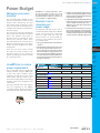
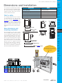
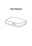
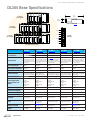
Prices as of April 16, 2014. Check Web site for most current prices.
DL305 Base Specifications
1.6’
0.5 M
5-slot I/O base
(local or expansion)
1.115”
29.9mm
I/O Expansion Cable (D3-EXCBL)
8-slot I/O base
(local or expansion)
94--240V
RUN
10-slot I/O base
(local or expansion)
94-240 VAC
Terminal Strip
24V OUT
LG
G
(Bases provide built-in power supplies)
D3-05B-1 <--->
D3-05BDC <--->
D3-08B-1 <--->
D3-10B-1 <--->
D3-10BDC <--->
Number of Slots
5
Local CPU Base
Yes
Yes
Yes
Yes
Yes
Expansion Base
Yes
CPU base and two expansion
bases. If CPU base is 5-slot,
then the expansion bases must
be 5-slot also.
Yes
CPU base and two expansion
bases. If CPU base is 5-slot,
then the expansion bases must
be 5-slot also.
Yes (D3-350 only)
CPU base and two expansion
bases. If CPU base is 8-slot,
then the expansion bases must
be 8-slot or 5-slot
Yes
CPU base and one expansion
bases. If CPU base is 10-slot,
then the expansion bases must
be 10-slot or 5-slot
Yes
CPU base and one expansion
bases. If CPU base is 10-slot,
then the expansion bases must
be 10-slot or 5-slot.
Input Voltage Range
85-264VAC
47-63Hz
20.5-30VDC
<10% ripple
85-264VAC
47-63Hz
85-264VAC
47-63Hz
20.5-30VDC
<10% ripple
5
8
10
10
Base Power Consumption 85 VA Max
48 Watts
85VA Max
85VA Max
65 Watts
Inrush Current Max.
30A 1ms
30A
30A 1ms
30A 1ms
30A
Dielectric Strength
1500VAC for one minute
1500VAC for one minute
between terminals of AC P/S, between 24VDC input
run output, common, 24VDC terminals and run output
Insulation Resistance
>10Mohm at 500VDC
>10Mohm at 500VDC
>10Mohm at 500VDC
>10Mohm at 500VDC
>10Mohm at 500VDC
Power Supply Output
(Voltage Ranges and
Ripple)
(5VDC) 4.75-5.25V
5% ripple
(9VDC) 8.5-10V
5% ripple
(24VDC) 20-28V
5% ripple
(5VDC) 4.75-5.25V
5% ripple
(9VDC) 8.5-10V
5% ripple
(24VDC) 20-28V
5% ripple
(5VDC) 4.75-5.25V
5% ripple
(9VDC) 8.5-10V
5% ripple
(24VDC) 20-28V
5% ripple
(5VDC) 4.75-5.25V
5% ripple
(9VDC) 8.5-10V
5% ripple
(24VDC) 20-28V
5% ripple
(5VDC) 4.75-5.25V
5% ripple
(9VDC) 8.5-10V
5% ripple
(24VDC) 20-28V
5% ripple
5 VDC Current Supplied
.7A
1.4A
1.0A
1.0A
1.4A
9 VDC Current Supplied
2.0A
0.8A
2.0A
2.0A
1.7A
24 VDC Current Supplied
0.5A
0.5A
0.5A
0.5A
0.5A
Auxiliary 24 VDC Output
100mA max
None
100mA max
100mA max
None
Run Relay
250VAC
4A (resistive load)
250VAC
4A (resistive load)
250VAC
4A (resistive load)
250VAC
4A (resistive load)
250VAC,
4A (resistive load)
Fuses
2A (250V) Non-replaceable
4A (250V)
User-replaceable
D3-FUSE-3 <--->
2A (250V) Non-replaceable
2A (250V) Non-replaceable
4A (250V)
User-replaceable
D3-FUSE-3 <--->
Dimensions W/H/D
11.42x4.85x4.41 in.
(290x123x112 mm)
11.42x4.85x4.41 in.
(290x123x112 mm
15.55x4.85x4.41 in.
(395x123x112 mm)
18.3x4.85x4.41 in.
(465x123x112 mm)
18.34x4.85x4.41 in.
(465x123x112 mm)
Weight
37oz. (1050g)
34oz. (964g)
44oz. (1250g)
51.1oz. (1450g)
50.5oz. (1432g)
1500VAC for one minute
2000VAC for one minute
1500VAC for one minute
between terminals of AC P/S, between terminals of AC P/S, between 24VDC input terminals
run output, common, 24VDC run output, common, 24VDC and run output
Book 1 (14.1)
eD3-22
DL305 PLCs
1-800-633-0405
Prices as of April 16, 2014. Check Web site for most current prices.
Power Budget
Managing your power
resource
The I/O configuration depends on your
choice of I/O modules, bases and I/O
location. When determining the types
and quantity of I/O modules you will be
using, it’s important to remember there is
a limited amount of power available from
the power supply.
The chart on the next page indicates the
power supplied and used by each DL305
device. The adjacent chart shows an
example of how to calculate the power
used by your particular system. These
two charts should make it easy for you to
determine if the devices you have chosen
fit within the power budget of your system
configuration.
If the I/O you have chosen exceeds
the maximum power available from
the power supply, you can resolve the
problem by shifting some of the modules
to an expansion base.
Use ZIPLinks to reduce
power requirements
If your application requires a lot of relay
outputs, consider using the ZIPLink AC
or DC relay output modules. These
modules can switch high current (10A)
loads without putting a load on your
base power budget. Refer to the Wiring
Solutions section in this catalog for more
information.
This logo is placed next to I/O modules
that are supported by the ZIPLink
connection systems. See the I/O module
specifications at the end of this section.
Company
Information
WARNING: It is extremely important to calculate the power budget correctly. If you exceed
the power budget, the system may operate in an
unpredictable manner, which may result in a risk
of personal injury or equipment damage.
3. Addthecurrentusedbythesystemdevices
(columns3,4,and5),startingwithSlot1,then
put the total in the row labeled “Maximum
Current Required” (Row E).
4. Subtracttherowlabeled“MaximumCurrent
Required” (Row E), from the row labeled
“Current Supplied” (Row B). Place the
difference in the row labeled “Remaining
Current” (Row F).
5. If “Maximum Current Required” is greater
than“CurrentSupplied”incolumns3,4or5,
thepowerbudgetwillbeexceeded.Itwillbe
unsafetousethisconfigurationandyouwill
need to restructure your I/O configuration.
Example: how to
calculate your
power usage
The following example shows how to
calculate the power budget for the DL305
system. The examples are constructed
around a single 5-slot base using the
devices shown. It is recommended you
construct a similar table for each base in
your DL305 system.
1. Using a chart similar to the one below, fill in
column 2.
2. Usingthetablesontheoppositepage,enter
the current supplied and used by each
device (columns 3, 4, and 5). Devices which
fall into the “Other” category (Row D) are
devicessuchastheHandheldProgrammer
or a Data Communication Unit, which also
havepowerrequirements,butdonotdirectly plug into the base.
Control Systems
Overview
CLICK PLC
Do-More
PLCs Overview
Do-More H2
PLC
Do-More T1H
PLC
DirectLOGIC
PLCs Overview
DirectLOGIC
DL05/06
DirectLOGIC
DL105
DirectLOGIC
DL205
DirectLOGIC
DL305
DirectLOGIC
DL405
Productivity
Controller
Overview
Productivity
3000
A
Column 1
Base # 0
Column 2
Device Type
Column 3
5 VDC (mA)
Column 4
9VDC (mA)
Column 5
24V(mA)
B Current Supplied
5-slot Base
D3-05BDC
Software
1400
800
500
C Current Required
CPU Slot
D3-330
300
50
0
Slot 0
D3-16NE3
0
130
0
Slot 1
D3-16NE3
0
130
0
Slot 2
D3-08TA-1
0
160
0
Slot 3
D3-08TA-1
0
160
0
50
50
0
360
680
0
1040
120
500
E Maximum Current Required
F Remaining Current
ViewMarq
Industrial
Marquees
Other HMI
Communications
Appendix
Book 1
Book 1 (14.1)
www.automationdirect.com/dl305
C-More
HMI
C-More Micro
HMI
D Other
Handheld prog D3-HPP
Universal
Field I/O
DL305 PLCs
eD3-23
Terms and
Conditions
Prices as of April 16, 2014. Check Web site for most current prices.
DL305 Power Requirements
This section shows the amount
of power supplied by the base
power supplies and the amount
of power used by each DL305
device. Note the base power
supplies provide three internal
voltages (5V, 9V, 24V). The chart
shows how much power from
each of these power sources is
required for each DL305 device.
Use this information when
calculating the power budget for
your system.
In addition to the three internal
power sources, the DL305
bases provide an external power
connection. There is 24 VDC
available from the 24 VDC output
terminals on the bases (except
D3-05BDC and D3-10BDC).
The 24 VDC can be used to
power external devices or DL305
modules that require external 24
VDC. The power used from this
external 24 VDC output reduces
the internal system 24 VDC that
is available to the modules by
an equal amount. When using
the 24 VDC output at the base
terminal, it is recommended that
100 mA not be exceeded.
Power Consumed
Device
Power Supplied
5V(mA) 9V(mA) 24V(mA) Ext
req.
CPUs
D3-330
D3-340
D3-350
300
300
500
50
20
0
0
0
0
0
0
0
DC Input Modules
D3-08ND2
D3-16ND2-1
D3-16ND2F
F3-16ND3F
0
0
0
0
10
25
25
148
112
224
224
68
0
0
0
0
10
10
100
0
0
0
0
0
0
0
0
0
0
Device
5V(mA) 9V(mA) 24V(mA) 24 V (mA)
D3-05B-1
D3-08B-1
D3-10B-1
D3-05BDC
D3-10BDC
D3-05B-NR
D3-08B-NR
900
900
900
900
900
900
900
2000
2000
2000
2000
2000
2000
2000
500
500
500
500
500
500
500
100
100
100
None
None
100
100
D3-05BDC-NR 900
2000
500
None
Power Consumed
Device
AC Input Modules
D3-08NA-1
D3-08NA-2
D3-16NA
0
0
0
AC/DC Input Modules
D3-08NE3
D3-16NE3
0
0
10
130
DC Output Modules
D3-04TD1
D3-08TD1
D3-08TD2
D3-16TD1-1
D3-16TD2
0
0
0
0
0
12
20
30
40
180
5
24
0
96
0
0
0
0
0
0
12
200
160
160
250
400
0
0
0
0
0
0
0
0
0
0
0
0
AC Output Modules
D3-04TAS
F3-08TAS-1
D3-08TA-1
D3-08TA-2
F3-16TA-2
D3-16TA-2
0
0
0
0
0
0
5V(mA) 9V(mA) 24V(mA) External
required
Relay Output Modules
D3-08TR
F3-08TRS-1
F3-08TRS-2
D3-16TR
0
0
0
0
360
296
296
480
0
0
0
0
0
0
0
0
Analog Temperature and Thermocouple Modules
F3-04ADS
F3-08AD-1
F3-08THM-n
F3-16AD
F3-04DA-1
F3-04DAS
0
0
0
0
0
0
183
45
50
55
144
154
50
55
34
65
108
145
0
0
0
0
0
0
Communications and Networking
D3-232 DCU
D3-422 DCU
FA-UNICON
D3- DCM
500
500
0
0
0
0
0
300
0
0
0
0
Optional 5V@500mA
Optional 5V@500mA
24V or 5V@ 100mA
0
10
70
5
112
0
0
0
0
0
50
50
0
0
0
0
0
0
0
0
0
0
0
0
150
0
0
0
0
0
0
0
0
0
0
0
0
Specialty Modules
D3-08SIM
D3-HSC
D3-TCSU
0
0
40
Programming
D3-HP
D3-HPP
D2-HP
50
50
200
Specialty CPUs
F3-OMUX-1
F3-OMUX-2
F3-PMUX
F3-RTU
409
262
455
416
Operator Interface
150
DV-1000
210
C-more
Micro-Graphic
Book 1 (14.1)
eD3-24
DL305 PLCs
1-800-633-0405
Prices as of April 16, 2014. Check Web site for most current prices.
Dimensions and Installation
It is important to understand the installation requirements for your DL305 system.
This will help ensure that the DL305
products operate within their environmental and electrical limits.
Plan for safety
This catalog should never be used as
a replacement for the user manual.
The user manuals, D3-USER-M and
D3-350-M (available for download from
our web site), contain important safety
information that must be followed. The
system installation should comply with
all appropriate electrical codes and standards.
Company
Information
Specification
Control Systems
Overview
Rating
Storage Temperature
Ambient Operating Temperature
Ambient Humidity
Vibration Resistance
Shock Resistance
-4°F - 158°F (-20°C to 70°C)
Noise Immunity
NEMA (ICS3-304)
CLICK PLC
32°F - 131°F (0° to 55°C)
30% - 95% relative humidity (non-condensing)
MIL STD 810C, Method 514.2
Do-More
PLCs Overview
Do-More H2
PLC
MIL STD810, Method 516.2
Do-More T1H
PLC
DL305 mounting depths
DirectLOGIC
PLCs Overview
OK
DirectLOGIC
DL05/06
DirectLOGIC
DL105
4.41”
112mm
Base dimensions and
mounting orientation
5”
127mm
Use the diagrams to the right to make
sure the DL305 system can be installed
in your application. DL305 bases must
be mounted horizontally to ensure proper
airflow for cooling purposes. It is important to check these dimensions against
the conditions required for your application. For example, it is recommended
that you leave 1.5” depth for ease of
access and cable clearance. However,
your distance may be greater or less.
Also, check the installation guidelines for
the recommended cabinet clearances.
Base and CPU
DirectLOGIC
DL205
Airflow
With 8-pt., 16-pt. I/O, or
handheld
DirectLOGIC
DL305
DirectLOGIC
DL405
Productivity
Controller
Overview
Productivity
3000
5.94”
151mm
Base and CPU with DCU, or
Thumbwheel interface
6.75”
171mm
Universal
Field I/O
With PROM Writer Unit (-lines)
9.0”
229mm
Software
With DCU and D3-DSCBL-2 connected
See the
Enclosures section in
this catalog for an enclosure
that may be suitable for your
application
C-More
HMI
C-More Micro
HMI
ViewMarq
Industrial
Marquees
Other HMI
Communications
Terms and
Conditions
C
Base
2"
50mm
min
D
Price
A
Appendix
Book 1
2"
50mm
min
A
B
B
C
2"
50mm
min
D
D3-05B-1 <--->
11.41” 290mm 10.63” 270mm 4.84” 123mm 3.54”
90mm
D3-08B-1 <--->
15.55” 395mm 14.76” 375mm 4.84” 123mm 3.54”
90mm
D3-10B-1 <--->
18.30” 465mm 17.51” 445mm 4.84” 123mm 3.54”
90mm
P anel
Component
Chas s is
Ground Braid
Copper Lugs
P anel or
S tar Was hers
S tar Was hers
Ground
Book 1 (14.1)
www.automationdirect.com/dl305
DL305 PLCs
eD3-25