1
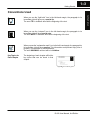
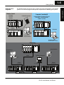
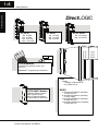
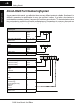
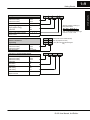
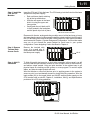
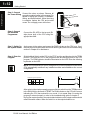
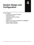
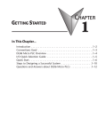
Getting Started
11
In This Chapter. . . .
— Introduction
— DL305 System Components
— Programming Methods
— DirectLOGIC™ Part Numbering System
— Quick Start for PLC Validation and Programming
— Steps to Designing a Successful System
1--2
Getting Started
Getting Started
Introduction
The Purpose of
this Manual
Thank you for purchasing our DL305
family of products. This manual shows you
how to install, program, and maintain the
equipment. It also helps you understand
how to interface them to other devices in a
control system.
This
manual
contains
important
information for personnel who will install
DL305 PLCs, DL350 CPU and
components,
and
for
the
PLC
programmer. If you understand PLC
systems, our manuals will provide all the
information you need to start and keep
your system up and running.
Where to Begin
If you already understand PLCs please read Chapter 2, “Installation, Wiring, and
Specifications”, and proceed on to other chapters as needed. Keep this manual
handy for reference when you have questions. If you are a new DL305 customer, we
suggest you read this manual completely to understand the wide variety of features
in the DL305 family of products. We believe you will be pleasantly surprised with how
much you can accomplish with AutomationDirect™ products.
Supplemental
Manuals
If you have purchased operator interfaces or DirectSOFT™, you will need to
supplement this manual with the manuals that are written for these products.
Technical Support
We realize that even though we strive to be the best, we may have arranged our
information in such a way you cannot find what you are looking for. First, check these
resources for help in locating the information:
S
S
S
Table of Contents -- chapter and section listing of contents, in the front
of this manual
Appendices -- reference material for key topics, near the end of this
manual
Index -- alphabetical listing of key words, at the end of this manual
You can also check our online resources for the latest product support information:
S Internet -- Our Web address is
http://www.automationdirect.com
If you still need assistance, please call us at 770--844--4200. Our technical support
group is glad to work with you in answering your questions. They are available
Monday through Friday from 9:00 A.M. to 6:00 P.M. Eastern Standard Time. If you
have a comment or question about any of our products, services, or manuals, please
fill out and return the ‘Suggestions’ card that was shipped with this manual.
DL350 User Manual, 2nd Edition
Getting Started
1--3
Conventions Used
When you see the “notepad” icon in the left--hand margin, the paragraph to its
immediate right will be a special note.
The word NOTE: in boldface will mark the beginning of the text.
When you see the “exclamation mark” icon in the left--hand margin, the paragraph to
its immediate right will be a warning. This information could prevent injury, loss of
property, or even death (in extreme cases).
The word WARNING: and text will be in boldface.
Key Topics for
Each Chapter
The beginning of each chapter will list the
key topics that can be found in that
chapter.
1
DL350 User Manual, 2nd Edition
Getting Started
When you see the “light bulb” icon in the left--hand margin, the paragraph to its
immediate right will give you a special tip.
The word TIP: in boldface will mark the beginning of the text.
1--4
Getting Started
Getting Started
DL305 System Components
The DL305 family is a versatile product line that provides a wide variety of features in
an extremely compact package. The CPUs are small, but offer many instructions
normally only found in larger, more expensive systems. The modular design also
offers more flexibility in the fast moving industry of control systems. The following is a
summary of the major DL305 system components.
There are three feature enhanced CPUs in this product line, the DL330, DL340, and
the DL350. This manual covers the DL350 CPU only. The DL330 and DL340 CPUs
are covered in detail in the DL305C User Manual. The DL350 CPU includes built-in
communication ports, a large amount of program memory, a substantial instruction
set and advanced diagnostics. It also features drum timers, floating--point math, and
built in PID loops with automatic tuning.
CPUs
Bases
Three base sizes are available: 5 slot, 8 slot, and 10 slot. One slot is for the CPU, the
remaining slots are for I/O modules. All bases include a built-in power supply.
Currently there are two versions of the bases. The xxxxx--1 bases were designed to
compliment the DL350 CPU. Any of the three CPUs will work in either type of base
and the bases can be mixed in a system. When the DL350 CPU is used in an old
base, or if it is in a system of mixed bases, it will act similar to the DL340 CPU in
addressing and I/O configuration (See Appendix F).
I/O Configuration
The DL350 CPU can support up to 368 I/O points with the bases currently available.
These points can be assigned as input or output points. The DL305 system can also
be expanded by adding remote I/O. The DL350 also provides a built--in master for
remote I/O networks. The I/O configuration is explained in Chapter 4, System
Design and Configuration.
I/O Modules
The DL305 has some of the most powerful modules in the industry. A complete
range of discrete modules which support 24 VDC, 110/220 VAC and up to 10A relay
outputs are offered. The analog modules provide 12 bit resolution and several
selections of input and output signal ranges (including bipolar).
Programming Methods
There are two programming methods available to the DL350 CPU, RLL (Relay
Ladder Logic) and RLL PLUS (Stage Programming). Both the DirectSOFT™
programming package and the handheld programmer support RLL and Stage.
DirectSOFT
Programming for
Windows™
The DL305 can be programmed with one of the most advanced programming
packages in the industry ----DirectSOFT. DirectSOFT is a Windows-based software
package that supports many Windows-features you are already know, such as cut
and paste between applications, point and click editing, viewing and editing multiple
application programs at the same time, etc. DirectSOFT universally supports the
DirectLOGIC™ CPU families. This means you can use the same DirectSOFT
package to program DL105, DL205, DL305, DL405 or any new CPUs we may add to
our product line. There is a separate manual that discusses the DirectSOFT
programming software.
Handheld
Programmer
The DL350 CPU has a built-in programming port for use with the DL205 handheld
programmer (D2--HPP). The handheld programmer can be used to create, modify
and debug your application program. A separate manual that discusses the
Handheld Programmer is available.
DL350 User Manual, 2nd Edition
1--5
Getting Started
The diagram below shows the major components and configurations of the DL305
system. The next two pages show specific components for building your system.
Machine Control
Computer Controlled I/O
Packaging
Conveyors
Elevators
Handheld Programmer
Industry Standard Computer I/O Protocol
OPTOMUX™ (Serial RS422/485)
PAMUX™ (Parallel)
DL305
DL305
1.5ft
(.05m)
1.5ft
(.05m)
RS232C
(max.50ft/16.2m)
RS422/485
DL305
DL305
Programming or
Computer Interface
Computer Interface
with OPTOMUX™ Driver
Networking
DL305
Operator Interface
Programming or
Computer
Interface
Handheld Programmer
RS422
RS232C
(max.50ft/16.2m)
DL305
RS232C/422
Convertor
(max. 4.6ft / 1.5m)
DL305
RS232C/422
Convertor
RS232C
(max.50ft/16.2m)
DL305
RS232C/422
Convertor
DL350 User Manual, 2nd Edition
Getting Started
DL305 System
Diagrams
Getting Started
DirectLOGIC
Getting Started
1--6
DC INPUT
8pt
16pt
16pt
16pt
24 VDC
24 VDC
5-24 VDC
12-24 VDC
AC INPUT
AC/DC INPUT
8pt 110 VAC
16pt 110 VAC
8pt 220 VAC
8pt 24 VAC/DC
16pt 24 VAC/DC
PROGRAMMING
Handheld Programmer for RLL and
RLL PLUS
DirectSOFT Programming for Windows™
CPUs
DL350
7.6K Built in Flash memory
and 2 Built-in Ports
ASCII BASIC Modules
RS232C / RS422 / RS485
Built-in Radio Modem
Built-in Telephone Modem
Program Memory 64K/128K
DL350 User Manual, 2nd Edition
BASES
5 Slot Base w/Expansion Capability,
110/220 VAC P/S
5 Slot Base w/Expansion Capability,
24 VDC Supply
8 Slot Base w/Expansion Capability,
110/220 VAC P/S
10 Slot Base w/Expansion Capability,
110/220 VAC P/S
Getting Started
DC OUTPUT
8pt 5--24 VDC
16pt 5--24 VDC
Getting Started
DL305 Family
RELAY OUTPUT
AC OUTPUT
4 pt
8pt
8pt
16pt
16pt
8pt
8pt
8pt
16pt
110--220 VAC
110--220 VAC
12--220 VAC
12--220VAC
15--220VAC
4A/pt AC
5A/pt DC
10A/pt
2A/pt
ANALOG
4ch
8ch
16ch
2ch
4ch
8ch
INPUT
INPUT
INPUT
OUTPUT
OUTPUT
TEMPERATURE
TRANSDUCER INPUT
8ch THERMOCOUPLE
INPUT
SPECIALTY CPUs
Bridge CPU to connect
to host w/OPTOMUX™ Driver
Bridge CPU w/FACTS
Extended Basic Programming
Bridge CPU to connect to
High-speed PAMUX™
compatible host
SPECIALTY
MODULES / UNITS
1--7
NETWORKING
RS232C Data Communication Unit
RS422 Data Communication Unit
MODBUS® Slave Module
MODBUS® Slave Module
w/Radio Modem
Universal connector:
RS232C / RS422/485 Convertor
8pt INPUT Simulator
1pt High Speed Counter
PROM Writer Unit
Filler Module
DL350 User Manual, 2nd Edition
1--8
Getting Started
Getting Started
DirectLOGIC Part Numbering System
As you examine this manual, you will notice there are many different products available. Sometimes it is
difficult to remember the specifications for any given product. However, if you take a few minutes to
understand the numbering system, it may save you some time and confusion. The charts below show how
the part numbering systems work for each product category. Part numbers for accessory items such as
cables, batteries, memory cartridges, etc. are typically an abbreviation of the description for the item.
CPUs
Specialty CPUs
Product family
D1/F1
D4--
440DC
--1
D2/F2
D3/F3
D4/F4
Class of CPU / Abbreviation
230...,330...,430...
Denotes a differentiation between
Similar modules
--1, --2, --3, --4
Bases
Product family
D3--
05B
DC
D4--
16
N
D
2
D3--
16
N
D
2
D2/F2
D3/F3
D4/F4
Number of slots
##B
Type of Base
DC or empty
Discrete I/O
DL205 Product family
y
D2/F2
/
DL305 Product family
y
D3/F3
DL405 Product family
D4/F4
Number of points
04/08/12/16/32
Input
p
N
Output
p
T
Combination
C
AC
A
DC
D
Either
E
Relay
Current Sinking
g
R
1
Current Sourcing
g
2
Current Sinking/Sourcing
3
High
g Current
H
Isolation
S
Fast I/O
Denotes a differentiation between
Similar modules
F
--1, --2, --3, --4
DL350 User Manual, 2nd Edition
F
--1
1--9
Getting Started
F3--
DL205 Product family
y
D2/F2
/
DL305 Product family
y
D3/F3
DL405 Product family
D4/F4
Number of channels
02/04/08/16
Input
p ((Analog
g to Digital)
g )
AD
Output
p ((Digital
g
to Analog)
g)
DA
Combination
Isolated
AND
S
Denotes a differentiation between
Similar modules
--1, --2, --3, --4
Communication and Networking
Special I/O and Devices
Programming
DL205 Product family
D2/F2
DL305 Product family
D3/F3
DL405 Product family
D4/F4
Name Abbreviation
see example
CoProcessors and ASCII BASIC Modules
DL205 Product family
y
D2/F2
/
DL305 Product family
y
D3/F3
DL405 Product family
D4/F4
CoProcessor
CP
ASCII BASIC
AB
64K memoryy
64
128K memoryy
128
512K memory
512
Radio modem
R
Telephone modem
T
04
AD
S
--1
Alternate example of Analog I/O
using
abbreviations
o
F3--
08
THM
--n
note: --n indicates thermocouple type
such as: J, K, T, R, S or E
D4--
DCM
DCM (Data Communication Module)
D3--
HSC
HSC (High Speed Counter)
D3--
HPP
F4--
CP
HPP (RLL PLUS Handheld Programmer)
128
-- R
DL350 User Manual, 2nd Edition
Getting Started
Analog I/O
1--10
Getting Started
Getting Started
Quick Start for PLC Validation and Programming
If you have experience with PLCs, or want to setup a quick example, this section is
what you want to use. This example is not intended to explain everything needed to
start-up your system. It is only intended to provide a general picture of what is
needed to get your system powered-up.
Step 1: Unpack the Unpack the DL305 equipment and verify you have the parts necessary to build this
demonstration system. The minimum parts needed are as follows:
DL305
Equipment
S Base
S CPU
S D3--08ND2 DC input module or a D3--08SIM input simulator module
S D3--08TD2 DC output module
S *Power cord
S *Hook up wire
S *A 24 VDC toggle switch (if not using the input simulator module)
S *A screwdriver, regular or Phillips type
* These items are not supplied with your PLC.
You will need at least one of the following programming options:
S DirectSOFT Programming Software, DirectSOFT Manual, and a
programming cable (connects the CPU to a personal computer), or
S D2--HPP Handheld Programmer and the Handheld Programmer Manual
DL350 User Manual, 2nd Edition
1--11
Getting Started
Insert the CPU and I/O into the base. The CPU must go into the first slot of the base
(adjacent to the power supply).
S Each unit has a plastic retaining
clip at the top and bottom.
S With the unit square to the base,
slide it in using the upper and
lower guides.
S Gently push the unit back until it
is firmly seated in the backplane
and the plastic clips lock in place.
CPU must reside in first slot!
Placement of discrete, analog and relay modules are not critical and may go in any
slot in any base however for this example install the output module in the slot next to
the CPU and the input module in the next. Limiting factors for other types of modules
are discussed in Chapter 4, System Design and Configuration. You must also make
sure you do not exceed the power budget for each base in your system
configuration. Power budgeting is also discussed in Chapter 4.
Step 3: Remove
Terminal Strip
Access Cover
Remove the terminal strip
cover. It is a small strip of
clear plastic that is located on
the base power supply.
Step 4: Add I/O
Simulation
To finish this quick start exercise or study other examples in this manual, you will
need to install an input simulator module (or wire an input switch as shown below),
and add an output module. Using an input simulator is the quickest way to get
physical inputs for checking out the system or a new program. To monitor output
status, any discrete output module will work.
Wire the switches or other field devices prior to applying power to the system to
ensure a point is not accidentally turned on during the wiring operation. Wire the
input module (X0) to the toggle switch and 24VDC auxiliary power supply on the
CPU terminal strip as shown. Chapter 2, Installation, Wiring, and Specifications
provides a list of I/O wiring guidelines.
Lift off
Toggle switch
DL350 User Manual, 2nd Edition
Getting Started
Step 2: Install the
CPU and I/O
Modules
Getting Started
1--12
Getting Started
Step 5: Connect Connect the wires as shown. Observe all
the Power Wiring precautions stated earlier in this manual. For
details on wiring see Chapter 2, Installation,
Wiring, and Specifications. When the wiring
is complete, replace the CPU and module
covers. Do not apply power at this time.
Line
Neutral
Ground
Step 6: Connect
the Handheld
Programmer
Connect the D2--HPP to the top port (RJ
style phone jack) of the CPU using the
appropriate cable.
Step 7: Switch On
the System Power
Apply power to the system and ensure the PWR indicator on the CPU is on. If not,
remove power from the system and check all wiring and refer to the troubleshooting
section in Chapter 9 for assistance.
Step 8: Enter the
Program
Slide the Mode Switch on the CPU to the STOP position and then back to the TERM
position. This puts the CPU in the program mode and allows access to the CPU
program. The PGM indicator should be illuminated on the HPP. Enter the following
keystrokes on the HPP:
NOTE: It is not necessary for you to configure the I/O for this system since the DL350
CPU automatically examines any installed modules and establishes the correct
configuration.
Handheld Programmer Keystrokes
$
STR
GX
OUT
B
C
1
2
X1
Y0
OUT
ENT
ENT
NOP
After entering the simple example program slide the switch from the TERM position
to the RUN position and back to TERM. The RUN indicator on the CPU will come on
indicating the CPU has entered the run mode. If not repeat Step 8 insuring the
program is entered properly or refer to the troubleshooting guide in chapter 9.
During Run mode operation, the output status indicator on the output module should
reflect the switch status. When the switch is on the output should be on.
DL350 User Manual, 2nd Edition
Getting Started
1--13
Steps to Designing a Successful System
Always make safety your first priority in
any system application. Chapter 2
provides several guidelines that will help
provide a safer, more reliable system.
This chapter also includes wiring
guidelines for the various system
components.
Step 2:
Understand the
CPU Setup
Procedures
The CPU is the heart of your automation
system. Make sure you take time to
understand the various features and
setup requirements.
Step 3:
Understand the
I/O System
Configurations
It is important to understand how your
local I/O system can be configured. It is
also important to understand how the
system Power Budget is calculated. This
can affect your I/O placement and/or
configuration options.
Step 4:
Determine the I/O
Module
Specifications
and Wiring
Characteristics
There are many different I/O modules
available with the DL305 system.
Chapter 2 provides the specifications
and wiring diagrams for the discrete I/O
modules.
Getting Started
Step 1:
Review the
Installation
Guidelines
Y40 X20 X10
to
to
to
Y57 X37 X17
NOTE: Specialty modules have their
own manuals and are not included in this
manual.
Step 5:
Understand the
System Operation
Before you begin to enter a program, it is
very helpful to understand how the
DL305 system processes information.
This involves not only program execution
steps, but also involves the various
modes of operation and memory layout
characteristics. See Chapter 3 for more
information.
Power up
Initialize hardware
Check I/O module
config. and verify
DL350 User Manual, 2nd Edition
Getting Started
1--14
Getting Started
Step 6:
Review the
Programming
Concepts
The DL305 provides four main approaches to solving the application program,
including the PID loop task depicted in the next figure.
S RLL diagram-style programming is the best tool for solving boolean logic
and general CPU register/accumulator manipulation. It includes dozens
of instructions, which will augment drums, stages, and loops.
S The DL350 has four timer/event drum types, each with up to 16 steps.
They offer both time and/or event-based step transitions. Drums are
best for a repetitive process based on a single series of steps.
S Stage programming (also called RLL Plus) is based on state-transition
diagrams. Stages divide the ladder program into sections which
correspond to the states in a flow chart of your process.
S The DL350 PID Loop Operation uses setup tables to configure 4 loops.
Features include; auto tuning, alarms, SP ramp/soak generation, and
more.
Timer/Event Drum Sequencer
(see Chapter 6)
Standard RLL Programming
(see Chapter 5)
X0
LDD
V1076
CMPD
K309482
SP62
Y0
OUT
Stage Programming
(see Chapter 7)
Push--UP
PID Loop Operation
(see Chapter 8)
RAISE
SP
DOWN
LIGHT
UP
+
Σ
PID
Process
-PV
LOWER
Push-DOWN
Step 7:
Choose the
Instructions
Once you have installed the system and
understand the theory of operation, you
can choose from one of the most
powerful instruction sets available.
Step 8:
Understand the
Maintenance and
Troubleshooting
Procedures
Equipment failures can occur at any time.
Switches fail, batteries need to be
replaced, etc. In most cases, the majority
of the troubleshooting and maintenance
time is spent trying to locate the problem.
The DL305 system has many built-in
features that help you quickly identify
problems. Refer to Chapter 9 for
diagnostics and troubleshooting tips.
DL350 User Manual, 2nd Edition
TMR
K30
T1
CNT CT3
K10