1
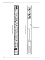
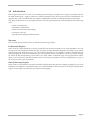
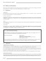
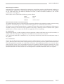
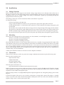
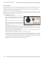
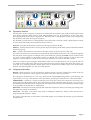
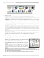
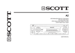
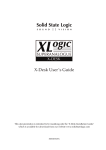
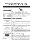
Super Analogue Channel
Owner’s Manual
Solid State Logic
SUPER ANALOGUE
CHANNEL
Super-Analogue™ Outboard
Owner’s Manual
82S6XL040D
XLogic Channel Owner’s Manual
Solid State Logic
Begbroke, Oxford, England, OX5 1RU • +44 (0)1865 842300
320 West 46th Street, 2nd Floor, New York, NY 10036, USA • +1 (1) 212 315 1111
Suite 401, 5757 Wilshire Blvd, Los Angeles, CA 90036, USA • +1 (1) 323 549 9090
3-55-14 Sendagaya, Shibuya-Ku, Tokyo 151-0051, Japan • +81 (0)3 5474 1144
7 bis, rue de la Victoire, le Blanc Mesnil, Paris 93150, France • +33 (0)1 48 67 84 85
Via Timavo 34, 20124 Milano, Italy • +39 (0)39 2328 094
Visit SSL at URL: http://www.solid-state-logic.com
© Solid State Logic
All Rights reserved under International and Pan-American Copyright Conventions
Solid State Logic, SSL and XLogic are trademarks of Solid State Logic
All other product names and trademarks are the property of their respective owners
No part of this publication may be reproduced in any form or
by any means, whether mechanical or electronic, without the
written permission of Solid State Logic, Oxford, England
Revision 0A, September 2003
Revision 0B, January 2004
Revision 0C, June 2004
Revision 0D, July 2004
Minor changes, November 2004
Minor changes, June 2005
As research and development is a continual process, Solid State Logic reserves the right
to change the features and specifications described herein without notice or obligation
E&OE
Contents
1.0 Introduction
3
2.0 Safety Considerations
Safety Warnings
4
4
3.0 Installation
Setting the mains voltage selector
Mounting
Connections
7
7
7
7
4.0 Operation
Input Section
Dynamics Section
Filter Section
Equaliser Section
Output Section
8
8
9
10
11
11
5.0 Signal Routing
Block Diagram
Signal Routing
12
12
13
Appendices:
A Internal Links and Fuses
B Connector Details
C Electronic Specification
D Calibration Information
E Physical Specification
F Environmental Specification
14
15
16
21
24
24
Page 1
Solid
State
Logic
Page 2
INPUT B - INSTRUMENT
6
HI Z
dB
72
54
60
PAD
66
18
12
24
INPUT GAIN
36 42
48
30
48V
INP
B
Ø
INST
KEY
DYN
IN
+10
0
PK
-20
FAST
ATT
THRESHOLD
1
COMPRESSOR
100V
120V
230V
240V
LINK
PRE
EQ
DYNAMICS
4
1
RELEASE
6
∞
1
10 14 20
RATIO
3
4
+10
0
0
EXP
THRESHOLD
0
40
RANGE
HPF
IN
30
4
20
60
HOLD
Hz
25
35
15
500
S/C
3
9
INPUT
KHz
300 DYN
100
LPF
IN
FILTERS
4
6
0
Hz
BELL
40
15
0
LF
XLogic Channel (rear)
FAST
ATT
RELEASE
30
GATE
XLogic Channel (front)
600
400
220
GAIN
+
Q
LMF
GAIN
.3
+
.2
.6
KHz
2.0
1.0
EQ
IN
1.6
E
DYN
S/C
HMF
Q
1
+
OUTPUT
GAIN
.6
2
KHz
7
3
HF
5
2
5
1.5
+
KEY IN
GAIN
KHz
22
10
BELL
15
DYN
LINK
-24 -12
MTR
INPUT
0
OUTPUT
+20
INPUT A
6 12 18 24
POWER
ADC LOCK
-20
GAIN
XL ogic
SUPER ANALOGUE
CHANNEL
XLogic Channel Owner’s Manual
Blanking plate for
(optional) ADC card
Introduction
1.0 Introduction
The XLogic Channel unit is a 1U rack mounting unit containing a complete set of signal processing from the
XL 9000 channel strip – Input, Compressor/Limiter, Expander/Gate, Hi and Lo pass filters and Equaliser. An
optional ADC card is available (SSL part number: 629945XT) to provide an additional digital audio output.
The object of this manual is to provide purchasers of the XLogic Channel unit with information in the following
areas:
• Safety considerations
• Installation requirement
• Electrical connections and cabling
• Connector pin outs
• Specifications and physical dimensions
Warranty
The warranty period for this unit is 12 months from date of purchase.
In Warranty Repairs
In the event of a fault during the warranty period the unit must be returned to your local distributor who will
arrange for it to be shipped to Solid State Logic for repair. All units should be shipped to Solid State Logic in their
original packaging. Solid State Logic can not be held responsible for any damage caused by shipping units in
other packaging. In such cases Solid State Logic will return the unit in a suitable box, which you will be charged
for. Please do not send manuals, power leads or any other cables - Solid State Logic can not guarantee to return
them to you. Please also note that warranty returns will only be accepted as such if accompanied by a copy of
the receipt or other proof of purchase.
Out of Warranty Repairs
In the event of a fault after the warranty period has expired, return the unit in its original packaging to your local
distributor for shipment to Solid State Logic. You will be charged for the time spent on the repair (at Solid State
Logic's current repair rate) plus the cost of parts and shipping.
Page 3
XLogic Channel Owner’s Manual
2.0 Safety considerations
This section contains definitions and warnings, and practical information to ensure a safe working environment.
Please take time to read this section before undertaking any installation work.
2.1
Definitions
‘Maintenance’
All maintenance must be carried out by fully trained personnel. Note: it is advisable to observe suitable ESD
precautions when maintenance to any part is undertaken.
‘Non-User Adjustments’
Adjustments or alterations to the equipment may affect the performance such that safety and/or international
compliance standards may no longer be met. Any such adjustments must therefore only be carried out by fully
trained personnel.
‘Users’
This equipment is designed for use solely by engineers and competent operators skilled in the use of professional
audio equipment.
‘Environment’
This product is a Class A product intended to form an integrated component part of a professional audio
recording, mixing, dubbing, film, TV, radio broadcast or similar studio wherein it will perform to specification
providing that it is installed according to professional practice.
2.2
Electrical Safety Warning
When installing or servicing any item of Solid State Logic equipment with power applied, when cover
panels are removed, HAZARDOUS CONDITIONS CAN EXIST.
These hazards include:
High voltages
High energy stored in capacitors
High currents available from DC power busses
Hot component surfaces
Any metal jewellery (watches, bracelets, neck-chains and rings) that could inadvertently come into contact
with uninsulated parts should always be removed before reaching inside powered equipment.
2.3
Installation
Voltage Selection and Fusing
All XLogic units have selectable voltage inlets. Always confirm that the input mains voltage range is set correctly
before applying power. Always isolate the mains supply before changing the input range setting.
If it is ever necessary to replace a blown mains-fuse, then always use the correct rating and type of replacement.
If a correctly rated fuse continues to blow, then a fault exists and the cause should be investigated or the unit
returned to Solid State Logic for repair/replacement as appropriate.
Details of mains settings and correct fuse ratings can be found in Section 3.1 and Appendix A of this manual.
Safety Earth Connection
Any mains powered item of Solid State Logic equipment that is supplied with a 3-core mains lead (whether
connectorised or not) should always have the earth wire connected to the mains supply ground. This is the safety
earth and grounds the exposed metal parts of the racks and cases and should not be removed for any reason.
Page 4
Safety Considerations
Mains Supply and Phases
Solid State Logic equipment is designed for connection to single phase supplies with the Neutral conductor at
earth potential – category TN – and is fitted with a protective fuse in the Live conductor only. It is not designed
for use with Phase (Live) and Neutral connections reversed or where the Neutral conductor is not at earth
potential (TT or IT supplies).
Mains cables will be coded with the following colour scheme:
LIVE:
Brown
NEUTRAL:
Blue
EARTH:
Yellow/Green
Mains Isolation and Over-Current Protection
An external disconnect device is required for this equipment which must be installed according to current wiring
regulations. A detachable power cord, as fitted to this equipment, is a suitable disconnect device.
An external over-current protection device is required to protect the wiring to this equipment which must be
installed according to the current wiring regulations. The fusing or breaking-current are defined in the product
specification. In certain countries this function is supplied by use of a fused plug.
CE Certification
Note that the majority of cables supplied with SSL equipment are fitted with ferrite rings at each end. This is to
comply with current European CE regulations and these ferrites should not be removed.
If any of the unit metalwork is modified in any way this may the adversely affect the CE certification status of
the product.
FCC Certification
The XLogic unit has been tested and found to comply with the limits for a Class A digital device, pursuant to
part 15 of the FCC Rules. These limits are designed to provide reasonable protection against harmful interference
when the equipment is operated in a commercial environment. This equipment generates, uses, and can radiate
radio frequency energy and, if not installed and used in accordance with the instruction manual, may cause
harmful interference to radio communications. Operation of this equipment in a residential area is likely to cause
harmful interference in which case the user will be required to correct the interference at his own expense.
Page 5
XLogic Channel Owner’s Manual
100V
120V
2 3 0V
2 4 0V
Mains Input Module
240
120
100
120V Setting
(Use for 105-125V)
100
240
230
230
100V Setting
(Use for 90-105V)
230
240
120
100
120
100
240
230V Setting
(Do not use)
240V Setting
(Use for 220-240V)
Mains Input Programming PCB
These diagrams show the PCB arrangements for the different voltage settings.
Note that where the mains voltage is a nominal 230V, the ‘240V Setting’ should be used – not the ‘230V Setting’!
Page 6
Installation
3.0 Installation
3.1
Voltage Selection
Before connecting the mains supply ensure that the voltage range selector next to the IEC socket on the rear of
the unit is correctly set. The input setting must be confirmed before applying power. The input module can be
configured to be one of 4 voltage settings. The setting is indicated by a plastic pin protruding through the
appropriate hole in the fuse panel.
The setting is altered by a small vertical PCB which can be fitted in 4 positions.
To change the setting:
Switch off and remove the IEC lead.
Using a small flat-bladed screwdriver, lever open the fuse panel to the right of the connector.
At the right hand side is a vertical PCB with a plastic key which indicates the setting. Using pliers, pull
out the PCB.
The PCB has to be rotated until the desired voltage is shown along the edge which plugs into the module.
The plastic key (and this bit is quite fiddly) must also be rotated so that it points out of the module and so
that the round pin aligns with the appropriate hole in the cover panel; (refer to the diagrams opposite).
Re-insert the PCB and replace the fuse panel. The plastic pin should project through the appropriate hole.
3.2
Mounting
The XLogic unit is designed to be rack-mounted. It is 1 RU (44.5mm/1.75 inch) high. Its depth is:
325 mm/12.8 inches not including heatsink.
365 mm/14.3 inches including heatsink
400 mm/15.75 inches including connectors
Please note that the rack ears of early XLogic Channel units are not capable of supporting the full weight of the
unit. Therefore if the unit is to be rack-mounted, it must either be mounted on suitable rack shelves or be fitted
with a pair of support brackets to reinforce the rack ears – do not rely on just the basic front panel for rack-mounting
the unit. Later XLogic Channel units incorporate reinforcement brackets into the chassis and so are suitable for
direct rack-mounting. Should your unit require them, pairs of support brackets (SSL Part No.: 629943XR) are
available from your local distributor.
A 1RU space should be left above each unit to ensure adequate ventilation.
3.3
Connection
There are four connectors on the rear panel and a single combined XLR and mono jack on the front panel.
The rear panel connections are:
Input A (female XLR)
Output (male XLR)
Key Input (female XLR)
Link Bus (TRS jack socket)
The front panel connections are:
Input B/Instrument (combined female XLR and mono jack)
Inputs A and B are can be used for either microphone or line level signals. The HI Z switch should be selected
when using line level signals as some devices may not be able to provide full output level in to the low (1.2kΩ)
impedance of the standard microphone input.
The mono jack provides a very high (1MΩ) impedance input, designed for use with guitar pickups, piezo electric
bugs etc.
Connect the output of the unit to your recorder, workstation or mixing desk. Connect the input to a suitable
source. If you have more than one unit the dynamics LINK jacks on the rear of the units should be connected
together using a mono or stereo jack–to–jack cable.
Page 7
XLogic Channel Owner’s Manual
4.0 Operation
The XLogic Channel unit is a 1U rack mounting unit containing a complete set of signal processing from the
XL 9000 channel strip – Input, Compressor/Limiter, Expander/Gate, Hi and Lo pass filters and Equaliser.
The signal processing order can be changed and the EQ and filter sections used in the dynamics side chain.
providing a wide range of signal processing options.
Obviously there are many different permutations of signal routing, allowing an enormous number of creative
possibilities. This section looks at each control on the XLogic Channel individually, with a brief summary of the
routing possibilities. See Section 5 for more on routing.
4.1
Channel Input Section
The channel input can pick up any one of three inputs:
INPUT GAIN
INP A With the INP B and INST switches released
the input is fed by the INPUT A XLR on the rear of the
unit.
36
48
24
54
18
INP B – Selects the female XLR on the front of the
unit.
INST – Selects the mono jack instrument input on the
front of the unit. This is a very high impedance
unbalanced input intended to be used with guitar
pickups etc.
42
30
INP
B
INST
48V
Ø
60
66
12
6
dB
HI Z
72
PAD
INPUT B - INSTRUMENT
The stepped INPUT GAIN control has a gain range of +6dB to +72dB in 6dB steps.
HI-Z – Increases the input impedance of the microphone input (inputs A or B) from 1.2kΩ to 8.45kΩ. This
allows the connection of line level signals to the channel input if required, and provides an alternative
input impedance for some dynamic microphones.
PAD – This switch reduces the signal level by 18dB. Setting the gain to +18dB and selecting PAD sets the
input gain to 0dB for use with line level signals.
48V – When selected provides phantom power to the associated microphone.
Please note that connecting a microphone to the XLogic Channel unit with phantom power switched on is not advised
as it may cause damage to either the microphone or the input stage of the XLogic Channel unit. Also note that
phantom power should be switched off before changing the input source to avoid possible damage to connected devices
or to the input stage of the XLogic Channel unit. Take care not to use phantom power when connecting line level
sources (keyboards etc.) as this may damage the output stage of the connected unit.
Ø (Phase) – This reverses the phase of the selected channel input.
Page 8
Operation
DYNAMICS
DYN
IN
COMPRESSOR
GATE
RELEASE
3
PRE
EQ
6
EXP
4
3
0
RELEASE
RATIO
THRESHOLD
0
FAST
ATT
LINK
+10
4.2
HOLD
0
10 14 20
PK
1
KEY
THRESHOLD
-20
+10
0
4
RANGE
FAST
ATT
1
∞
1
4
0
40
Dynamics Section
The Dynamics section comprises a compressor/limiter and an expander/gate, both of which use the same
gain change element. Both sections work independently, but can be operational at the same time,
providing sophisticated control of signal levels. The Filter and/or the Equaliser section can be assigned to
the dynamics side chain allowing de-essing etc.
The Dynamics section has two routing buttons associated with it. Section 5 deals with Dynamics routing
in more detail, but briefly these button function as follows:
DYN IN – Switches the Dynamics section into the signal path pre the EQ.
PRE EQ – Switches the Dynamics section pre the EQ section (but post the Filter section if the Filter INPUT
switch is pressed).
KEY – Switches the Dynamics side chain to the ‘KEY’ input on the rear panel of the unit.
If you have more than one unit and have connected the ‘DYN LINK’ jacks on the rear of the units together
the side chain control signals of multiple units can be linked by pressing the LINK switch on those units
you wish to gang. When two Dynamics sections are linked, the control voltages of each section sum
together, so that whichever section has the most gain reduction will control the other section.
Don’t try to link two gates using the LINK button when you want the signal on one to open the other. If
you need to achieve this effect, take a keying signal from one section to trigger the other. The easiest way
to do this is by patching from the output of the ‘source’ channel into the Key input of the ‘destination’
channel, and selecting KEY (see above) on this channel.
4.3
Compressor/Limiter
RATIO – When turned to 1:1, the Compressor/Limiter section is inactive. Turning the control clockwise
increases the compression ratio to give a true limiter at the fully clockwise position.
The compressor normally has an ‘over-easy’ characteristic. Selecting PK changes this to peak sensing, and
replaces the ’over–easy’ characteristic with a hard knee, providing an alternative for some instruments.
THRESHOLD – Whenever a signal exceeds the level set by this control, the compressor will start to act
at the ratio set by the RATIO control. This control also provides automatic make-up gain, so as you lower
the threshold and introduce more compression, the output level is increased, maintaining a steady output
level regardless of the amount of compression.
RELEASE – Sets the time constant (speed) with which the compressor returns to normal gain settings once
the signal has passed its maximum.
FAST ATT – Provides a fast attack time (3mS for 20dB gain reduction). When off the attack time is
program dependent (3mS – 30mS).
The yellow and red LEDs, on the bottom of the LED display area, indicate the amount of gain reduction
(compression).
Page 9
XLogic Channel Owner’s Manual
DYNAMICS
DYN
IN
COMPRESSOR
GATE
RELEASE
3
PRE
EQ
6
EXP
4
3
0
RELEASE
RATIO
THRESHOLD
0
FAST
ATT
LINK
+10
4.4
HOLD
0
10 14 20
PK
1
KEY
THRESHOLD
-20
+10
0
4
RANGE
FAST
ATT
1
∞
1
4
0
40
Expander/Gate
This section can act as a ∞:1 Gate or as a 2:1 Expander when the EXP switch is pressed.
RANGE – Determines the depth of gating or expansion. When turned fully anticlockwise (Range = 0), this
section is inactive. When turned fully clockwise, a range of 40dB can be obtained.
THRESHOLD – Variable hysteresis is incorporated in the threshold circuitry. For any given ‘open’ setting,
the Expander/Gate will have a lower ‘close’ threshold. The hysteresis value is increased as the threshold
is lowered. This is very useful in music recording as it allows instruments to decay below the open
threshold before gating or expansion takes place.
RELEASE – This determines the time constant (speed), variable from 0.1- 4 seconds, at which the
Gate/Expander reduces the signal level once it has passed below the threshold. Note that this control
interacts with the Range control.
FAST ATT – Provides a fast attack time (100µs per 40db). When off, a controlled linear attack time of 1.5ms
per 40dB is selected. The attack time is the time taken for the Expander/Gate to ‘recover’ once the signal
level is above the threshold. When gating signals with a steep rising edge, such as drums, a slow attack
may effectively mask the initial ‘THWACK’, so you should be aware of this when selecting the appropriate
attack time.
HOLD – Determines the time after the signal has decayed below the threshold before the gate closes.
Variable from 0 to 4 seconds.
The green LEDs in the display section indicate Expander/Gate activity (the amount of gain reduction).
Note that when the Dynamics section is not in circuit, its sidechain input is also bypassed.
4.5
Filters Section
This section comprises a four–band parametric equaliser plus high and low pass filters. The EQ and filters
can be routed separately to different audio paths within the module.
Routing Buttons
There are four routing buttons associated with this section of the
module. Section 5 describes the routing combinations in more detail
but, briefly, these buttons function as described below.
FILTERS
DYN SC – The Filters are switched into the sidechain of the Dynamics
section. The Equaliser can be switched into the sidechain
independently. Note that DYN SC overrides the INPUT function (see
below).
4
35
60
HPF
IN
Hz
S/C
20
3
100
300 DYN
30
9
25
LPF
IN
LPF IN, HPF IN – Switches the Lo and Hi pass filter section into
circuit. If no other buttons are pressed, the Filters are post the
Equaliser.
KHz
15
INPUT
500
INPUT – Moves the Filters to put them in circuit immediately post the Channel Input section.
This allows the Filters to be used to clean up signals before compressing them. Selecting Dynamics ‘PRE
EQ’ will allow the compressed signal to be EQ’d.
The Filter section is completely bypassed when both Filter IN switches are not selected.
Page 10
Operation
GAIN
LF
LMF
HMF
GAIN
EQ
IN
BELL
150
Hz
60
400
40
4.6
220
600
E
Q
GAIN
DYN
S/C
BELL
+
+
HF
GAIN
+
+
.6
KHz
Q
2
1.0
.3
1.6
.2
KHz
KHz
3
1
2.0
5
5
.6
7
10
2
15
1.5
22
Equaliser Section
Routing Buttons
There are three buttons associated with this section of the unit. Section 5 describes the routing
combinations in more detail but, briefly, these buttons function as described below.
EQ IN – Switches the EQ section into circuit.
DYN SC – Switches the EQ section into the sidechain of the Dynamics section. The Filter section can be
switched independently of the EQ section. If both Filter and EQ sections are assigned to the dynamic
sidechain the Filter section precedes the EQ.
E – Switches the EQ from ‘G’ operation to ‘E’ operation – see below.
Operation
This is a 4-band equaliser that can be switched between two different sets of curves, one based on SSL’s G
Series EQ and the other based on the latest version of the classic E Series EQ.
HF Section: Frequency range 1.5kHz – 22kHz, gain ±20dB.
LF Section: Frequency range 40Hz – 600Hz, gain ±16.5dB.
The HF and LF sections provide shelving equalisers with variable turnover frequency. Normally the curve
has a degree of overshoot/undershoot (depending on whether you are boosting or cutting) below the
selected HF frequency (or above the selected LF frequency). Selecting the ‘E’ button removes the
overshoot/undershoot effect and provides a slightly gentler slope. Selecting BELL in either mode switches
the equaliser to a peaking curve.
HMF Section: Centre frequency 600Hz – 7kHz, gain ±20dB, continuously variable Q (0.7 – 2.5).
LMF Section: Centre frequency 200Hz to 2.5kHz, gain ±20dB, continuously variable Q (0.7 – 2.5).
Normally, at any Q setting, the bandwidth of the HMF and LMF sections varies with gain, whereby an
increase in boost or cut increases the selectivity of the EQ. This type of EQ can sound effective when used
at moderate settings; the gentle Q curve lends itself to the application of overall EQ on combined sources
and subtle corrective adjustments to instruments and vocals.
When the EQ is switched to ‘E’ operation, the bandwidth of the HMF and LMF sections remains constant
at all gains, so at lower gains the EQ curves are comparatively narrower for a given Q setting. This is
particularly useful for drums, since relatively high Q is available at low gain settings. However, it is not
so suitable for overall EQ or subtle corrections, as you need to adjust the Q to maintain the same effect
when the gain is changed.
4.7
Output Section
The Output section consists of a ±20dB output gain control, indented at
centre and a 7-segment LED meter. Normally the meter reads the output of
the channel, but selecting MTR INPUT will meter the signal immediately
post the input section.
GAIN
OUTPUT
MTR
INPUT
-20
+20
POWER
ADC LOCK
The blue POWER LED indicates that the unit is powered (what else?).
-24 -12 0
6 12 18 24
The ADC LOCK LED indicates that the (optional) ADC card is locked to an
external clock.
Page 11
Page 12
INPUT B
INSTRUMENT
INPUT A
INST
INP
B
HI Z
+48V
+48V
PHANTOM
POWER
KEY INPUT
INPUT GAIN
+6 — +72dB
Ø
F
KEY
S/C
DYN
EQ
DYN
SCH
EQ
PRE
EQ
INPUT
F
DYN
SCH
F
S/C
DYN
LINK
MTR
INPUT
6
Stereo Jack
DYN LINK
OUTPUT
12 18 24
OUTPUT GAIN
±20dB
-24 -12 0
XLogic Channel Owner’s Manual
XLogic Channel Block Diagram
Signal Routing
5.0 Signal Routing
Channel Processing Order
There are two switches that control the order of the signal processing elements. These are Filters to INPUT and
Dynamics PRE EQ. The table below shows the effect of these:
Switch 1
Switch 2
Processing Order
Equaliser
Filters
Dynamics
Filters to
'INPUT'
Filters
Equaliser
Dynamics
Dynamics
'PRE EQ'
Dynamics
Equaliser
Filters
Dynamics
Filters to
'INPUT'
Dynamics
'PRE EQ'
Filters
Equaliser
Side Chain Processing Order (KEY switch released)
The EQ and filter sections can be assigned to the dynamics side chain using the DYN S/CH switches in the
respective sections. The table below shows the sidechain source and processing for the various combinations of
these:
Switch 1
Switch 2
Side chain
source
Dynamics
Input
Side chain processing order
EQ to
'DYN S/C '
Dynamics
Input
Equaliser
Filters to
'DYN S/C '
Dynamics
Input
Filters
Dynamics
Input
Equaliser
EQ to
'DYN S/C '
Filters to
'DYN S/C '
Filters
Side Chain Processing Order (KEY switch in)
Finally the side chain can be fed from the KEY input on the rear of the unit by selecting KEY. The table below
shows the sidechain source and processing for the various combinations of DYN S/CH switches:
Switch 1
Switch 2
Side chain processing order
KEY Input
EQ to
'DYN S/C '
KEY Input
Equaliser
Filters to
'DYN S/C '
KEY Input
Filters
KEY Input
Equaliser
EQ to
'DYN S/C '
Filters to
'DYN S/C '
Filters
Page 13
XLogic Channel Owner’s Manual
Appendix A – Internal Links and Fuses
Fuses (Mains Inlet)
The mains inlet contains a single 1 amp 1.25" time delay fuse (SSL Part No. 35FJJ310). To change it disconnect the
mains inlet, then using a small screwdriver prise open the mains selector cover. This contains the fuse. Test and
replace with the same type and value if necessary.
Internal Fuses
The internal power rails are also individually fused. These fuses should only be changed by suitably experienced
staff. They are listed below:
Fuses (629610X2 Power Regulator Card)
+48V FS1 - 500mA wire ended (SSL part No. 35F5E250)
Fuses (629601X1 Main Card)
–18V FS1 - 3 amp wire ended (SSL part No. 35F5E330)
–15V FS2 - 3 amp wire ended (SSL part No. 35F5E330)
+15V FS3 - 3 amp wire ended (SSL part No. 35F5E330)
+18V FS4 - 3 amp wire ended (SSL part No. 35F5E330)
+5V
FS5 - 3 amp wire ended (SSL part No. 35F5E330)
Links
LK1 Solder link. Links digital and analogue 0V. Do not remove.
LK2 Links chassis and analogue 0V. Normally fitted. Remove to increase impedance to 10Ω.
Page 14
Appendix
Appendix B – Connector Details
All XLR Inputs and Outputs
Location:
Front and Rear Panels
Conn' Type:
XLR Female
Pin
1
2
3
Description
Chassis
Audio +ve
Audio -ve
Instrument Input
Location:
Front Panel
Conn' Type:
Mono 1/4" Jack Socket
Pin
Tip
Sleeve
Description
Guitar Input
Chassis
Dynamics Link
Location:
Rear Panel
Conn' Type:
Stereo 1/4" Jack Socket
Pin
Tip
Ring
Sleeve
Description
Link Bus*
Link Bus*
0V
*Note that tip and ring are linked to allow use of
mono jacks
Page 15
XLogic Channel Owner’s Manual
Appendix C – Performance Specification
The following pages contain audio performance specification figures for the XLogic Channel unit. No other Solid
State Logic products are covered by this document and the performance of other Solid State Logic products can
not be inferred from the data contained herein.
Measurement Conditions
For each set of figures on the following pages, the specific unit and test setup will be stated at the beginning of
that section. Any changes to the specified setup for any particular figure(s) will be detailed beside the figures to
which that difference applies.
Measurement References
Unless otherwise specified the references used in this specification are as follows:
• Reference frequency:
1kHz
• Reference level:
0dBu, where 0dBu ≈ 0.775V into any load
• Source impedance of Test Set:
50Ω
• Input impedance of Test Set:
100kΩ
• All unweighted measurements are specified as 22Hz to 22kHz band limited RMS and are expressed in
units of dBu
• All distortion measurements are specified with a 36dB/Octave low pass filter at 80kHz and are expressed
as a percentage
• The onset of clipping (for headroom measurements) should be taken as 1% THD
• Unless otherwise quoted all figures have a tolerance of ±0.5dB or 5%
Channel Microphone Amplifier
Measurement Conditions
Signal applied to Channel Microphone Input (A or B) and measured at Output. Pad switched out and Input Gain
control set to +6dB.
Gain
Variable from +6dB to +72dB in 6dB steps
Independently switchable 18dB Pad available
Input Impedance
> 1.5kΩ (or 8.45kΩ with HI Z ‘IN’)
Output Headroom
> +26dBu at onset of clipping
THD + Noise
(-10dBu applied, +30dB gain)
< 0.003% at 1kHz
< 0.005% at 10kHz
Frequency Response
+0.05dB/-0.1dB from 20Hz to 20kHz
–3dB at 200kHz
Equivalent Input Noise
< –127dBu at maximum gain (input terminated with 150Ω)
< –90dBu at 0dB gain (+18dB with Pad ‘IN’)
Common Mode Rejection
(-10dBu applied, +30dB gain)
> 75dB from 50Hz to 1kHz
> 70dB at 10kHz
Page 16
Appendix
Channel Instrument Input
Signal applied to Channel Instrument Input and measured at Output. Pad switched out and Input Gain control
set to +6dB.
Gain
Variable from +6dB to +72dB in 6dB steps
Independently switchable 18dB Pad
Input Impedance
1MΩ
Output Headroom
> +26dBu at onset of clipping
THD + Noise
(-10dBu applied, +30dB gain)
< 0.003% at 1kHz
< 0.005% at 10kHz
Frequency Response
+0.05dB/-0.1dB from 20Hz to 20kHz
–3dB at 200kHz
Equivalent Input Noise
< –70dBu at +40dB gain
(Input terminated with 150Ω)
< –89dBu at +20dB gain
Channel Output
Output is fully balanced and floating, and incorporates SSL’s cable compensating output design, allowing it to
drive long cable runs without degrading the frequency response.
Gain
Continuously variable from -20dB to +20dB with indent at 0dB position
Output Impedance:
< 40Ω
Page 17
XLogic Channel Owner’s Manual
Channel Equaliser
Each channel contains a four band equaliser that can be switched between two different sets of curves, one based
on SSL’s G Series EQ and the other based on the latest version of the classic E Series EQ. High and low pass filters
are also available.
The LF and HF bands have variable turnover frequency with switchable bell/shelving and selectable response
curves (see the upper plot, opposite):
• Normal (‘G type’) curves with the ‘E’ switch OUT, have a modified slope with a degree of
overshoot/undershoot for increased selectivity
• ‘E type’ curves with the ‘E’ switch IN follow conventional cut or boost characteristics
The two parametric bands have selectable characteristics which affect the relationship between frequency
bandwidth and gain (see the lower plot, opposite):
• With the ‘E’ switch OUT, the frequency bandwidth reduces with increased gain, thereby increasing the
selectivity of the EQ as the gain is increased
• With the ‘E’ switch IN, the frequency bandwidth is constant at all gains
• At full boost or cut both are identical
HF Band controls:
Frequency
Variable from 1.5kHz to 22kHz
Gain
Variable between ±20dB
‘Q’
2.5 (on ‘BELL’ setting)
HMF Band controls:
Frequency
Variable from 600Hz to 7kHz
Gain
Variable by > ±20dB
‘Q’
Variable from 0.5 to 2.5 (may also vary with gain)
LMF Band controls:
Frequency
Variable from 200Hz to 2.5kHz
Gain
Variable by > ±20dB
‘Q’
Variable from 0.5 to 2.5 (may also vary with gain)
LF Band controls:
Frequency
Variable from 40Hz to 600Hz
Gain
Variable between ±16.5dB
‘Q’
2.5 (on ‘BELL’ setting)
Filter controls:
Low Pass
3kHz to 50kHz (–3dB Point) @ 12dB/Octave
High Pass
20Hz to 500Hz (–3dB Point) @ 18dB/Octave
Measurement Conditions
Signal applied to Input A and measured at Output. EQ switched In. All EQ controls set centre as appropriate.
THD + N
< 0.005% at +20dBu 1kHz
< 0.007% at +20dBu 10kHz
Frequency Response
±0.1dB from 20Hz to 20kHz
–3dB at 200kHz
Output Headroom
> +26dBu at onset of clipping
Noise
< –86dBu
Page 18
Appendix
Channel Equaliser Curves
Amplitude (dBr) v Frequency (Hz)
25.0
'E type'
20.0
'G type"
15.0
10.0
5.0
0.0
-5.0
-10.0
-15.0
-20.0
-25.0
20
100
1k
Channel Equaliser Curves
10k
100k
Amplitude (dBr) v Frequency (Hz)
25.0
'E type'
20.0
'G type'
15.0
Both
10.0
5.0
0.0
-5.0
-10.0
-15.0
-20.0
-25.0
10
100
1k
10k
20k
Page 19
XLogic Channel Owner’s Manual
Channel Dynamics
Each channel contains a complete dynamics section, the functions of which split into two areas;
a Compressor/Limiter and an Expander/Gate.
Compressor/Limiter
Controls:
Ratio (slope)
Variable from 1 to infinity (limit)
Threshold
Variable from +10dB to –30dB
Attack Time
Normally auto sensing, switchable to 1mSec
Release
Variable from 0.1 to 4 seconds
The XLogic Channel unit Compressor/Limiter has two modes of signal detection, Peak and RMS. As their names
suggest these modes of detection either act on peaks of the incoming signals or on their RMS levels. This gives
two very different modes of compression and limiting with Peak Mode giving far more dramatic compression
characteristics.
Expander/Gate
Controls:
Range
Variable from 0 to 40dB
Threshold
Variable from –30dB to +10dB
Attack Time
Normally auto-sensing, switchable to 150µs
Hold Time
Variable from 0 to 4 seconds
Release Time
Variable from 0.1 to 4 seconds
The side chain signal can be sourced either from the signal feeding the dynamic or the external Key input. Filters
and/or Equaliser can be inserted in the sidechain.
LED meters independently indicate amount of compression and expansion.
Measurement Conditions
Signal applied to Input A, output measured at Channel Output. All pots anti-clockwise and switches ‘out’ except
for Dynamics ‘in’.
THD + N (+10dBu applied)
< 0.01% at 1kHz
Signal at +14dBu applied to Input A, input gain set to +6dB, Compressor Threshold set at –20, Compressor Ratio
adjusted to give +4dBu at Output. RMS sensing mode selected.
THD + N
(Fast Attack Mode) †
< 0.3% at 1kHz
< 0.05% at 10kHz
THD + N
(Slow Attack Mode)
< 0.03% at 1kHz
< 0.05% at 10kHz
† LF distortion is consistent with attack and release time constants.
Output Headroom
> +26dBu at onset of clipping
Frequency Response
±0.2dB from 20Hz to 20kHz
–3dB at 130kHz
Noise
< –86dBu
Page 20
Appendix
Appendix D – Calibration Information
The XLogic Channel unit is factory calibrated and should only need calibration if a potentiometer or other
component has been replaced or if it is suspected that there is a problem with calibration.
In all of the following instructions it is assumed that the lid has been removed and that power has been applied.
It is also assumed that unless otherwise specified, all switches are released and all potentiometers are at unity,
minimum or indent position as appropriate. The required accuracy for each adjustment will be specified along
with the target value.
All level and distortion measurements should be made with audio-band 20Hz to 20kHz filters unless otherwise
specified.
Microphone Input
Equipment Required:
Calibrated audio oscillator and audio level meter
Test Signal:
50Hz sinewave @ –12dBu, common mode
Input and Output:
Oscillator to Input A (or B) and Output to the audio level meter
Unit Setup:
Set the Input Gain to ‘36dB’ and the Output Gain to indent (0dB)
CMRR Trim
Adjustment:
On the 629602 card, adjust VR22 for minimum level (normally < –40dBu)
Output Stage
Equipment Required:
Calibrated audio oscillator and audio level meter
Test Signal:
1kHz sinewave @ –6dBu
Input and Output:
Oscillator to Input A (or B) and Output to the audio level meter
Unit Setup:
1. Set the Input Gain to ‘6dB’ and the Output Gain to indent (0dB).
2. Press HI-Z switch IN.
Unity Gain Trim
Adjustment:
On the 629603 (upper) card, adjust VR29 for 0dBu ±0.05dB
Meter Calibration
Equipment Required:
Calibrated audio oscillator and audio level meter
Test Signal:
1kHz sinewave @ –6dBu
Input and Output:
Oscillator to Input A (or B) and Output to the audio level meter
Unit Setup:
1. Set the Input Gain to ‘6dB’ and the Output Gain to indent (0dB).
2. Check for +24dBu output level.
Adjustment:
1. On the 629602 card, adjust VR26 (METER 0dB) until the ‘+24’ meter LED is just
illuminated.
2. Reduce oscillator level to +18dBu, then +12dBu etc. and check that the correct
meter LEDs light. At each point, reduce the level slightly using the Output Gain
control and check each LED extinguishes.
Page 21
XLogic Channel Owner’s Manual
EQ Alignments
Equipment Required:
Calibrated audio oscillator and audio level meter
Test Signal:
Sinewave @ -6dBu, frequencies as specified below
Input and Output:
Oscillator to Input A (or B) and Output to the audio level meter
Unit Setup:
1. Set the Input Gain to +6dB and the output gain to the indent. Press HI-Z switch
IN. Check that the Filters and Dynamics are switched out.
2. Switch the EQ in and release all other EQ switches.
3. Set all of the Q and Frequency controls fully anti-clockwise and all EQ gain
controls to their centre indent.
Gain at Indent
Adjustment
1. Measure the audio level with a probe. On the upper card (629603), measure the
following test points and adjust as required:
a.
b.
c.
d.
e.
Probe TP1 and adjust VR22 for a minimum.
Probe TP2 and adjust VR23 for a minimum.
Probe TP3 and adjust VR25 for a minimum.
Probe TP4 and adjust VR28 for a minimum.
Probe TP5 and adjust VR27 for a minimum.
2. Check the audio level meter for 0dBu ±0.01dB (adjust the audio oscillator if
necessary).
HF EQ - Maximum Gain
Adjustment:
1. Set HF Gain to maximum and select HF BELL. Set the audio oscillator for 12kHz
and adjust HF Frequency to find the maximum level on the audio level meter.
2. On the 629603 (upper) card adjust VR26 for +20dBu ±0.25dB.
3. Reset HF Gain to its centre indent position, de-select HF BELL and re-check the
audio level meter for 0dBu.
HMF EQ - Maximum Gain
Adjustment:
1. Set HMF Gain to maximum and HMF Q fully anti-clockwise. Set the audio
oscillator for 3kHz and adjust HMF Frequency to find the maximum level on the
audio level meter.
2. Adjust VR30 on the 629602 card for +21dBu ±0.25dB.
3. Reset HMF Gain to its centre indent position, re-check the audio level meter for
0dBu.
LMF EQ - Maximum Gain
Adjustment:
1. Set LMF Gain to maximum and LMF Q fully anti-clockwise. Set the audio
oscillator for 1kHz and adjust LMF Frequency to find the maximum level on the
audio level meter.
2. Adjust VR29 on the 629602 card for +21dBu ±0.25dB.
3. Reset LMF Gain to its centre indent position, re-check the audio level meter for
0dBu.
LF EQ - Maximum Gain
Adjustment:
1. Set LF Gain to maximum and select LF BELL. Set the audio oscillator for 80Hz
and adjust LF Frequency to find the maximum level on the audio level meter.
2. On the 629603 (upper) card adjust VR24 for +16.5dBu ±0.25dB.
3. Reset LF Gain to its centre indent position, de-select LF BELL and re-check the
audio level meter for 0dBu.
Page 22
Appendix
Dynamics Adjustments
If the dynamics circuitry requires adjustment the following procedure should be followed in the order shown, in
its entirety. All presets are on the 629602 card.
Equipment Required:
Calibrated audio oscillator, audio distortion analyser, audio level meter,
oscilloscope and a (digital) DC volt meter
Test Signal:
1kHz sinewave unless specified otherwise, level as specified
Input and Output:
Oscillator to Input A (or B), Output to either the distortion analyser or the level
meter, as specified below. Use the oscilloscope to monitor the measured signal.
Unit Setup:
Switch the dynamics IN and the EQ and Filter sections OUT, set all of the
dynamics controls anti-clockwise and release all switches
Distortion
Adjustment:
1. Connect the distortion analyser to the Output and set the oscillator level for
+20dBu.
2. Adjust VR24 for minimum distortion (< 0.02%).
Control Voltage Feedthrough
Adjustment:
1. Set the oscillator for 60Hz at –12.5dBu and connect the level meter to the Output.
2. Connect oscillator +ve to test point TP3 and oscillator –ve to test point TP6 (0VA)
using clip probes and a suitable lead.
3. Adjust the offset trim VR23 to null the control voltage feedthrough seen at the
output, typically less than –65dBu.
Sidechain Offset
Adjustment:
1. Connect the level meter to the Output and set the oscillator level for –28dBu.
2. Turn preset VR28 fully anti-clockwise.
3. Measure the DC voltage at test point TP4 relative to 0VA (use TP6) and adjust
VR25 for 0V ±10mV.
Compressor Threshold
Adjustment:
1. Set the oscillator level for +14dBu.
2. Connect the level meter to the Output. Check for +20dBu ±0.5dB.
3. Set the compressor ratio control fully clockwise and release the compressor
FST ATT and PK switches.
4. Adjust VR28 for a gain reduction of 4dB.
5. Press the FST ATT switch in and check for a gain reduction of 8.5dB ±0.25dB.
6. Reset the compressor ratio control fully anti-clockwise.
Gate Threshold
Adjustment:
1. Set the oscillator level for +4dBu and connect the level meter to the Output.
2. Set the gate/expander to ‘gate’ by releasing the EXP switch, set the gate range
and gate threshold controls fully clockwise.
3. Adjust VR27 so that the gate just switches on.
4. Check this adjustment by changing the oscillator level a little. Re-adjust VR27 if
necessary so that the gate just opens when a +10dBu signal @ 1kHz is applied.
Page 23
XLogic Channel Owner’s Manual
Appendix E – Physical Specification *
Depth:
325mm/12.8 inches not including heatsink
365mm/14.3 inches including heatsink
400mm/15.75 inches including connectors
Height:
44.5mm/1.75 inches (1 RU)
Width:
480mm/19 inches
Weight:
4.1kg/9 pounds
Power:
22 Watts/30 VA
Boxed size:
520mm x 520mm x 182mm (20.5" x 20.5" x 7.2")
Boxed weight:
6.4kg (14 pounds)
* All weights and dimensions are approximate
Appendix F – Environmental Specification
Temperature
Operating:
Non-operating:
Max. Gradient:
5 to 30 Deg. C
–20 to 50 Deg. C
15 Deg. C/Hour
Relative Humidity
Operating:
Non-operating:
Max. wet bulb:
20 to 80 %
5 to 90 %
29 Deg. C (non-condensing)
Vibration
Operating:
Non-operating, power off:
< 0.2 G (3 - 100Hz.)
< 0.4 G (3 - 100Hz.)
Shock
Operating:
Non-operating:
< 2 G (10mSec. Max.)
< 10 G (10mSec. Max.)
Altitude
Operating:
Non-operating:
0 to 3000m (above sea level)
0 to 12000m
Page 24
Appendix
Notes
Page 25
XLogic Channel Owner’s Manual
Page 26