1
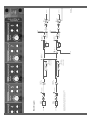
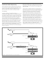
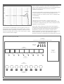
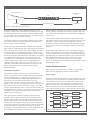
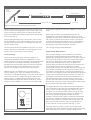
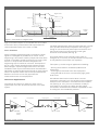
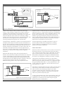
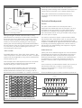
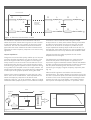
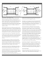
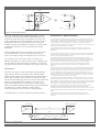
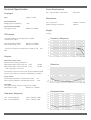
Applications Notes:
Driver in a Box
A Harman International Company
MIX AMP
INPUT
JUMPER
OPTIONS
LINE
MIX AMP
PHASE REV.
PHASE REV.
BLOCK DIAGRAM SHOWS FIRST TWO INPUTS AS EXAMPLE
REMAINING INPUTS ARE SIMILARLY CONSTRUCTED
INPUT 2
INPUT 1
INPUT
JUMPER
OPTIONS
LINE
Block Diagram
GAIN TRIM
-6dB to +14dB
GAIN TRIM
-6dB to +14dB
DEFAULT=UNITY
+10dB GAIN
JUMPER OPTION
RETURN
SEND
DEFAULT=UNITY
+10dB GAIN
JUMPER OPTION
RETURN
FADER/INSERT
SEND
FADER/INSERT
LINK TO 3
INSERT OUT
INSERT IN
LINK 1-2
SILK
SILK
OUTPUT LEVEL
TRIM PRESET
SILK OUT
SILK IN
METER 2
OUTPUT LEVEL
TRIM PRESET
SILK OUT
SILK IN
METER 1
MUTE
MUTE
POWER UP
MUTE CONTROL
OUTPUT 2
OUTPUT 1
Applications Notes:
Driver in a Box
Contents
Part 1: Traditional Audio Engineering
! Line sending in concert systems
! Linking distant parts of a broadcast
complex
! Avoiding ground noise from digital, video
and power circuits
! Optimising common mode rejection
! Multi-way distribution amplifiers
! Matching levels from DVD & other
systems
Part 2: Audio Enhancement
! Unbalanced inserts on mixers
! Input modes and level boosting from
-10dBV sources
! Achieving high (+26dBu) drive levels
! Digital audio workstations
! PC sound cards
! Digital audio mixers
! Sonic enhancement and the "Mr. Rupert
Neve sound”
Part 3: Advanced applications
! Gain structure of the DIB.
! Additive and subtractive broadcast clean
feeds
! DIB as an extended virtual earth mixer for
foldback/matrix sends
! DIB insert points
! Wiring external linear and/or rotary faders
to the DIB.
! The "Pure Path" mixing console
Part 4: Technical Background
You will find references to [Notes:] in this section.
! The behaviour of balanced lines
! Cable losses
! Output impedance
! Typical response curves
! Cable/interface resonance
! 600 Ohm loading
! Differential inputs and common mode
rejection
! Ground potentials
! Circulating noise currents
Part 5: Architects' specification
Cross References
[Note:]
Many of the benefits obtained from the Driver in
a Box (DIB) stem from a very high level of audio
performance and it follows from this, that some of
the issues involved are of a technical nature. To
make for easy reading, the more technical issues
have been placed in a separate section towards
the end of these notes. The earlier text explains
the practical benefits and the technical
explanations are easily found by following the
cross-reference system.
Traditional Audio Engineering
Audio engineering is about using electronics to get sound
from one place to another, generally along copper cables,
with the only changes to the sound being those you
choose to make. Many things can happen to sound after it
leaves the audio mixer where it is usually controlled.
Line Sending
Consider a typical concert situation(see Fig. 1) microphones on stage, perhaps a mic. splitter at the side of
the stage driving cables to the front of house mixer. More
long cables, probably multicore, sending controlled signals
from the front of house mixer to amplifier racks, often also
near the stage and separate feeds also to a foldback
mixer. The first cause for concern is the ability of the front
of house mixer, or very often the graphic equalisers, to
drive the long cables. In some cases outputs may not even
be balanced, but even if they are, questions of the cable
behaviour [Note:1] and the graphic equaliser's output
impedance [Note:2] become important factors. Sometimes
losses on the return feeds to the foldback mixer and to the
amplifier racks can be large, perhaps 5dB or more at
20kHz which makes a nonsense of any carefully designed
frequency response!
Because the AMEK DIB is an eight channel device with
total isolation of the signals, choosing only the most critical
signals can allow one or two DIBs to cover foldback and
amp. rack feeds.
Using a DIB as a sending amplifier can minimise these
losses and also reduce the risk of noise being injected onto
the line but problems are not always limited to losses and
interference. The output circuit can interact with cable
reactance to produce a resonant circuit - the type of
network used in some equalisers - and this can cause
peaks, often just above the audio band! Whilst this can
sometimes give rise to audible effects, it can also cause
instability (oscillations) in the system [Note:3]. Unlike much
equipment, DIB is well able to drive low impedances so a
600 ohm load can be placed at the remote end of the
cable, giving useful damping of any resonance and further
improving the supersonic smoothness as shown in the
curve overleaf. It may be necessary to adjust the internal
output trim control to make up the level loss of around 1 dB
that will be caused by the 600 ohm load but these trimmers
have a range in excess of +3/-3dB and can also be used to
make up other system losses. These can occur in
installations with extra long cable runs such as stadiums.
Mic. splitter
FOH Mixer
Foldback
mixer
Graphic equaliser
Amplifier Racks
Mic. splitter
DIB
FOH Mixer
Foldback
mixer
Graphic equaliser
DIB
Amplifier Racks
Figure 1: Typical connections in a concert situation.
When shipped, the DIB is accurately calibrated to unity
gain for high impedance loads so do not make adjustments
unless you have good reason and any necessary
calibration equipment!
AMPL(dBu) vs FREQ(Hz)
5.0000
4.0000
3.0000
100k Ohm
2.0000
The issues illustrated by the concert example can be found
in other situations, for example sending signals from a
broadcast studio to a master control room in a distant part
of the building.
1.0000
0.0
600 Ohm
-1.000
Line Receiving
-2.000
This time we'll use the studio / master control room
example (see Fig. 3, over) to consider the benefits of DIB
as a receiver of signals though the same principles can be
applied in concert systems.
-3.000
-4.000
-5.000
10
100
1k
10k
100k 200k
One of the major issues that arises with input stages is
mismatching caused by differences in ground potential. In
an ideal environment, the technical and safety earths
distributed to all parts of the system, maybe even in
different buildings, would all be at exactly the same perfect
earth potential. In the real world this doesn't happen
because all manner of equipment is creating earth currents
The trimmers are adjusted by removing the top cover as
described in the User Guide, taking careful note of safety
procedures! When adjusting the controls, take care not to
come into contact with any part of the mains power supply
which contains lethal voltages.
Figure 2: Internal Layout of DIB
Output
link jumpers
(replaced by rear panel switches on later models)
Insert gain
jumpers
Output
transformers
DANGER
HIGH
VOLTAGES
1
2
3
4
5
6
7
8
Output
level trims
Input
transformers
1
2
3
4
5
Input sensitivity
jumpers
6
7
8
Studio sound desk
Master control
matrix
DIB
Local earth
Potential difference!
Local earth
Figure 3: Studio/Master control room
at mains frequencies, video frequencies and an entire
spectrum of data clock frequencies! No matter how careful
the earthing scheme and how thick the earth cables, earth
at one location will never be the same as at another and all
this can mean noise problems [Note:5].
Inserting the DIB gives an extremely high level of isolation
to the audio signal so potential differences between two
earths cease to cause problems.
[Note:4] A further enhancement provided by the DIB is a
high common mode rejection ratio. We hope that all master
control matrices have inputs with a good CMRR. However,
it can be useful to crosspatch signals from a control room
in a distant part of the broadcast complex to other circuits
with less good input characteristics. Time delays may need
to be patched in to maintain lip-sync and the inputs of
many delays are optimised for cost effectiveness when
used in audio control rooms, not to be high grade line
receivers. Once again, this may require only two or four
channels of the eight channel DIB, leaving scope for one
DIB to address a number of master control needs
simultaneously!
Distribution Amplifier
The DIB can function to feed one or more signals to a
variety of destinations with complete isolation between the
various destinations. It is much more powerful than a
conventional distribution amplifier because as well as its
special input and output characteristics, it can be
configured in a variety of ways. Pressing the "LINK 1-2"
switch on the rear panel (or adjusting an internal jumper on
early DIBs) causes output 2 as well as output 1 to be fed
with the signal applied to input 1 and controlled by the front
panel gain knob of channel 1. The internal trimmers remain
available to allow separate adjustment of output levels
when required (See Fig. 4).
Also operating the "LINK 2-3" switch routes the same
channel 1 input signal to output 3 and by pressing more
buttons, more totally isolated feeds of the channel 1 input
can be obtained. Not only can DIB become a distribution
amplifier with up to eight outputs, but it can be configured
to give fewer outputs from the first input, with the remained
functioning either as single channel drivers or in other
groupings. For example channels 1 and 4 could both have
three outputs with channel 7 having two outputs.
It is important to remember that when a channel has its link
switch pressed, that input no longer drives that output, but
the transformer balanced input is still available feeding the
insert send.
The extremely high isolation between signal paths in the
DIB means that the input and output sections can be used
separately, output sections giving a high performance
distribution amplifier, whilst some of the otherwise unused
input sections can be providing high quality line receiving
circuits.
Proper buffering is important when multi-channel signals,
such as those from DVD players, are to be distributed to a
variety of destinations. Most readily available DVD players
provide audio on unbalanced "phono" type outputs and the
DIB's eight channels can provide a convenient way to
convert these to a robust "professional" format audio
signal, for distribution around entertainment venues as well
as production areas.
Audio Enhancement
Apart from the using the DIB to interface to long cables,
there are also applications within localised areas.
Insert points
All serious audio mixing consoles have insert points in their
channels, groups and outputs for patching effects devices.
The majority in use today have insert sends and a large
proportion have insert returns which are unbalanced. In
many instances this works adequately, particularly if all
effects equipment has been carefully installed. However, a
pressured recording session is just the time when a newly
1
Input 1
2
Input 2
3
Input 3
Output 1
1
Output 2
2
Output 3
3
Output 4
4
Link 1-2
Link 2-3
Link 3-4
4
Input 4
to 5 etc.
Figure 4: Link switches
Sound
desk
channel
Effects device
DIB
Local earth
Potential difference!
Local earth
Figure 5: Connection to mixing console inserts
added unbalanced item can give problems and the worst
time for technical investigations! This is when DIB comes
to the rescue by providing even a modest console with
some fully balanced and totally isolated insert sends and
returns (See Fig. 5).
[Note:6] Using the DIB only on the send or return circuit
can be sufficient to solve some problems, but if you have
enough DIB channels to spare, isolating both send and
return is always wise!
lower than the signals nominally at +4dBu (i.e. wrt to 0.775
volts).
Whilst DAT and other long established formats are
available with professional balanced outputs, it can be
expedient to buffer semi-professional equipment. However,
with newer formats such as DVD a choice is not always
available. Buffering with a DIB can prove a cost effective
way to achieve balanced outputs and avoid extensive
interfacing through domestic phono sockets!
Console insert sends are sometimes not at the "+4" level
used in other parts of the studio and the DIB gain control
can be used to give full drive when needed.
The "mixing" setting is described later.
Level Boosting
Serious audio editing is now possible on workstations
using quite modest analogue audio facilities and such
digital audio workstations (DAWs) have a number of points
in common with console inserts! The inputs and outputs
are often not balanced so all the issues discussed in
[Note:4] and [Note:6] come into play. In addition PC
systems using sound cards powered from a computer do
not have high enough supply voltages to produce
professional levels of over +20dBu. Good sound cards can
have excellent analogue audio inputs and outputs when
connected to single devices. Unfortunately the design of
many PC power supplies means that although the dynamic
range at the sound card connector can be very wide, it is
impossible to achieve the lowest noise performance in a
real installation because of power supply noise on the
ground. The DIB comes into play providing total isolation
between the noisy ground of the computer(s) and the clean
ground of the rest of the audio installation.
Levels through the DIB input and insert stages are
restricted to +22dBu to match the capabilities of most
studio equipment. However, when the highest signal levels
are required, the full +26dBu capability of DIB can be
exploited using the internal output trim controls. The DIB
can then be set to provide +26dBu levels, even from
sources only capable of more modest output levels.]
Additional gain is provided by the "Input Sensitivity"
jumpers (See Fig. 6). They are located near the input
transformers. The default setting is unity gain which means
with all controls at "0", +4dBu input gives +4dBu output.
Moving them to +12dB increases the sensitivity to suit
semi-professional equipment where the level on "phono"
sockets is often -10dBV (i.e. wrt one volt) so about 12dB
I/P txfr
Unity
+12dB
Mixing
Figure 6: Input sensitivity jumpers
Digital Audio Workstations
The eight channels of the DIB conveniently complement
many workstations and also low cost digital audio mixers,
many of which provide analogue I/O in blocks of eight
channels. Low cost digital audio mixers should not have
the same risk of power supply noise as PC systems as
they are specifically designed for audio purposes.
However, the inputs and outputs, sometimes unbalanced,
are often not robust for sending and receiving from long
cables [Note:5] [Note:6]. Here the DIB can be used with
the input and output sections split by pressing the four
"insert" buttons on the rear panel (See Fig. 7, over).
The input sections are then used to give a high grade
balanced input. Each unbalanced insert send is connected
via a short cable to a mixer (or DAW) analogue input.
Digital mixer
Mixer I/P
Mixer O/P
Insert send
Insert return
High
grade
input
Robust
output
Chassis
Figure 7: Connection to a digital mixer
Eight mixer/DAW outputs are connected with short cables
to the insert return points and the DIB outputs become
robust balanced outputs of the mixer or DAW.
Sonic Subtleties
All the preceding applications help to maintain the audio
signal as unchanged as possible but of course sound
engineering is also about creativity! Rupert Neve has been
a leader in the field of subtle sound control for many years
and it is no surprise that the DIB is designed in the
engineering style for which he is famous. One aspect of
this is a "silky" quality heard since his earliest transistor
based designs. A special stage called "SILK" has been
included in each output of the DIB and can be switched in
individually to enhance that special sound on those outputs
where it is required. Others can be left unprocessed with
distortion and noise so low, they approach the
measurement limits of test equipment!
Advanced Applications
The DIB can be used as an adjunct to other control
systems but it can also be used as the core of an audio
system.
Input
Front panel
0dB/+12dB/MIX
(virtual
earth)
-6/+14dB
Figure 8: Levels jumpers
Insert point
Mix Amplifiers
The eight channels have internal jumpers that are normally
set to provide balanced input amplifiers with unity gain,
though of course the front panel input level controls and
the internal output level trimmers allow other gain
structures to be devised (See Fig. 8).
An unusual feature is the internal jumper option to
configure all (or as many of the input sections as required)
as fully balanced virtual earth mix amplifiers.
This opens up a wide range of applications including:
* deriving clean feeds for broadcast (additive and
subtractive)
* summing line level feeds from other equipment
* using the DIB as the core of an extremely high grade
audio mixer.
A broadcast clean feed is used to allow a remote
contributor to be sent a mix of everything in the broadcast,
except his own contribution. If he listens to the complete
mix (See Fig. 9, over), his own contribution is likely to
come back to him with a time delay and this makes
conversation awkward and sometimes impossible as well
as raising the risk of feedback problems.
Insert gain
0/+10dB
Insert in
Output trim
±3dB
REMOTE CONTRIBUTOR
DIB MIX CHANNEL
Contributor
(post fade)
Studio mics
"Lo"
Studio CDs etc.
STUDIO SOUND DESK
5K1
"Hi"
Transmission
+
5K1
Clean feed
-
"Lo"
"Hi"
Transmission
DIB
Clean feed
Figure 9: Cleanfeed
There are two ways to derive a clean feed. On large
mixers, a spare auxiliary send can be used to create an
"additive" clean feed which sums together all sources,
except the remote contributor. When there is no spare aux
send, the DIB can make such a mix externally, adding
together post fade signals from the required channels. This
can result in a lot of signals to be summed, though
summing selected sub-groups can minimise this.
resistors. Even a modest 24 input, 8 output foldback matrix
requires 24 x 8 x 2 = 384 resistors (See Fig. 10)! Whilst the
circuit is extremely simple, care is needed to achieve a tidy
layout which allows every incoming cable screen to be
linked to a good ground point. This ground must be the
same as that going into the DIB so any cable between the
mixing resistors and the DIB input connector should be
kept as short as possible to prevent noise.
The alternative "subtractive" system is one which takes the
complete studio output and removes the unwanted part of
the mix. This is done by inverting the polarity (phase) of the
signal to be subtracted then summing it with the total mix,
thereby producing a cancellation. For this to work well, it is
necessary that signal levels are correctly adjusted and
there are no serious phase shifts or time delays within the
control room, however the mixing scheme is greatly
simplified.
Careful engineering is needed if the DIB is to give its
optimum performance when configured as a mixing
system. AMEK's UK headquarters will be pleased to
advise in any cases of difficulty.
Because DIB mixing is done with fully balanced mix
busses, the noise and crosstalk performance can meet and
in some cases better the performance of the finest audio
mixers on the market giving results well beyond what can
be captured with most digital recorders. However, this level
of performance requires care with the installation.
Balanced mixing means every input requires two 5K1
Input 1
(balanced)
Input 1 "Hi"
Input 2 "Hi"
Input 3 "Hi"
Input 4 "Hi"
Input 1 "Lo"
Input 2 "Lo"
Input 3 "Lo"
Input 4 "Lo"
5K1
VE channel
+
5K1
-
Inputs 2-4
(similar)
Figure 10: Virtual earth mixing
Insert and Faders
When the DIB is used as the core of a system, level control
becomes important. Front panel level controls provide a
"trim" function but full fader control is desirable. The insert
point on each channel of the DIB can be used to insert
other pieces of equipment, though its unbalanced sends
and returns are designed to simplify connection of faders.
Insert points are enabled in pairs by four push button
switches on the rear panel. Do not switch them in, unless
there is wiring to the insert connector or no signal will pass!
Any good quality linear fader, or rotary potentiometer, with
a track resistance of between 1K and 10K Ohms can be
used (See Fig. 11, over).
Separately screened cables must be used for the send and
return wiring. This means two screen connections to the
fader and two to the chassis ground pin in the DIB
connector. Whilst using twin and screen cable may look
simpler, it will give frequency response errors when the
fader is anywhere except fully open.
If rotary potentiometers are used, choose quality types with
a logarithmic law. Low cost log. law devices can give poor
matching so controls set to the same angle may give
different amounts of attenuation.
matrix between the CIB and the DIB. If any kind of
switching system is being used, remember to keep the 5K1
resistors close to the DIB, not to a distant switch panel.
Fader
Cable 1
Cable 2
Many other combinations can be devised and your
imagination can be allowed to fully explore the DIB's
versatility!
Technical Background
Send 1
Return 1
24
25
12
Chassis ground
Figure 11: Inserting a fader
Having extra gain "in hand" when the fader or rotary
potentiometer is at maximum is often useful. The DIB can
be configured to have 10dB of gain in the insert return
circuit so it gives unity gain with the faders 10dB below
maximum. This is done by isolating the mains supply,
opening the unit and following the procedure described in
the User Manual. Then fit a jumper across each of the pair
of "Insert Gain" pins before replacing the cover and
reconnecting the mains input.
"CIB" and DIB
The AMEK DIB has two "Pure Path" sister products - the
"Stem Compressor" and the "Channel in a Box". Complete
systems can be configured by using various combinations
of these (See Fig. 12).
This example has the DIB inputs all set to be virtual earth
mix points, faders connected at the insert points and
outputs feeding into a Stem Compressor.
The system can be simplified, with some inputs being
simple level devices without equalisation, by making a
direction balanced connection and not using a CIB. An
enhancement can be the addition of a switch or electronic
General
For years, audio wisdom has correctly been that if
equipment has unbalanced inputs and outputs, it is not a
good idea to use long cables. It is often believed that if
connections are balanced, line length ceases to be an
issue and cables can be as long as needed. Sadly, things
are never quite so simple!
It is useful to look at how inputs, outputs and the cables
that connect them really behave when in use and from this,
it begins to be apparent that not all balanced inputs and
outputs are created equal. Significant benefits are obtained
by sending and receiving signals with a device made for
that purpose. By understanding what happens to signals,
we see why this is true.
Cable Behaviour
[Note:1] Of course, balanced signals are more robust than
unbalanced ones, but they are still subject to the laws of
physics! Whatever cable is used it has three important
electrical characteristics - resistance (R), capacitance (C)
and inductance (L). These characteristics combine to
produce a network which is approximately like Fig. 13,
over.
It isn't necessary to understand the details, but it is easy to
see that the circuit has a number of components in
common with equalisers i.e. things which change the
frequency response!
Of course different types of cable have different values for
Channel in a Box
Faders
DIB
Stem Compressor
Figure 12: Example of a Pure Path® mixing system
circuit element
R
L
R
C
R
L
L
R
L
C
element is
repeated
many times
L
R
R
L
Figure 13: Electrical characteristics of cable
the resistance, capacitance and inductance and short
cables have lower values than long ones. A rule of thumb
is that thick cables with more copper in them have lower
resistance, but even the thickest and lowest resistance
types still have some resistance and the inductance and
capacitance mean frequency response errors can be very
significant.
could have a loss of 5dB at 21kHz using the simple
analysis above. In reality other effects relating to the cable
and the input and output circuits come into play and the
behaviour in all cases is not simple to predict but a low
output impedance certainly helps avoid such roll offs. For
example the same cable driven by an output impedance of
100 Ohms has a loss of only 1dB at 21kHz instead of 5dB.
Output Impedance
[Note:3] Consider the cable equivalent circuit, further
simplified and re-arranged.
Things are not too bad with quality cables up to a few tens
of metres long but the cable is only part of the story. The
device driving the cable has a big effect on what signal
finally comes out at the far end. Let's consider the sort of
arrangement often found in a live concert situation with a
mixer driving a graphic equaliser and the equaliser driving
a long cable to the amplifier racks. To simplify matters, we
will ignore the inductance of our cable and any inductance
in the output of the graphic equaliser driving the cable.
[Note:2] If the output impedance is more than just a few
ohms, even as low as 600 Ohms, cable capacitance will
cause the frequency response to fall above some
frequency (See Fig. 14). As an example, 100m of a typical
installation cable (100pF/m) driven from a 600 Ohm output
The inductance and capacitance form a resonant circuit
which causes peaks. These peaks are typically in the
supersonic region somewhere between 30kHz and 200kHz
and the overall performance becomes complex to calculate
with HF peaks combining with rolls offs from various
causes to give a highly irregular frequency response (See
Fig. 15).
Video and RF engineers are familiar with the need to
terminate lines. This means placing a load at the end of the
line with a resistance equal to the characteristic impedance
of the line. This is not usually important in analogue audio
systems, but with very long cables, a terminating resistor
can improve the frequency response. In particular, it can
cable
equaliser
output
amplifier
input
Ro
C
Ri
level
Ro
frequency
Figure 14: Output Impedance
cable
output
R
Ro
Ro
input
L
level
C
R
Ri
level
L
frequency
Figure 15: Resonance
reduce the size of any resonant peaks which occur in the
supersonic region. With the DIB, a 600 ohm load is a
suitable value to add to the end of long cables and will give
much smoother supersonic performance. It will also reduce
the overall signal level by around 1dB but this can be
compensated with the internal output level trim control.
Input Stages
Now let's think about the effect input stages can have on
the behaviour of interconnected equipment.
Electronically balanced inputs provide good performance in
many applications but have some limitations as receivers
from long lines. There are three main risks. Two relate to
the lack of ground isolation and the third concerns the
input's ability to reject signals that are not properly
balanced.
The assumption that makes balanced lines desirable is
that the signal is a "differential" one. This means that it has
a "hi" side and a "lo" side with the signal on one side being
Voltage on the
"hi" wire
Voltage on the
"lo" wire
Figure 16: Balanced waveform
exactly the opposite as that on the other, shown by the
waveforms below (See Fig. 16, solid lines).
At a balanced input, the circuit subtracts the voltage on the
"lo" wire from that on the "hi" to derive the desired input
signal. In other words, its has derived the difference
between the two wires which is why it is called a
"differential input".
Balanced circuits are good at rejecting noise that may be
picked up in the interconnecting cable because most noise
signals affect both the "hi" and "lo" wires almost identically
as shown by the dotted lines. When the input circuit does
its subtraction, the noise on both the "hi" and "lo" wires is
the same so is cancelled. For this process to work perfectly
the noise on the two wires must be identical but the input
amplifier must also be capable of doing a perfect
subtraction with no errors. Real input amplifiers are never
this perfect and a small amount of the noise signal that
was common to the "hi" and "lo" wires (the "common mode
signal") gets through the input and is mixed with the audio.
The ability of input amplifiers to avoid this noise is called
break
output
cable
input
output
cable
input
X
current
Ri
no current?
Ri
Figure 17: Balanced input driven from a balanced output
the "common mode rejection ratio".
[Note:4] For a whole range of reasons, electronically
balanced amplifiers are difficult to design with good
common mode rejection ratios at all frequencies. A circuit
good at rejecting mains hum and other low frequency
noises, may not work as well at the high frequencies which
cause radio breakthrough. Quality transformers are a
proven solution that can give good common mode rejection
(CMMR) figures across a wide range of frequencies. The
larger the negative number for CMMR, the better the
rejection of noise.
Output circuits also have a complementary performance
aspect called "output balance". For perfect operation, the
audio signal on the "hi" and "lo" sides must be identical but
inverted to each other. Electronically balanced outputs can
provide slightly different drive to the "hi" and "lo" sides, so
impairing the noise rejection. Using a transformer output is
an effective way to ensure a good output balance figure.
A balanced input driven from a balanced output can be
thought of as a simple circuit with current flowing along one
leg, through the input and back up the other leg (See Fig.
17). Of course the signal is an AC one so the current
keeps reversing direction but this doesn't affect our
analysis.
If the circuit is broken, a simple view might be that all
signal should disappear as current can no longer flow
around the circuit but sadly this rarely happens! In most
cases the signal drops slightly but does not disappear.
Whilst this might be useful if our cables are faulty, it does
not help good noise performance which is after all why
balanced circuits were adopted in the first place!
The reason the signal does not disappear starts to be
apparent when we see a more accurate approximation of
the electronically balanced input circuit (See Fig. 18).
The electronically balanced input stage has an input
impedance between the "Hi" and "Lo" terminals (Zi), but
there are also impedances, which for the sake of simplicity
we can think of for now as resistances, between each of
these "legs" and ground (Zh and Zl). These are
unavoidable with electronic balanced inputs because of the
need for all the electronics to be referenced to it's power
supplies. The drawing to the right of Fig. 18 shows the
same circuit but is rearranged for clarity!
Although the "Hi" terminal is open circuit current still flows
through the input impedance Zi and is amplified as any
other received signal! In reality, these impedances are not
simple resistances but a complex mixture, mainly of
resistance and capacitance so the signal that gets through
often has a modified frequency response.
Of course we hope our cables don't cause one leg to
become open circuit but what we are really looking at is
any situation where the signal on the "Hi" side is not a
perfect mirror of that on the "Lo" side. This is something
which does happen very commonly when noise is injected
onto a cable. If we are very lucky exactly equal amounts of
noise might be injected onto both the high side and low
sides of the cable and our balanced input can then cancel
this "common mode" signal. Sadly, in the real world it is
usual for the noise injected onto the two legs of the cable
to be slightly different. Fortunately this difference is
attenuated by the three impedances Zh, Zl and Zi. If Zh
and Zl could be made infinitely high, this attenuation can
become perfect and we can get something close to
complete rejection of line noise. Although Rupert Neve and
AMEK produced a very close approximation to this with
their "Transformer Like Amplifier" stage, a real transformer
is a secure way to ensure noise immunity.
This points us towards an important requirement for our
ideal receiving amplifier - transformer coupling - but this
also gives another important benefit. An input that has no
reference to earth avoids problems when connecting
equipment that is operating with differences in ground
potential. This can happen when the pieces of equipment
are physically distant and connected via long cables.
Ground Potentials
[Note:5] The difference in grounds often shows as a
voltage at mains power frequency and can be several volts
or tens of volts - often larger than the audio signal!
input
Hi
X
Hi
Zi
=
Lo
Zh
X
Zi
Lo
Zl
Zl
Zh
Scn
Scn
Figure 18: Ground potential
Hum can sometimes be avoided by breaking a screen
connection but with electronically balanced inputs and
outputs the noise will only be cancelled if it is within the
range of levels that can be handled by the input stage. If
ground differences are several tens of volts, the input
amplifier can be overloaded even before any audio signal
is applied and mixtures of hum and audio are hardly
desirable!
[Note:6] Matters get even worse when inputs and output
are unbalanced as it is often impossible to break the
screen connection, being an essential part of the circuit.
Fig. 19 shows the "send" part of the connection, but
identical problems can occur with the return. Adding a DIB
can provide fully balanced insert connections so avoiding
the ground loop and the circulating noise signal, often hum.
Conclusions
The only safe way to make connections using anything
other than the shortest, carefully made and laid studio
cables is with transformer coupling both at outputs and at
inputs. Many modern mixers and other devices provide
only electronic balancing, and some are not even balanced
and can cause catastrophic problems. Several of the
effects described occur in the supersonic region above
20kHz but AMEK and Rupert Neve have long stressed that
the behaviour of audio systems in these regions
contributes greatly to the "sound" of audio systems.
The AMEK Driver In A Box avoids all of these problems.
Architects' Specification
The driver/mixer unit shall be housed in a steel enclosure with dimensions of 445mm
(17.52") wide (excluding the front panel projections for rack fixing), by 44.5mm (1.75")
high by 308mm (12.13”) deep. The enclosure shall be of a style and have fixing holes
to suit standard 19" rack enclosures with an overall front panel width of 482mm
(18.98"). All surfaces shall be durable against the normal wear and tear experienced in
professional studio and related environments.
The unit shall be mains powered from AC supplies of either 50Hz or 60Hz and
amplitudes between 100 volts and 240 volts without requiring any switch or other
adjustments.
All audio inputs and outputs should be on 25 pin Sub-D type connectors with provision
for them to be securely locked in place. The mains input should employ a detachable
lead with a rear panel IEC (CEE22) connector.
There shall be eight separate audio channels having a high degree of isolation
between them to facilitate their independent use. Facilities shall be provided to allow
the linking of adjacent channels into groups of two or more channels. Each of the eight
inputs and outputs should have transformer coupling to provide a high degree of
ground isolation. The overall design should minimise susceptibility to radiated
electromagnetic fields and the unit must not be a source of significant levels of
radiation.
Each of the eight input channels shall have a front panel illuminated push button switch
providing a phase reverse (polarity invert) function and a front panel level adjustment
having a range of -6dB to +14dB. Channels shall also have insert points on the rear
panel with switching provided to place the insert points of adjacent channels in or out
of circuit. This insert point is to be unbalanced to facilitate the connection of external
faders and provision must be made for these to operate with a path gain of either 0dB
or +10dB when the fader is in the fully open position.
An additional 12dB gain shall be selectable to individual inputs by the use of internal
jumpers. Each input shall be able to function as a fully balanced virtual earth mix buss
by the addition of external summing resistors. All eight output stages shall be equipped
with separate level meters calibrated from -30dB to +10dB and illuminated push button
mute switches. Level adjustment shall be provided with internal controls.
The frequency response shall extend several octaves beyond the traditional audio
bandwidth with harmonic distortion at 1kHz less than 0.001%. Special audio
processing shall be separately switchable into each of the outputs to give a sonic effect
similar to that provided by "Class A" audio mixing consoles designed in the 1970s and
1980s.
All controls and indicators shall be clearly labelled with their functions and
comprehensive supporting literature shall be provided to describe their correct
operation.
Insert send
Effects device input
"Hi"
Scn
Circulating noise current
Figure 19: Unbalanced
Technical Specification
Power Requirements
Line Input
AC ~ input 50-60Hz, 100V-240V
Gain
-6dB to +14dB
Input Impedance
Bridging Input Impedance
>10kW
Input Balance (CMRR)
Unity gain @1kHz
Better than -65dBu
Max 30W
Dimensions
19” 1U rack unit
Depth including connectors
482mm x 44.5mm
382mm
Weight
5.75 kg
THD+Noise
Unity gain setting, input/output level +10dBu,
measured at output
Frequency Response
5.0
4.0
(Bandwidth 22Hz-22kHz)
THD measured @ 1kHz
Better than -98dBu
Better than 0.001%
...figures for distortion are identical for loads of 10kW
600W .
3.0
2.0
1.0
and
10KW
0.0
-2.0
-3.0
-4.0
-5.0
Outputs
Maximum Output Level
Balanced and floating transformer
Measured at Main output with 10kW
Measured at Main output with 600W
...with output gain at nominal.
load
load
+23dBu
+22dBu
The internal output trim control can give an additional 4dB
of gain. The maximum output drive capability is +26dBu
Insert Points
Send output impedance, unbalanced @1kHz
Return input impedance, unbalanced @1kHz
600W
10
0.5
1K
10K
Load
100K 200K
Distortion
0.01
50W
100kW
0.001
0.0005
-50.0
Frequency Response
load impedance
load impedance
100
0.1
Crosstalk
Unity gain setting, Insert IN, output level +10dBu
Measured @ 1kHz
Better than -100dBu
10kW
600W
Load
-1.0
20
100
1K
10K
1K
10K
20K
Bandpass Noise
-60.0
10Hz - 200kHz (-2dB)
10Hz - 120kHz (-3dB
-70.0
-80.0
-90.0
-100.0
-110.0
-120.0
-130.0
20
100
20K
A Harman International Company
International Headquarters
Langley House
Third Avenue
Trafford Park
Manchester
M17 1FG
Tel: +44 (0) 161 868 2400
Fax: +44 (0) 161 873 8010
Web: www.amek.com
Email: [email protected]
US Headquarters
1449, Donelson Pike
Airpark Business Centre 12
Nashville
TN37217
Tel: +1 888 286 9358
Fax: +1 615 360 0273
Los Angeles
2740, W Magnolia Blvd
#102
Burbank
CA91505
Tel: +1 800 585 6875
Fax: +1 818 973 1622
Tokyo
3-5-14, Konan
Minato-ku
Tokyo
108-0075
Tel: +81 (0) 3 5707 0575
Fax: +81 (0) 3 5707 0599
The company has an established policy of seeking improvements to
the design, specifications and manufacture of its products. Alterations
take place continually, often without prior notification outside the
company. The contents of the company's literature must not be
regarded as an infallible guide to the specifications available despite
considerable effort to produce up-to-date information. No literature
constitutes an offer for sale of any particular console or product. The
company's officially appointed distributors and representatives will
advise on any changes when the circumstances of the enquiry permit.
© 2000 Harman International Industries Ltd.