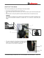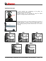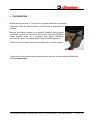
1
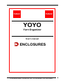
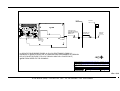
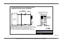
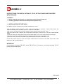
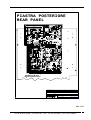
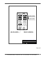
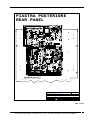
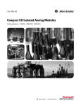
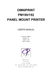
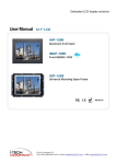
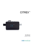
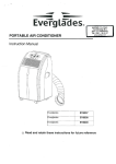
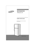
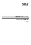
YOYO
Yarn Organizer
User’s manual
ING046-01.doc
APRIL ’09 V01/ING
25124 Brescia (Italia) – Via San Polo, 183 – Tel. 030 2300492 – Fax. 030 2300833
25124 Brescia (Italy) – Via San Polo, 183 – Tel. 030 2300492 – Fax. 030 2300833
YOYO
1
WARNINGS
This manual is an integral part of YOYO unit and must be read carefully before
starting using it.
YOYO device must NOT be used in explosive rooms.
YOYO has been expressly devised to work as yarn feeder.
It must be used as mentioned in this manual only.
Dinema is not responsible in case of wrong or improper use and in case of any use
different from what provided by this manual.
Moreover, Dinema is not responsible when YOYO is used by unskilled people, when it
is unproperly power supplied, in case of unauthorized modifications and/or repairs, in
case of serious failures in planned maintenance or when spare parts used are not
original or are not specific for the model considered.
Any alteration or modification is forbidden, specially referring to protections and
safety parts.
Be sure that plant voltage is the one required by YOYO device.
Before any maintenance or cleaning operations, be sure that power supply is off.
YOYO device must be disposed according to regulations in force in the countries
where it is sold.
This manual must be kept, for eventual future references.
When the device is handed over to others, the producer should be informed about the
address of the new owner. In this way, sending eventual manual updatings to the new
customer will be easier.
DINEMA reserves the right to modify the product and/or the present manual without
any notice.
25124 Brescia (Italy) – Via San Polo, 183 – Tel. 030 2300492 – Fax. 030 2300833
YOYO
2
Regulations and directives
YoYo device has been carried out and tested according to technical specifications and to all
applicable checking- and testing-standards.
It complies particularly with:
- EN ISO 12100-1
Safety of machinery – Basic concepts, general principles for design Part 1: Basic terinology, methodology.
- EN ISO 12100-2
Safety of machinery – Basic concepts, general principles for design Part 2: Technical principles.
- EN 60204-1
Safety of machinery –
Part 1: General Requirements
Electrical
Equipment
of
Machines
-
The device herein described, complies with the requirements of following directives:
- 2004/108/CE
- 2006/95/CE
- 2006/42/CE
EMC Directive
Low Voltage Directive
Machinery Directive
YOYO device complies with above mentioned regulations and directives only when used
together with the fittings provided.
Any different configuration may require particular adjustments to get the conformity.
25124 Brescia (Italy) – Via San Polo, 183 – Tel. 030 2300492 – Fax. 030 2300833
YOYO
3
INDEX
1. DESCRIPTION
♦ YoYo…………………………………………………………...
♦ PCB 4725 CAN CONTROLLER……………………...........
♦ PCB 3858 INTERFACE 12 YoYo………………………..…
2. TECHNICAL FEATURES ……..………………….
♦ YOYO TECHNICAL DEVICE………………………………..
3. INSTALLATION………………………...………….
♦ INSTALLATION OF PCB 4725……………………………..
♦ INSTALLATION OF PCB 3858……………………………..
♦ INSTALLATION OF YOYO DEVICE…………………….…
FIXING……………………………………………………...
HOW TO PUT THE YARN IN ……………………………..
WINDING SPACING……………………….......................
♦ CALIBRATION……………………….……………………….
4. YOYO MAINTENANCE OPERATIONS …………
♦ CALIBRATION...……………………….………………………
♦ CLEANING……………………………………………………..
♦ AFTER SALES TECHNICAL ASSISTANCE..……………..
5. DEVICE DISPOSAL …………………………..….
Page 5
Page 5
Page 7
Page 8
Page 9
Page 9
Page 10
Page 10
Page 10
Page 11
Page 11
Page.12
Page 13
Page 14
Page 15
Page 15
Page 15
Page 15
Page 16
6. ENCLOSURES
25124 Brescia (Italy) – Via San Polo, 183 – Tel. 030 2300492 – Fax. 030 2300833
YOYO
4
DESCRIPTION
♦ YoYo
25124 Brescia (Italy) – Via San Polo, 183 – Tel. 030 2300492 – Fax. 030 2300833
YOYO
5
Yo Yo device is used to control yarn feeding to knitting machines.
The distinctive feature of this device is the possibility to be programmed to feed the yarn
changing the tension depending on the phase of garment production. Once the tension
needed is set, Yo Yo device is able to keep the yarn tensions unchanged for each yarn
working phase.
Yarn feeding tension is due to revolution speed of yarn winding pulley.
After this pulley there is a sensor measuring yarn tension. When the sensor detects any
difference between the tension set and the one measured, it transmits to the motor the
necessary speed adjustment to get the correct yarn tension again.
Two male connectors are available on Yo Yo rear side: J2 and J3.
J2 connector is used for service operations only. J3 connector is needed for connection of
Yo Yo device to the machine, through PCBs 4725 and 3858 whose descriptions follows.
25124 Brescia (Italy) – Via San Polo, 183 – Tel. 030 2300492 – Fax. 030 2300833
YOYO
6
J3 CONNECTOR
PIN #
1
2
3
4
5
6
SIGNAL
24V
24V
CANL
CANH
GND
GND
V min
21.6 Vdc
21.6 Vdc
-36 Vdc
-36 Vdc
-
V max
26.4 Vdc
26.4 Vdc
36 Vdc
36 Vdc
-
I max
-100 / -600 uA
-200 / 30 uA
-
NOTE
Nominal 24V
Nominal 24V
Low level can voltage (imput/output)
High level can voltage (imput/output)
♦ PCB 4725 CAN CONTROLLER
The main function of PCB 4725 is the conversion of parallel signals coming from machine
data BUS into the serial protocol “CAN” of Yo Yo device and viceversa.
25124 Brescia (Italy) – Via San Polo, 183 – Tel. 030 2300492 – Fax. 030 2300833
YOYO
7
The use of CAN CONTROLLER is not necessary if machine is already equipped
with PCB 2008.
J3 connector is used to connect PCB 4725 to the board “INTERFACE 12 YOYO” here
below described.
J1 and J2 connect PCB 4725 to the DATA BUS coming from machine.
J4 is needed for the connection of power supply board.
FT1 faston must be always earth connected by a yellow-green wire with proper
section.
♦ PCB 3858 INTERFACE 12 YOYO
PCB 3858 is the interface between YoYo and machine.
It’s possible to connect up to 12 YoYo devices (J5/J16).
J3 connector is used to connect the board to the
communication system “CAN”.
J1 connector is used to connect the power supply board.
When the machine has to be equipped with more than 12
Yo Yo (max. 24), PCB 3858 can be extended through
connection to another PCB 3858, by means of J2 and J4
connectors.
25124 Brescia (Italy) – Via San Polo, 183 – Tel. 030 2300492 – Fax. 030 2300833
YOYO
8
THECHNICAL FEATURES
All technical features of YoYo device are here below stated.
♦ YOYO TECHNICAL FEATURES
Dimensions
Height
Depth
Width
200 mm (max)
70 mm
75 mm (fixing hook not included)
Weight
0,4 Kg
Temperature
On working conditions
On standoff
During shipment
0 ÷ +40 °C
0 ÷ +50 °C
-15 ÷ +85 °C
Power Supply
Min and max voltage
Nominal voltage
Max power absorbed on steady conditions
21,6 ÷ 26,4 Vdc
24 Vdc
12 W
Relative Humidity
(without condensations)
On working conditions 20 °C
40 ÷ 80 %
Altitude (above sea level)
0 ÷ 2000 m
About the yarn
Max. yarn speed
Tension
Tension resolution
25 m/sec.
1 ÷ 50 g
0,5 g
25124 Brescia (Italy) – Via San Polo, 183 – Tel. 030 2300492 – Fax. 030 2300833
YOYO
9
INSTALLATION
♦ INSTALLATION OF PCB 4725
Installation procedure of PCB 4725 may be different depending on machine model.
For further details see the document “installation instructions” herewith enclosed.
♦ INSTALLATION OF PCB 3858
PCB 3858 must be fixed on the specific bracket included in the KIT supplied by Dinema.
For further details see the document “installation instructions” herewith enclosed.
25124 Brescia (Italy) – Via San Polo, 183 – Tel. 030 2300492 – Fax. 030 2300833
YOYO 10
♦ INSTALLATION OF YOYO DEVICE
FIXING
YoYo device must be fixed on the specific “support ring”:
•
•
Hook the Yo Yo on the support ring, by means of the fixing hook;
Tighten the fixing screw placed inside the Yo Yo hook, by using an allen screw of 3 mm.
Eventual Yo Yo vibrations due to wrong fixing can affect the quality of final product.
25124 Brescia (Italy) – Via San Polo, 183 – Tel. 030 2300492 – Fax. 030 2300833
YOYO
11
HOW TO PUT THE YARN IN
The correct proceeding for yarn positioning is here below stated:
•
•
•
Put the yarn into the eyelet for yarn incoming (1)
Open the brake disks and thread the yarn into the ceramic eyelet inside the brake shaft
(2).
Wind the yarn on the pulley and the ceramic shaft as shown in the pictures (3) (4).
REMARK
The number of windings on the pulley and the shaft has to be stated considering yarn
type and environmental conditions, to enable then Yo Yo device to unwind the yarn
easily.
3
3
1
2
4
•
The yarn coming from the pulley must pass over the
sensor for tension measuring (5) and after that, it
has to be put into the eyelet for outgoing (6).
5
6
25124 Brescia (Italy) – Via San Polo, 183 – Tel. 030 2300492 – Fax. 030 2300833
YOYO 12
WINDINGS SPACING
To avoid eventual yarn overlapping on the pulley, the
windings must be properly spaced.
Windings spacing can be adjusted by using the “adjust
screws”, to change ceramic shaft inclination.
Windings spacing has to be stated considering the number of
windings effected, in order to cover the whole width of the
pulley. Winding spacing must be effected when YoYo device
is running.
No
No
YES
No
YES
25124 Brescia (Italy) – Via San Polo, 183 – Tel. 030 2300492 – Fax. 030 2300833
YOYO
13
♦ CALIBRATION
Before starting the use of YoYo device, a proper calibration is required.
Calibration must be effected when YoYo device is powered but
stopped.
Be sure that tension sensor is on standoff condition and proceed
as follows: remove the yarn from the sensor and keep ENABLE
button pushed down for 7 seconds long; when calibration
succeeds the green led makes three flashing and than goes off.
At this moment, the yarn has to be repositioned on tension sensor.
To assure the exact result when measuring yarn tension, a new calibration should be
effected periodically.
25124 Brescia (Italy) – Via San Polo, 183 – Tel. 030 2300492 – Fax. 030 2300833
YOYO 14
MAINTENANCE
♦ CLEANING
No particular maintenance operations are required but just usual cleaning.
YoYo device has to be cleaned by using a wet cloth only, if necessary some neutral soap
can be added.
NEVER use any solvent or alcool
♦ AFTER SALES TECHNICAL ASSISTANCE
Dinema S.p.A. offers to the customer the support of a skilled technical staff, to solve any
eventual problem faced when using and maintaining the machine.
25124 Brescia (Italy) – Via San Polo, 183 – Tel. 030 2300492 – Fax. 030 2300833
YOYO
15
DISPOSAL OF YOYO UNIT
WARNING!
To avoid any possible negative effect on both environment and health and to
promote materials recycle, YoYo device must be disposed according to the
regulations in force in the countries where it has been sold.
25124 Brescia (Italy) – Via San Polo, 183 – Tel. 030 2300492 – Fax. 030 2300833
YOYO
16
YOYO
Yarn Organizer
User’s manual
ENCLOSURES
25124 Brescia (Italia) – Via San Polo, 183 – Tel. 030 2300492 – Fax. 030 2300833
ANNEX 1
HOW TO INSTALL THE YOYO KIT FOR LONATI UNIFY MACHINES WITH PCB 2004:
Installation must be effected when machine is off, discovering the rear movable plate of the
electronic box.
WARNING!!
• Before installing the yoyo kit, it is necessary to switch the main power off.
• Following operations must be executed by skilled operators only.
1) Installation of PCB 4725 on machine already equipped with PV 029 (Machine with
colour display):
Machines with colour display are already equipped with PV 029. Replace it by the PV 029
included in the kit. After that fix PCB 4725, referring to sheet T001 and using the material
provided.
2) Installation of PCB 4725 on machine with no PV 029 (Machine with black/white display):
Machines with black/white display have not PV 029. Install the one included in the kit, referring
to sheet T003. After that fix PCB 4725 to PV 029 referring to sheet T001 and using the material
provided.
3) Connection of PCB 4725:
Disconnect the flat cable plugged into J2 connector of PCB 2004 and J6 connector of PCB 1114
(rack board).
Connect CVP 267 (total length 900mm) supplied with the kit between J1 connector of PCB
4725, J2 connector of PCB 2004 and J6 connector of PCB 2004, referring to sheet T004.
Plug into J4 connector of PCB 4725 the corresponding Modu2 female connector of CBL 4131
cable ; screw the wire “0V” of CBL 4131 into pole 4 of J6 connector of PCB 2004 and screw the
wire “+5V” of CBL 4131 into pole 2 of J16 connector of PCB 2004.
Plug into J3 connector of PCB 4725 the corresponding 9-pole male connector of CBL 4128 and
fix the connector to the PCB 4725 by means of the two spacers supplied.
Connect the wire “FL 381” to FT1 faston of PCB 4725; the eyelet of FL 381 must be then
connected to the closest earth screw.
4) Connection of PCB 3858:
PCB 3858 must be fixed to PM 674 and then to machine structure referring to sheet T002.
Connect to J1 connector of PCB 3858, the corresponding Modu1 female connector of CBL 4130
coming from the power supply box.
Connect to J3 connector of PCB 3858 the corresponding Modu2 female connector of CBL 4128
coming from J3 connector of PCB 4725.
Connect YOYO devices to one of the 6-pole Modu2 female connectors of PCB 3858 through
cable CBL 4531(450 mm) or cable CBL 4532 (1000 mm).
IMPORTANT!
It’s necessary to connect CBL 4531 and/or CBL 4532 to YoYo device, on the side showing “YOYO”
printing (the shielded side).
Enc. 1/12
25124 Brescia (Italia) – Via San Polo, 183 – Tel. 030 2300492 – Fax. 030 2300833
PV 029
J1
1
J1
J2
1
J2
PV 029
W3
R15 R16 R17 R18 R19
U4
C20
U5
C21
U6
U8
C19
RT2
C17
Y1
C18
R12 R13
TP4
U7
TP3
C6
RN1
R4
R5
Q1
DS1
R1
C9
R9
U2
TP1
C4
C11
C7
C2 C3
DS2
C16
C12
L1
R10
RT1
FL1
R2
1
R3
C5
C10
R6
R8 C8 Q2
U1
TP2
R11
J8
J7
FT1
DISTANZ.18/7
SPACER 18/7
DADO M3
DADE M3
W1
J5
W2
R7
VR1
U3
J3
ROND. DENT. M3
TOOTHED WASHER M3
VITE TC+ 3X6
SCREW 3X6
C13
C14
C15
DS3
PCB 4725
R14
J4
PCB 4725
FORO N°1
HOLE NO.1
LA PCB 4725 DEVE ESSERE FISSATA AL PV 029 SFRUTTANDO IL FORO N°1
PRESENTE SU QUEST'ULTIMO; PER IL FISSAGGIO FARE RIFERIMENTO AL DISEGNO!
PCB 4725 MUST BE FIXED TO PV 029 THROUGH HOLE NO.1 PLACED ON IT;
WHEN FIXING REFER TO THE DRAWING!
APPARECCHIATURA: KIT YOYO PER M/C UNIFY (PCB 2004)
FOGLIO: T001_D02
DESCRIZIONE: Montaggio PCB 4725 su PV 029.
ULTIMA MODIFICA:Sostituita PCB 3727 con PCB 4725. Eliminate rondelle in nylon.
NOTE: .
R
S.p.A.
DISEGNATORE: Mauro Pellegrini
CLIENTE: Lonati
DATA: 10/10/2007
Enc. 2/12
25124 Brescia (Italia) – Via San Polo, 183 – Tel. 030 2300492 – Fax. 030 2300833
C1
J6
MONTAGGIO PCB 3858 SU PM 674 CON DISTANZIALI IN NYLON
ASSEMBLING PCB 3858 ON PM 674 BY NYLON SPACERS
PM 674
FORO N°1
HOLE NO.1
DISTANZIALE NYLON
NYLON SPACERS
PCB 3858
VISTA TOPOGRAFICA PCB 3858
COMPONENTS VIEW OF PCB 3858
FORO N°2
HOLE NO.2
1 J4
J2
1
DS1
J5
1
J11
1
R2
J6
1
J12
1
J7
1
J13
1
J8
1
J14
1
J9
1
J15
1
J10
1
J16
1
PM 674
RT1
C1
CBL 4126 (YOYO)
CBL 4129 (YOYO)
RT2
C2
PCB 3858
R1
1
FORO N°3
HOLE NO.3
FORO N°4
HOLE NO.4
J1
CBL 4130 (24 VDC)
1 J3
CBL 4128 (CAN BUS)
MONTARE N°4 DISTANZIALI IN NYLON SUL PM 674 NEI FORI N°1-2-3-4,
DOPODICHE' FISSARE LA PCB 3858 AI DISTANZIALI STESSI (VEDI DISEGNO).
FIX THE NO.4 NYLON SPACERS ON PM 674 INTO HOLES 1-2-3-4,
AFTER THAT FIX PCB 3858 TO THE SAME SPACERS (SEE THE DRAWING).
APPARECCHIATURA: KIT YOYO PER M/C UNIFY (PCB 2004)
FOGLIO: T002_D01
Montaggio PCB 3858 su PM 674 con distanziali in nylon e connessione
DESCRIZIONE: della PCB 3858.
ULTIMA MODIFICA: Inserite viste e note.
NOTE: .
R
S.p.A.
DISEGNATORE: Mauro Pellegrini
CLIENTE: Lonati
DATA: 10/05/2007
Enc. 3/12
25124 Brescia (Italia) – Via San Polo, 183 – Tel. 030 2300492 – Fax. 030 2300833
PCB 2004
R2
Q1
1
D1
R67
R90 R83 R81
1
R109
C6 7
DS 24
R 126
R 204
U129
R3 57
J23
1
DS 26
J40
1 J25
R T11
U116
U117
U118
U119
U120
U121
R314
R 315
R316
R 317
R318
R 319
D50
Q13
J26
TP 4
RT12
RT13
1
J 27
D39
D38
D37
R342
D36
1
J2 8
R3 43
D51
R 359 R36 0
R 36 9
C214
D40
R 355
U124
C221
R363
R36 2
D S2 2
DADO M3
DADE M3
DADO M3
DADE M3
FORO N°A
HOLE NO.A
FORO N°C
HOLE NO.C
DISTANZ.18/30
SPACER 18/30
DISTANZ.18/15
SPACER 18/15
DADO M3
DADE M3
J19
1
V R8
R 287
C20 7
Q14
Q 15
1
R 277
VITE TC+ 3X6
SCREW 3X6
ROND. DENT. M3
TOOTHED WASHER M3
ROND. DENT. M3
TOOTHED WASHER M3
DISTANZ.18/12
SPACER 18/12
R298
C218
R365
R364
J21
1
U115
R 313
R341
R324
R 312
V R6
R 311
R340
D49
R35 2
D48
D47
D46
R351
R350
R349
R34 8
D45
D44
R34 7
D43
R34 6
J 24
U114
R T5
U 97
C 189
R 27 9
DS 43
R325
R T9
R3 54
1
U113
D S 42
J17
R 221
R297
U112
R30 2
DS 41
D S44
U111
R30 1
D35
R 300
D S4 0
R339
U110
Q12
DS 39
R33 8
U109
R310
D33
U108
R 309
D S38
D34
U107
R30 8
DS 37
R337
U106
R 307
R2 76
R336
U105
R 306
DS 36
R 27 1
R2 72
R 29 0 R 2 75
U104
R 305
R323
U103
R 304
R2 70
R 291
D S34 D S 35
Q10 R 281
R2 69
DS 33
R2 67
R2 68
D S32
V R5
1
DS 25
R 2 32
R 2 33
R 2 34
R 2 35
R 2 36
R 2 37
R 2 38
R 2 39
R 24 0
R 24 1
R 2 42
D S3 1
R285
C187
D S30
U102
D42
J29
C188
R2 73
R2 95
R2 96 R274
1
D32
1
D S28 D S 29
R 303
R3 35
C220
R T8
R358
C204
R293
DS 47
V R10
R34 5
U 10 1
R2 94
RT7
RT6
C206
W5
R344
R3 34
R3 33
U128
J 22
R 286
R322
Q11
D S 27
V R4
U 93
DADO M3
DADE M3
1
R130
RT4
U 83
R36 6
D52
D29
D31
U9 9
U12 3
R 299 C 202
U9 8
C 217
C211
C 222
R356
R368
C161
C 178
R 2 26
J3 5
K3
C223
R3 32
C 205
U 94
U8 6
C18 6
C219
C 216
T P3
R2 66
C192
C198
RT 10
C215
R2 65
D41
R3 30
C20 3
C20 9
C213
R33 1
C185
C2 01
R282
C212
R 26 4
R 27 8
C 194
R2 84
C 197
U12 6
R 28 3
R2 92
C2 10
U96
U95
V R7
R3 29
C19 1
C 19 6
R 2 28
R 2 29
R 23 0
R 23 1 C 17 6
D27
U9 2
C 18 0
R 263
C195
U8 5
U 84
1
R3 27
R 32 8
C18 2
C 184
C 19 3
C 200
R 289
C 208
R 321
U 122
R2 88
V R9
R 32 0
FL5
U 91
C 18 1
C 179
U100
1
FL 4
1
J20
C 147
C 170
R 22 0
2 3 4 5 6 7 8
R 262
C190
R2 80
C199
R18 4
D 22
R2 03
S3
R261
J14
R182
R 199
U12 5
1
R161
R168
L2
RN 11
ON
FL 3
R149
C 146
C16 6
C171
ROND. DENT. M3
TOOTHED WASHER M3
VITE TC+ 3X6
SCREW 3X6
R 143
R160
U72
C15 7
R 198
U82
R6 3
R 61
FORO N°C
HOLE NO.C
C 10 6
R138
C136
J 16
J18
D2
C11
W4
C14 0
U75
R 196 R197
FL 2
R 94
R9 2 C60
D S17
R 17 5
D S23
R 19 5
R194
1
C17
R27
C13 0
FORO N°A
HOLE NO.A
C 134
R142
C 127
1
R145
R169
C 12 2
DISTANZ.18/30
SPACER 18/30
FORO N°B
HOLE NO.B
C111
R 139
C 116 U 60
R 148
R 15 1
C 13 1 U 63
R 164
R 166
C 139 U 69
R 177
R 147
C12 1
R150
C 10 5
D S13 U 58
D14
R146
C 124
C123
C 129 R 156 R 15 7 R15 8
R 155
R129
R137
R14 0 R14 1
Y1
C 125
R 370
R3 72
R37 1
R154
U 59
D15
R 163
U 57
U 12 7
1
R187
C 156
ROND. DENT. M3
TOOTHED WASHER M3
VITE TC+ 3X6
SCREW 3X6
J12
R12 1
C10 1
R167
U73
R117
D S11 U 54
D S20
R 193
1
R113
C89
U53
R128
C112
U80
D 21
V R3
U 47 C84
D17
D S19
C 145
D S9
R116
R119
U 55
C 138
U70
R112
R17 8
R162
R106
R107
U 43
C 80
U4 0
D S7
R353 R326
U6 4
C15 0
R 115
C 83
C93
R 13 6
R144
W3
D20
R111
C100
RN 9
2 3 4 5 6 7 8
R153
1
U61
D S18
D19
R 10 5
DS6
C69
R98
R100
R102
R103
C160
C99
S2
ON
R134
D S14
C13 2
J15
TP2
C79
DS 45
C98
R 135
R 133
C 128
R 152
1
C115
R18 3
U 41
J10
R T3
R95
R 97
K2
D9
J31
C97
R 124
C109
C108
C 107
DS5
V R2
D S10 U 51 C90
U52
R125
RN8
R 132
R13 1
R 89
U 32
R120
R 159
D18
Q7
DS4
Q6
R 93
J 34
J13
R165
R26 R17
RN 6
J8
1
C88
U33
C7 0
FORO N°B
HOLE NO.B
U4 5
C86
C87
C104
R12 7
C102
C103
PV 029
C71
C77
C 96
C114
C 49
VR 1
R8 6
DS 12
C113
R 77
C 65
R 123
D12
D13
RT1
RT2
C61
R 114
C 82
R 118
C 85
DS 46
C58
U 30
C7 6
C78
PV 029
J9
B3
U23
K1
J32
U42
U50
F T1
R62
U22
R74 C5 0
U3 4
R 96
R 99
R 101
C81
U21
B2
C39
C52
R108
L1
J36
J38
B1
R5 7
C57
R104
D11
J3 7
J39
R76
R8 4
1
D10
R51
C 48
R82 C56
R85
R87 R88
R 91
C 68
B T1
J11
W6
C36
R 56
C 38
R 60
D3
C4 6
J6
FL1
R48
C 34
C3 5
J33
C5 3
C59
C 75
U20
R6 4
C47
R65
C41
C45
68
C4 4
C5 5
U 31
C 37
R7 3
U 24
R80
C5 4
D7
D8
U15
R42
R45
DS1
PCB 2004
TP1
C43
67
Q3
Q5
R79
R78
W2
C12
U14
R12
C25
C 27
R 39
DS2
J7
36
R7 0
Q4
D5
D6
W1
U10
35
R 72
C 18
R3
C3
R6
R5
C16
R9
C 26
34
R71
C28
33
R69
R68
U4
U6
U 12
C 42
S1
R25
U2
C2
R4
C6
U3
C13
R2 8
D4
R66
U9
R16
C23
R1
C1
U1
1
R15
C2 2
U19
R59
C40
C10
R24
1
U18
U7
U8
U11
U 17
U16
C9
C21
R75
R33
C 32
J30
J3
R 14
C 15
D S3
Q2
C5
R23
C3 3
R3 4
C31
C30
C 19
U13
R N5
C2 9
R19
R36
R18
C 24
R11
C14
C8
R10
C7
C2 0 C4
R 13
R 22
R35
R30
J5
R29
R N3
U5
PK
RN 4
RN 2
1
J4
R8
R21
R32
R38
R41
R44
R47
R50
R53
R55
1
J2
1
R7
R2 0
R31
R3 7
R4 0
R4 3
R4 6
R4 9
R5 2
R5 4
R58
1
J1
RN1
1
R 36 1
R36 7
IL PV 029 DEVE ESSERE FISSATO ALLA PCB 2004 SFRUTTANDO I FORI N°A-B-C;
PER IL FISSAGGIO FARE RIFERIMENTO AL DISEGNO!
PV 029 MUST BE FIXED TO PCB 2004 THROUGH HOLES NO. A-B-C;
WHEN FIXING REFER TO THE DRAWING!
APPARECCHIATURA: KIT YOYO PER M/C UNIFY (PCB 2004)
FOGLIO: T003_D00
DESCRIZIONE: Montaggio PV 029 su PCB 2004 nelle M/C con display bianco/nero.
ULTIMA MODIFICA: .
.
NOTE: .
R
S.p.A.
DISEGNATORE: Mauro Pellegrini
CLIENTE: Lonati
DATA: 10/05/2007
Enc. 4/12
25124 Brescia (Italia) – Via San Polo, 183 – Tel. 030 2300492 – Fax. 030 2300833
CVP 267
PCB 4725 (J1)
CVP 267
CVP 267
CVP 267
CVP 267
CVP 267
CVP 267
CVP 267
PCB 2004 (J2)
PCB 1114 (J6)
APPARECCHIATURA: KIT YOYO PER M/C UNIFY (PCB 2004)
FOGLIO: T004_D00
DESCRIZIONE: Connessione del CVP 267 alle PCB 4725-2004-1114.
ULTIMA MODIFICA: .
.
NOTE: .
R
S.p.A.
DISEGNATORE: Mauro Pellegrini
CLIENTE: Lonati
DATA: 10/10/2007
Enc. 5/12
25124 Brescia (Italia) – Via San Polo, 183 – Tel. 030 2300492 – Fax. 030 2300833
ANNEX 2:
INSTRUCTIONS FOR INSTALLATION OF YOYO KIT ON CE MACHINE EQUIPPED
WITH PCB 2008
WARNING!!
• Before installing the YOYO kit, it is necessary to switch the main power off.
• Following operations must be executed by slilled operators only.
1. INSTALLATION OF PCB 3858/1
Pcb 3858/1 must be mounted on the holder, installed on the creel.
Plug the Modu1 female connector of CBL. 4130, coming from J1 connector of local power source SK
3787A/1 mounted on the machine, into the J1 connector of SK 3858.
Plug J2 conn. of local power source SK 3787A/1 into the terminal strip of the CBL. 0999.
Plug the 3 faston of CBL. 0999 into the corresponding male faston connectors 12,17 and 22 of the D4840496
board.
Connect to earth, the earth eyelet coming from the CBL.0999, by one of the screws placed on the plate.
Plug the J3 connector of SK the 3858, into the female modu2 connector of the CBL. 4127.
Connect the J24 connector of SK 2008, to the modu2 female connector of the CBL. 4127.
Connect the YOYO devices to one of the 6-pole modu2 female connectors of SK 3858, by the CBL. 4532
(450mm) or CBL. 4532 (1000mm).
IMPORTANT
It’s necessary to connect CBL 4531 and/or CBL 4532 to YoYo device, on the side showing “YOYO”
printing (the shielded side).
Enc. 6/12
25124 Brescia (Italia) – Via San Polo, 183 – Tel. 030 2300492 – Fax. 030 2300833
J16
J18
J46
D22
J21
RT29
RT28
J24
RT27
J47
J28
J36
J68
R402
R298
R373
DS28
J39
C27
R486
1
U118
R513
R514
VR38
R161
R180
R193
R169
R159
C20
U69
U67
R282
R273
R264
R238
C49
C48
TP6
R197 RT26
U86
C150
U98
R403
R376
W19
W18
C166
U60
U57
W8
TP11
1
J38
J37
J35
J34
RT30
J30
J29
J27
J26
J25
U55
U51
U47
U35
U32
U31
U30
W7
R284
R206
W6
DS15
R160
R196
R171
R559
R121
DS43
RT9
J3
1 J10
1
C216
C161
TP18 TP19
C218
R411
W5
DS29
U36
K6
R188
R74
R73
R172
TP3
R34
U8
R33
U7
L6
U112
W20
U81
C130
U94
R256
U77
DS31
C212
R482
DS40
C204
U66
U38
R179
R216
R279
DS30
C119
C129
C122
R321
R255
TP5
TP4
C227
DS5
U11
L1
C91
C162
U83
R358
DS21 DS22
R214
U37
R297
R306
R110
R112
DS4
U10
R35
R36
R71
R32
U6
R72
R31
U5
DS3
U4
U3
R83 DS2
R30
J9
J2
U1
R29
1
1
1 J85
C7
W25
J8
J1
R24
1
1
R80 R81
R45
J19
J23
J22
Q6
W24
RT8
VR24
R448
R450
R508
U115
U95
C125
TP7
C105
DS17
B1
S1
W23
C93
J67
R246
C94
R248
U63
R440
R438
R442
U103
R415
C151
U84
R338
R327
Q20
Q19
DS6
U117
S2
U64
J44
K1
C210
L3
U99
U27
Q4
U33
DS35
C79
C41
L4
DS27
U50
U28
Q5
R150
RT6
RT7
R148
DS41
J5 8
J57
R398
U93
R397
C146
C133
C126
R359 DS33
D65
TP8
R153
J61
R339
J60
C160
W15
C75
R229
R199
R203
DS13
R92
J4
R12
DS1
R66
R233
R565
DS37
DS36
1
J11
C109 J59
C169
R394
J62
R326
U72
R308
C74
J63
C217
J33
K3
R195
DS19
U45
1
J55
K2
1
U101
DS34
W16
C106
DS26
C206
W21
J65
DS18
U44
R245
W13
U71
J66 J64
R395
C143
C136
C138
C127
C134
DS25
DS24
Q18
W1
R191
Q27
R243
R362
C110
U62
R240
R242
DS16
R190
Q17
K4
U42
Y1
C148
C137
R377
R378
J7
RT1
U39
R239
D57
C121
C86
1
RT13
Q28
R194
C77
R287
D50
R286
DS32
R301
U70
R325
J41
R422
R421
J31
U61
U52
R300
C92
C73
C53
U29
U13
J6
J14
R217
1
1
R423
RT10
J43
C100
R360
R381
R363
C120
U114
C184
R57
R128
R129
DS9
U18
R58
U20
R131
R133
DS10
R551 R548 R546
R529
W17
FT1
1 J45
RT34
DS38
C185
U104
TP9
U88
U82
FL1
U76
C81
R134
R135
DS11
U22
R59
R41
R552
R265
L2
1
J42
1
W10
W11
R464
R462
R444
U49
R236
VR5
R278
DS23
Q26
C80
RT16
R207
R260 C67
DS20
C76
R424
U96
U89
U85
U79
R118
C32
TP2
U26
W3
Q9
RT2
J13
C186
TP13
FL2
B2
R328
C102
U58
U56
U53
U48
R138
DS12
U24
R60
R42
R137
C153
TP17
C191
C171
W14
W9
C68
C101
R561
R272
R562
R251
R530 R208
TP10
R317
R 52 6
TP16
TP12
+5V DC POWER
R393
R396
C158
R399
C170
U74
U59
J5
1 J12
R126
R125
C40
R123
DS8
DS7
R56
U17
U14
R122
U34
R37
R55
D15
RT3
VR25
R453
RT5
RT12
RT17
RT21
R39
RT4
VR26
VR31
VR30
D40
TP1
R117
RT22
RT24
VR27
VR32
R181
RT11
R346
VR8
C99
R342
R345
R536
R349
VR9
R329
VR10
R281
R370
R385
R350
R353
VR11
RT18
RT19
VR23
R371
VR18
VR14
VR6
VR16
VR28
R454
VR29
R457
R492
R494
R
VR39 R488
R490
S.p.A.
VR33
R459
R40 8
VR7
VR17
R392
VR21
R116
1
VR37 R485
R142
D17
R509
U105
C173
J56
J40
J32
J5
C28
D1
J10
TP3
C59
C79
C70
C43
D3
R39
D5
C12
U14
U35
D2
U24
J14
R54
C54
U18
C23
VR2
R36
J6
RN2
RN1
1
R40
U25
U54
U48
U44
C80
U41
R74
U39
U36
U30
R41
C13
C16
J1
D4
C94
C84
R79
R78
C64
R60
D6
R50
C38
U31 R53
C44
R57
R64
U15
R45 R46
R48
C29
W2
VR1
R26
U8
U1
C1
J3
R47
U27
C105
R101
U50
R66
U3
J4
TP1
U42
C88
C92
U51 R97
R98
U57
C87
C71
R75
R62
R63
R58
C82 R81
R51
RN4
U20
C3
C41
R55
R19
R22
R25
R27
R32
R35
C60
U13
R14 R15
R3
U40
U45
U32
C37
W1
C17
C18
C24
C36
C65
U26
U12
U2
C2
PCB 2007
R511
U92
VR15
R387
R389
R355
VR34
VR19
VR20
R357
VR13
VR12
D28
D36
D3
R6
D4
R7
D5
R8
D6
R9
D7
R10
VR35
RT31
1
1
R497
1
RT36
D S4 2
R410
D46
D27
D35
D8
R11
R535
R274
R250
R275
VR4
R176
R178
1
R419
R303
R544
R113
R420
1
VR22
1
R501
1
R505
1
R504
R304
D41
R318
R319
C107
C60
Q12
1
D16
D60
U126
D13
R563
U121
D20
1
Q13
R38
R114
D18
D66
R48
D78
R46
U123
R331
C222
W2
R531
RT20
RT25
R40
D67
D11
R542
C231
C229
W26
R257
D19
R115
U127
C220
R182
C108
1
1
1
TP15
1
1
1
PCB 2008
RT33
U4
R24
R20
R18
C4
S1
C89
U46
J13
U37
J17
C106
R37
U53
C53
U59
C32
C34
C99
C95
U47
D8 D9
L1
R8
C83
C85
R21
C51
C50
Q3
R13
C8
C9
J8
R88
U43
Q6
FL1
J16
C100
U56 C101
C103
Q4
U60
U55
VR4
R100
R99
C93
W6
R90
C96 C97
U49
R82
BT1
D7
J9
C102
C91
FT1
TP2
J11
J12
W4
R70
D14
TP4
D13
L2
Q5 D11
R85
D10
C104
DS2
R91
R94
C66
C67
C58
C61
C63
C55
C56
U33
C69
C40
R80
S2
R56
R83 R84
VR3
C78
C74 C76
C77
C73
U38
C49
U29
C6
C75
U6
C35
U22
C20
C22
U17
R28
R34
D12
C72
C46 C48
C47 C45
C31
Q2
C11 U9
R23
R77 DS1 R76
R65
C62
R68
R69
R71
R72
C68
R93
RN6
DS3
U28
U21
C7
R2
R11 R12
R7
R33
R10
U7
J2
R6
R17
R9
Y1
U16
C19
C21
C42
R95
R96
R16
C5
C10
R61
C57
C30
C33
R38
C90
C81
R73
R67
U5
R31
C26
U34
RN5
C52
Y2
U23
C98
C39
Y3
U58
U52
R59
R52
C27
C25
U19
R5
U11
C14 R29 R30 C15
J7
U10
RN3
R4
R1
Q1
1
RT35
R42
R43
R44
1 J15
RT23
R228
1 J17
1 J20
W12
1
C147
1
W3
1
1
ON
RT32
68
DS39
68
1
1
1
R379
1 2 3 4
1 3 2
1
36
1 2 3 4 5 6
VR3
R211
1
67
R 38 0
34
1
1
35
W22
PK
1
33
67
R89
1
36
1
1
35
1
34
C86
33
R92
1
R86
PK
R87
1
1
1
1
PIASTRA POSTERIORE
REAR PANEL
1
PCB 2008 J24 (CBL 4127)
APPARECCHIATURA:Kit YOYO per M/C Lonati Modulare Donna FOGLIO: T001_D01
DESCRIZIONE: Vista piastra posteriore.
ULTIMA MODIFICA: Aggiornato disegno.
.
NOTE: .
DISEGNATORE: Mauro Pellegrini
CLIENTE: Lonati
DATA: 24/09/2007
Enc. 7/12
25124 Brescia (Italia) – Via San Polo, 183 – Tel. 030 2300492 – Fax. 030 2300833
PIASTRA ANTERIORE
1
1
C1
J5
J2
J1
C5
1
C2
J3
J5
C6
1
J3
C2
C5
1
J4
C3
C4
C8
C7
C6
FT2
FT2
1
1
1
J10
1
1
J2
C1
1
1
1
J1
J6
J7
J11
1
1
1
1
1
J10
J6
J7
J8
J9
C10
C10
C9
FT1
C11
C9
1
J11
C12
C11
C13
C14
FT1
ALIMENTATORE RES OFF-LINE
(24Vdc 250W)
Optional per YOYO
C14
J3
J2
6
5
4
F3
3
2
F2
1
32
F1
25
S
R
26
19
13
18
12
11
T
30
14
J4
17
16
28
27
24
23
J5
22
21
10
15
20
9
8
7
J6
J1
APPARECCHIATURA: Kit YOYO per M/C Lonati Modulare Donna FOGLIO: T003_D00
DESCRIZIONE: Vista montaggio alimentatore 24Vdc (PCB 3787A/1).
ULTIMA MODIFICA: .
.
NOTE: .
R
S.p.A.
DISEGNATORE: Mauro Pellegrini
CLIENTE: Lonati
DATA: 24/09/2007
Enc. 8/12
25124 Brescia (Italia) – Via San Polo, 183 – Tel. 030 2300492 – Fax. 030 2300833
1 J4
J2
1
DS1
J5
1
J11
1
CBL 4531 (YOYO)
R2
J6
1
J12
1
J7
1
J13
1
J8
1
J14
1
J9
1
J15
1
J10
1
J16
1
RT1
C1
CBL 4532 (YOYO)
RT2
C2
R1
1
J1
1 J3
CBL 4130 (+24VDC)
CBL 4127 (LINEA CAN)
APPARECCHIATURA: Kit YOYO per M/C Lonati Modulare Donna FOGLIO: T002_D01
DESCRIZIONE: Vista PCB 3858.
ULTIMA MODIFICA: Aggiornato disegno.
.
NOTE: .
R
S.p.A.
DISEGNATORE: Mauro Pellegrini
CLIENTE: Lonati
DATA: 24/09/2007
Enc. 9/12
25124 Brescia (Italia) – Via San Polo, 183 – Tel. 030 2300492 – Fax. 030 2300833
ANNEX 3
INSTRUCTIONS FOR INSTALLATION OF YOYO KIT ON CE MACHINE EQUIPPED
WITH PCB 2008 – LONATI MODULAR GOAL MACHINES
WARNING!!
•
Before installing the YOYO kit, it is necessary to switch the main power off.
•
Following operations must be executed by skilled operators only.
PCB 3858 CONNECTION:
PCB 3858 must be installed on the fixing clamp arranged on machine structure.
Connect J1 connector of PCB 3858 with the corresponding Modu1 female connector of CBL 4370 cable. On
the other end this cable has to be connected to the +24Vdc terminal box of machine.
Connect J3 connector of PCB 3858 with the corresponding Modu2 female connector of CBL 4127 cable.
Connect J24 connector of PCB 2008 with the corresponding Modu2 female connector of CBL 4127 cable.
Connect YOYO devices to one of Modu2 6-pole female connectors of PCB 3858, by means of CBL 4531 cable
(450mm) or CBL 4532 (1000mm) cable.
IMPORTANT
It’s necessary to connect CBL 4531 and/or CBL 4532 to YoYo device, on the side showing “YOYO”
printing (the shielded side).
Enc. 10/12
25124 Brescia (Italia) – Via San Polo, 183 – Tel. 030 2300492 – Fax. 030 2300833
J16
J18
J46
D22
J21
RT29
RT28
J24
RT27
J47
J28
J36
1
J39
1
J38
J37
J35
J34
RT30
J30
J29
J27
J26
1
1
J9
J2
1 J85
J25
J6 8
R402
R298
R373
W18
C166
U118
R513
U69
U67
U86
C150
W19
TP11
U98
R403
R376
R514
VR38
R486
U60
R282
U57
W8
DS28
R273
U55
R238
C49
C48
C216
TP6
R197 RT26
R180
R193
R169
R161
C27
R159
C20
W7
U51
U47
U35
U32
U31
U30
DS3
R264
R284
R206
W6
DS15
R160
R196
R171
R559
R121
DS43
U6
R71
R32
R72
R31
U5
U1
C7
U4
U3
R83 DS2
R24
R30
J8
W25 R29
J1
R80 R81
R45
1
1
J19
J23
J22
Q6
W24
RT8
VR23
J3
1 J10
1
C161
TP18 TP19
C218
R411
W5
DS29
U36
K6
R188
R74
R73
R172
TP3
R34
U8
R33
U7
L6
U112
W20
U81
C130
R112
DS4
R110
U94
C129
C122
C119
U77
C212
R482
DS40
C204
DS31
DS30
U66
R279
L1
C91
C162
U83
R358
DS21 DS22
R256
U38
R179
C227
DS5
U11
R36
D8
R11
R216
TP5
TP4
R255
R214
U37
R297
R321
R306
R35
U10
R508
U115
R421
J31
U61
U52
U95
J41
R422
C125
R325
U70
TP7
C105
B1
S1
W23
C93
J67
R246
C94
R440
R438
R442
U103
R415
C151
U84
Q20
Q19
DS1
DS6
U117
S2
U64
J44
K1
C210
L3
U99
U27
Q4
U33
DS35
C79
C41
L4
DS27
U50
U28
Q5
R150
RT6
RT7
R148
DS41
J58
J57
R398
U93
R397
C146
C133
C126
R359 DS33
D65
TP8
R153
J61
R339
J60
C160
W15
C75
R229
R199
R203
DS13
R92
J4
R12
R66
R233
R56 5
DS37
DS36
1
J11
C109 J59
C169
R394
J62
R338
R327
U72
U63
R326
R308
C74
J63
C217
J33
K3
R195
DS19
U45
R248
1
J55
K2
1
U101
DS34
W16
C106
DS26
C206
W21
J65
U44
DS18
R245
W13
U71
J6 6 J6 4
R395
C143
C136
C138
C127
C134
DS25
R362
C110
U62
DS24
Q18
W1
R191
Q27
R243
R242
U42
R240
DS17
R190
Q17
K4
U39
Y1
C148
C137
R377
R378
J7
RT1
DS16
R239
D57
C121
C86
1
RT13
Q28
R194
C77
R287
D50
R286
DS32
R301
R300
C92
C73
C53
U29
U13
J6
J14
R217
1
1
R423
RT10
J43
C100
U59
R360
R381
R363
C120
U114
C184
R57
R128
R129
DS9
U18
R131
R133
DS10
U20
R52 9
W17
FT1
1 J45
RT34
DS38
C185
U104
TP16
TP12
TP9
U88
U82
FL1
U76
C81
R135
DS11
U22
R552
R265
L2
1
R60
J42
1
R462
R464
R444
R424
U96
U89
U85
U79
W11
W10
U49
R236
VR5
R278
DS23
Q26
C80
C76
RT16
R207
R260 C67
DS20
C32
R118
Q9
RT2
TP2
U26
W3
J13
C186
TP13
FL2
B2
R328
C102
U58
U56
U53
U48
R138
DS12
U24
R137
C153
TP17
C191
C171
W14
W9
C101
R561
R272
R562
C68
R251
R 530 R208
TP10
R317
R526
R41
R59
D19
R134
W2
R58
R551 R548 R546
+5V DC POWER
R393
R396
C158
R399
C170
U74
R125
C40
J5
1 J12
R126
DS8
R123
DS7
R56
U17
U14
R122
U34
R37
R55
D15
RT3
RT18
RT19
R116
TP1
R117
VR24
C99
VR8
RT22
RT31
RT4
R536
R346
R349
VR9
RT5
RT12
RT17
RT21
RT11
VR6
R371
R329
VR10
R342
R345
VR7
VR17
D40
RT9
R535
RT24
R448
VR13
R281
R370
VR14
R385
R408
R392
VR16
VR15
R387
R389
VR18
VR19
VR20
VR26
VR27
R454
VR25
R450
R453
VR21
VR28
VR30
R457
VR31
R350
R353
VR33
R459
VR29
VR37 R485
VR32
VR39 R488
R490
R355
R357
VR11
VR12
U92
DS42
R410
R181
R39
C173
R509
U105
J56
J40
J32
J5
C28
D1
TP3
C59
C79
C70
C43
D3
R39
D5
C12
U14
U35
D2
U24
J14
R54
C54
J10
U18
C23
VR2
R36
J6
RN2
RN1
1
U8
R40
U25
U54
U48
U44
C80
U41
R74
U39
U36
U30
R41
C13
C16
J1
D4
C94
C84
R79
R78
C64
R60
D6
R50
C38
U31 R53
C44
R57
R64
U15
R45 R46
R48
C29
W2
VR1
R26
U1
C1
J3
R47
U27
C105
R101
U50
R66
U3
J4
TP1
U42
U51
U57
C87
C41
R55
C71
R75
R62
R63
C92
R97
R98
C88
C82 R81
R51
RN4
U20
C3
R58
R19
R22
R25
R27
R32
R35
C60
U13
R14 R15
R3
U40
U45
U32
C37
W1
C17
C18
C24
C36
C65
U26
U12
U2
C2
PCB 2007
R511
R
VR34
S.p.A.
VR35
1
R492
R494
1
1
R497
1
RT36
R142
D20
R42
1
Q13
D3
R6
D4
R7
D5
R8
D6
R9
D7
R10
D46
R274
R250
R275
VR4
R176
R178
1
R419
R303
D27
D35
R113
R420
1
VR22
1
R501
1
R505
1
R504
R304
C60
D41
R318
R319
C107
R544
R182
C108
D60
U126
D13
R563
Q12
1
D16
R38
R114
D17
U123
R40
D67
D11
R 542
RT20
RT25
D18
D66
R48
D78
R46
C 222
R115
U127
C220
R531
U121
R331
C231
C229
W26
R257
D28
D36
1
1
TP15
1
PCB 2008
RT33
1
1
1
1
RT35
U4
R24
R20
R18
C4
S1
C89
U46
J13
U37
J17
C106
R37
U53
C53
U59
C32
C34
C99
C95
U47
D8 D9
L1
R8
C83
C85
R21
C51
C50
Q3
R13
C8
C9
J8
R88
U43
FL1
J16
C100
U56 C101
C103
C96 C97
U49
Q4
U60
U55
VR4
R100
R99
C93
W6
R90
Q6
R82
R85
D10
BT1
D7
J9
C102
C91
FT1
TP2
J11
W4
J12
R70
D14
TP4
D13
L2
Q5 D11
C104
DS2
R91
R94
C66
C67
C58
C61
C63
C55
C56
U33
C69
C40
R80
S2
R56
R83 R84
VR3
C78
C74 C76
C77
C73
U38
C49
U29
C6
C75
U6
C35
U22
C20
C22
U17
R28
R34
D12
C72
C46 C48
C47 C45
C31
Q2
C11 U9
R23
R77 DS1 R76
R65
C62
R68
R69
R71
R72
C68
R93
RN6
DS3
U28
U21
C7
R2
R11 R12
R7
R33
R10
U7
J2
R6
R17
R9
Y1
U16
C19
C21
C42
R95
R96
R16
C5
C10
R61
C57
C30
C33
R38
C90
C81
R73
R67
U5
R31
C26
U34
RN5
C52
Y2
U23
C98
C39
Y3
U58
U52
R59
R52
C27
C25
U19
R5
U11
C14 R29 R30 C15
J7
U10
RN3
R4
R1
Q1
1
DS39
R42
R43
R44
1 J15
RT23
R228
1 J17
1 J20
W12
1
W3
1
1
ON
RT32
68
1
1
C147
1 2 3 4
R379
36
1 3 2
1
68
R380
PK
1 2 3 4 5 6
VR3
R211
1
67
W22
34
1
1
1
35
1
33
67
R89
1
36
1
1
35
1
34
C86
33
R92
1
R86
PK
R87
1
1
1
1
PIASTRA POSTERIORE
REAR PANEL
1
PCB 2008 J24 (CBL 4127)
APPARECCHIATURA: Kit YOYO per M/C Lonati Modulare Goal
DESCRIZIONE: Vista piastra posteriore.
CLIENTE: Lonati
FOGLIO: T001_D00
ULTIMA MODIFICA: .
.
NOTE: .
DISEGNATORE: Mauro Pellegrini
DATA: 22/09/2007
Enc. 11/12
25124 Brescia (Italia) – Via San Polo, 183 – Tel. 030 2300492 – Fax. 030 2300833
1 J4
J2
1
DS1
J5
1
J11
1
CBL 4531 (YOYO)
R2
J6
1
J12
1
J7
1
J13
1
J8
1
J14
1
J9
1
J15
1
J10
1
J16
1
RT1
C1
CBL 4532 (YOYO)
RT2
C2
R1
1
J1
1 J3
CBL 4130 (+24VDC)
CBL 4127 (LINEA CAN)
APPARECCHIATURA: Kit YOYO per M/C Lonati Modulare Donna FOGLIO: T002_D01
DESCRIZIONE: Vista PCB 3858.
ULTIMA MODIFICA: Aggiornato disegno.
.
NOTE: .
R
S.p.A.
DISEGNATORE: Mauro Pellegrini
CLIENTE: Lonati
DATA: 24/09/2007
Enc. 12/12
25124 Brescia (Italia) – Via San Polo, 183 – Tel. 030 2300492 – Fax. 030 2300833