1
Part IV
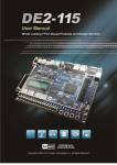
We want to design a modulo-10 counter-like circuit that behaves as follows. It is reset to 0 by the Reset input. It
has two inputs, w1 and w0 , which control its counting operation. If w1 w0 = 00, the count remains the same. If
w1 w0 = 01, the count is incremented by 1. If w1 w0 = 10, the count is incremented by 2. If w1 w0 = 11, the
count is decremented by 1. All changes take place on the active edge of a Clock input. Use toggle switches SW2
and SW1 for inputs w1 and w0 . Use toggle switch SW0 as an active-low synchronous reset, and use the pushbutton
KEY0 as a manual clock. Display the decimal contents of the counter on the 7-segment display HEX0.
1. Create a new project which will be used to implement the circuit on the DE2 board.
2. Write a VHDL file that defines the circuit. Use the style of code indicated in Figure 3 for your FSM.
3. Include the VHDL file in your project and compile the circuit.
4. Simulate the behavior of your circuit.
5. Assign the pins on the FPGA to connect to the switches and the 7-segment display.
6. Recompile the circuit and download it into the FPGA chip.
7. Test the functionality of your design by applying some inputs and observing the output display.
Part V
For this part you are to design a circuit for the DE2 board that scrolls the word "HELLO" in ticker-tape fashion on
the eight 7-segment displays HEX7 − 0. The letters should move from right to left each time you apply a manual
clock pulse to the circuit. After the word "HELLO" scrolls off the left side of the displays it then starts again on
the right side.
Design your circuit by using eight 7-bit registers connected in a queue-like fashion, such that the outputs of the
first register feed the inputs of the second, the second feeds the third, and so on. This type of connection between
registers is often called a pipeline. Each register’s outputs should directly drive the seven segments of one display.
You are to design a finite state machine that controls the pipeline in two ways:
1. For the first eight clock pulses after the system is reset, the FSM inserts the correct characters (H,E,L,L,0, , , )
into the first of the 7-bit registers in the pipeline.
2. After step 1 is complete, the FSM configures the pipeline into a loop that connects the last register back to
the first one, so that the letters continue to scroll indefinitely.
Write VHDL code for the ticker-tape circuit and create a Quartus II project for your design. Use KEY0 on the DE2
board to clock the FSM and pipeline registers and use SW0 as a synchronous active-low reset input. Write VHDL
code in the style shown in Figure 3 for your finite state machine.
Compile your VHDL code, download it onto the DE2 board and test the circuit.
Part VI
For this part you are to modify your circuit from Part V so that it no longer requires manually-applied clock pulses.
Your circuit should scroll the word "HELLO" such that the letters move from right to left in intervals of about one
second. Scrolling should continue indefinitely; after the word "HELLO" scrolls off the left side of the displays it
should start again on the right side.
Write VHDL code for the ticker-tape circuit and create a Quartus II project for your design. Use the 50-MHz clock
signal, CLOCK_50, on the DE2 board to clock the FSM and pipeline registers and use KEY0 as a synchronous
active-low reset input. Write VHDL code in the style shown in Figure 3 for your finite state machine, and ensure
that all flip-flops in your circuit are clocked directly by the CLOCK_50 input. Do not derive or use any other clock
signals in your circuit.
Compile your VHDL code, download it onto the DE2 board and test the circuit.
6