1
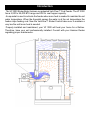
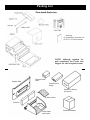
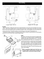
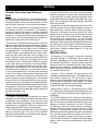
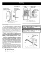
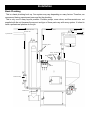
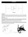
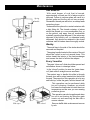
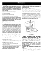
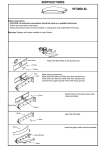
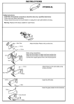
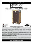
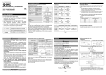
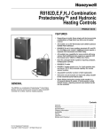
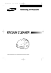
Installation & Operating Manual
VF3000 Coal Stoker Boiler
R9
SAFETY NOTICE
Please read this entire manual before you install and use your new room heater. Failure
to follow instructions may result in property damage, bodily injury, or even death.
FOR USE IN THE U.S. only. NOT SUITABLE FOR INSTALLATION IN MOBILE HOMES
IF THIS boiler IS NOT PROPERLY INSTALLED, A HOUSE FIRE MAY RESULT. FOR YOUR SAFETY, FOLLOW INSTALLATION DIRECTIONS. INSTalLATION should be performed by a qualified installer.
CONTACT LOCAL BUILDING OR FIRE OFFICIALS ABOUT RESTRICTIONS AND INSTALLATION INSPECTION
REQUIREMENTS IN YOUR AREA.
Contact your local authority (such as municipal building department, fire department, fire
prevention bureau, etc.) to determine the need for a permit.
this appliance is also approved for installation into a shop.
save these instructions.
# 3-90-70741
3
Index
Introduction
4
Specifications
5
Hot Water Coil
5
Warnings
6
Packing List
7
Assembly
8
Venting
11
Installation
14
Verti-Flow™ Stoker Control
17
Operation
19
Feed Adjustment
19
Maintenance
20
Troubleshooting
22
Aquastat Installation
23
Wiring Diagram
25
Service Parts
26
Warranty
29
4
Introduction
The VF 3000 Stoker Boiler features our patented Verti-Flow™ Coal Feeder. The VF 3000
has a 5,000 to 95,000 BTU range and 250 lb. coal hopper capacity.
An aquastat is used to activate the feeder when more heat is needed to maintain the set
water temperature. When the Aquastat senses the water is at the set temperature the
feeder stops feeding coal. Now the Verti-flow™ Stoker Control takes over to maintain a
very low fire until more heat is needed.
Properly installed and maintained, your VF 3000 will heat your home for a lifetime.
Therefore, have your unit professionally installed. Consult with your Harman Dealer
regarding proper maintenence.
5
Specifications/Hot Water Coil
Hot Water Coil
To install a hot water coil:
1. Remove the blank plate covering the water coil opening.
2. Insert the coil into the boiler as shown. Be sure to put a new gasket around the coil plate.
3. Tighten all bolts evenly.
4. Fill the boiler and check for leaks before and after the boiler is up to temperature. Rust caused by a
leak can reduce the life of the boiler.
5. A tempering valve may be installed between the in and out pipes to reduce the maximum water
temperature at the tap.
NOTE: This hot water coil is rated at 4 gallons per minute.
6
Warnings
Never sleep in the same room with any coal burning stove.
Always empty the hopper when not burning for more than a week. When left standing for long
periods with wet coal, the pusher block will rust and corrode, causing it to seize. If the stoker is
then turned “on”, damage to the pusher assembly and feed motor will result. This will be considered
neglect and will void the warranty on those parts. Always check to see if moving parts are free
before using if the unit has not been burned for a period of time. This can best be determined by
shaking the adjuster rod.
Freshly delivered coal is typically watered down to minimize dust when loading and unloading.
Wet rice coal does not flow as well as damp or dry coal, and may bind or bridge in the hopper. We
do not recommend loading your hopper with wet coal. If you must burn wet coal, the feed rate will
likely need increased, in order to get the same size fire. As the wet coal in the hopper dries out, the
feed rate will need decreased to avoid over-feeding. Using wet coal, in an emergency, will likely
not damage your stove as long as it is hot and burning at the time. The damage is caused when
the hopper has wet coal in it when the stove is cold. This will cause rust and corrosion which is
considered neglect and will not be covered by the product warranty.
Appliance Placement: The VF3000 must be installed on a non-combustible floor. The noncombustible floor must also extend a minimum of 18” in front of the firebox door, and 8” to the
sides. Maintain a minimum of 18” of clearance to combustible walls, 24” to the ceiling and keep
combustible materials a minimum of 36” away from in front of the appliance.
This boiler may be connected to an existing boiler heating system. Inter-connection may be done in a
series or parallel configuration. Consult with your licensed plumber or HVAC professional to determine
the most effective installation for your heating needs.
This unit must be connected to a chimney capable of providing a -.04 minimum draft.WARNING:
If the chimney has no draft, coal gases may escape from the unit and stove pipe. These gases are
toxic and can be fatal. It is recommended that a CO detector be installed to warn of this condition.
7
Packing List
NOTE: Although required for
unit completion, the Feeder and
Hopper are sold as separate items.
Adapter Plate
Pressure Relief
Valve
Temp/Pressure
Gauge
Aquastat-(3 Pieces)
and Sensor
(2) Grate Inserts
Firebricks
Grate Holder
with Gasket
Combustion Blower
8
Assembly
Top
Left Side
Hopper
Support
Front
Door
Blank
Boiler
Hopper - Sold
separately
Cleaning Rod
Spring Handle
Adapter
Plate
Right Side
Baffle
Clean out slide
Base Jacket
Flue Pipe
Base
Ash Tub
Flue Plate
The VF3000 is reversible as to which end the
hopper and flue pipe are located. Therefore, a
decision must be made as to which way will work
best for your situation.
If you woud like to have the flue to the right and
the hopper to the left, make sure the gaskets are in
place on both the flue pipe and flue plate. Bolt the
flue pipe on the right end and the flue plate on the
left end of the base. Next, the baffle must be slid
into place on the right end with the center of the
base. Note the baffle and flue pipe must always be
at the same end and opposite the hopper.
Next, place the base jacket around the base and
clamp into place with the four clamping bolts on
the front of the base. The hole in the jacket goes
around the flue pipe.
Ash Door
Place 1/4” x 1” gasket around the flat edge on
top of the base. Now place the boiler on top of
the base with the feeder opening opposite the
flue pipe. Place 1/4” x 1” gasket around the door
openings on the boiler. Bolt the door mount on the
front door opening with 5/16” x 1” flat head bolts.
Bolt the door blank on the rear opening with 5/16”
x 1” hex head bolts.
Now the outer jacket can be installed. The front
jacket with the coil hole must be installed first. Next,
the two sides which hold the front in place and then
the top which holds the sides in place.
9
Assembly
Hopper right, flue left
Hopper left, flue right
Feeder
Begin assembly by sliding the pusher block with the adjuster rod from the front through the slot shown
in Fig. 1. Be sure the pusher block is turned with the bolt hole to feed indicator side. Next, hold pusher
block in the most rearward position and slide the adjuster tube over the adjuster rod until it bottoms out
on the pusher block. Thread the adjuster, then the wing nut on the end of the adjuster rod.
Put gasket around the opening on the adapter plate. Slide the feeder through the plate and bolt together
with two 5/16 x 3/4” bolts. Next, install the grate holder.
Fig. 1
Grate
The grate is composed of four pieces: the grate holder,
(2) grate inserts, and firebrick angle. The firebrick angle
is bolted to the grate holder with (2) 3/8” x 1 1/4” bolts.
Before installing the grate holder, 3/8” round gasket must
be checked in the groove on the bottom side of the grate
holder, as shown in fig. 4. Check to be sure the gasket
has not been damaged. Locate the flange at the rear
of the grate holder into the slot on the feeder as shown
at left. Bolt the front end down snug with the 1/4” x 20
allen bolt and nut provided. The rear end will be locked
in place by the flange.
Before completely tightening the bolt, be sure
the grate holder is back as far as possible and
centered side to side on the feeder opening.
Fig. 2
10
Assembly
Fig. 4
Fig. 3
Snug these bolts only.
Grates and Firebrick
Lay the two grate inserts into the grate holder as shown.
Divide the spaces between the grates equally and be sure
they are not tight. The spaces are needed for expansion.
The grate inserts can also be installed or removed after
the feeder is in place.
Place the two firebricks on the grate angle and make
the two bolts snug on the adapter plate as shown.
Apply 1 inch flat gasket around the feeder opening and
insert the feeder and adapter plate into the boiler and
tighten. NOTE: You will need a 3/4” socket to do this.
Blower
Remove one of the screws on the intake screen, and
install the blower restrictor plate. Install the blower on
the bottom of the feeder by sliding it into the bracket as
far as it will go. NOTE: The bolt holes on the blower
flange are not used.
Control Box
Install the control box on mounting pad provided on the
side of the stoker with (4) #8-32 bolts and nuts.
Plug the gear motor into the top receptacle, and the
combustion blower into the middle receptacle on the
control box. The bottom receptacle is not used.
Hopper
Insert small end of hopper into the hopper slot on the
feeder. Push top of hopper under the hopper support,
causing the slot on the bottom side of the support to
hook onto the hopper. The hopper support will spring up
slightly for the hopper to go under. If you have difficulty
getting the hopper under, you can raise the top slightly
The feed motor cover can now be installed.
11
Venting
Chimney Connectors and Chimneys
Draft
Draft is widely misunderstood. It is important that you,
the stove operator, realize that draft is a variable effect,
not a given quantity. Stoves and chimneys do not have
draft, yet draft is the key to your stove’s performance.
Draft is a force, produced by an operating stove and
the chimney to which it is attached. It is created by
hot gases rising up the chimney, creating a pressure
difference between the inside of your home and the
outside air. It continually moves fresh combustion air
into the stove, and hot exhaust gases out of the stove;
without this constant flow, the fire will go out.
Other factors, such as barometric pressure, winds, the
tightness of the home, the total inside chimney volume,
chimney height and the presence of venting devices
such as exhaust fans also play a role in maintaining
an adequate draft. Low barometric pressures, super
insulated homes, and exhaust fans can reduce draft;
winds can play havoc with draft; and too large or too
small a chimney volume can cause reduced draft due
to the excessive cooling or not enough room to vent
the exhaust gases. Introducing outside air directly
to the stove may help remedy a low draft problem.
Some signs of inadequate draft are smoking, odor,
difficulty in maintaining the fire, and low heat output.
Overdraft can be caused by a very tall chimney even if
it is the recommended size, and can cause overfiring
of your stove. Signs of an overdraft include rapid fuel
consumption, inability to slow the fire, and parts of the
stove or chimney connector glowing red. It is important
that you follow the chimney guidelines in this manual,
including size, type, and height to avoid draft problems.
When installed and operated according to this manual,
the appliance will produce enough hot gases to keep
the chimney warm so that adequate draft is maintained
throughout the burn cycle.
Chimney Connectors
In general, following these guidelines will ensure
compliance with all national and provincial codes; prior
to beginning your installation, check with your local
building code official(s) regarding any additional local
requirements or regulations which may influence the
design and placement of your venting system.
The VF3000 may be installed with (.6 mm) 24 gauge
chimney connector pipe. The size of the connector
should correspond to the size of the flue collar opening.
Do not use makeshift components.
No part of the chimney connector may pass through
an attic or roof space, closet or other concealed space,
or through a floor or ceiling. Whenever possible, avoid
passing the connector through a combustible wall; if you
must, use an approved wall pass-through, described
later in this section.
Assemble the connector beginning at the flue collar,
with the crimped ends pointing towards the stove (to
keep debris and creosote flakes inside the system).
Each joint, including the one to the stove’s flue collar
and the one to the chimney itself should be secured
with at least three sheet metal screws. Screws may
be a maximum of 3 inches apart. A 1-1/4" (32 mm)
overlap is required at each joint, including the flue collar
attachment. No more than two 90 degree elbows should
be used, and the total length of connector should not
exceed 10 feet (3m) All horizontal runs of connector
must have a minimum upward slope of 1/4" per foot
(20 mm per meter).
Wall Pass-thrus
Occasionally it is necessary to pass the chimney
connector through a combustible wall to reach the
chimney. Depending on your local building codes, and
the pertinent provincial or national codes, there are
several choices for accomplishing this safely. Before
beginning your installation, contact local officials, and
also the chimney connector and chimney manufacturer
for specific requirements.
Canada. Three methods are approved by the
Canadian Standards Association. The diagram shows
one method requiring an 18” (460 mm) air space
between the connector and the wall. It allows use of one
or two covers as described in the diagram. The other
two methods are described in detail in the current issue
of CAN/CSA B365, the national standard.
United States In the U.S., the national code is NFPA
211. While many localities adopt this standard, be sure
to check with local authorities before beginning your
installation.
The NFPA (National Fire Protection Association)
permits four methods for passing through a combustible
wall. A commonly used method to pass through a wall
directly to a masonry chimney is to clear a minimum
12”(305 mm) around the entire chimney connector,
and fill it with brick masonry which is at least 3.5”(90
mm) thick. A fireclay liner, minimum 3/8” (9 mm) wall
thickness must run through the brick wall to the chimney
liner (but not beyond the inner surface of the liner). It
must be cemented in place with refractory cement.
This method is illustrated. For details on the other three
options, refer to the most recent edition of the NFPA
211 code.
12
Venting
Closest
Combustible Material
Minimum 2" (50mm)
Clearance to Brick
Liner
Chimney Flue
Hole with a minimum
clearance of 18" (450 mm)
between connector and
wall.
Non-combustible cover,
one side only. If two
covers are used, each
must be mounted on
non-combustible spacers
at least 7/8" (21mm) away
from the wall.
Minimum 12"
(300mm) to Brick
Fire Clay
Thimble
Chimney
Connector
Masonry Chimney Built to
NFPA 211 Specifications.
1" (25mm)
Clearance
Minimum 12" (300mm)
to Combustibles
AN APPROVED U.S.
WALL PASS-THROUGH
AN APPROVED CANADIAN WALL
PASS-THROUGH
The Chimney
This unit must be installed into a chimney approved
for use with solid-fuel appliances. In the U.S., it must
be connected to (1) a prefabricated chimney complying
with the requirements for Type HT chimneys in the
Standard for Chimneys, Factory-Built, Residential Type
and Building Heating Appliances, UL 103, or (2) a codeapproved masonry chimney with a flue liner.
In Canada, this unit is listed for use with prefabricated
chimneys tested and listed to the high temperature (650
degrees C) chimney standard, ULC S-629, or with a
code approved masonry chimney.
The minimum recommended height for any chimney
is 16 ft (4.8 m) above flue collar height. A round flue
(either masonry or approved prefabricated), of either 6"
(150 mm), 7" (180 mm) or 8" (200 mm) may be used.
For square or rectangular masonry chimneys, nominal
sizes of 8" x 8" or 8"x 12" (200mm x 200 mm, 200 mm
x 300 mm) may be used.
Codes require that solid-fuel chimneys extend 3 ft (0.9
m) above the highest point at which they exit from the
roof. Then, the chimney must extend 2 ft.(6 m) above
the highest point within a 10 ft (3 m) radius. Thus, the
3 foot, 2 foot, 10 foot rule:
3ft. - Above roof exit point
2ft. - Higher than anything within-
10ft. of the chimney.
Do not connect this unit to a chimney flue
servicing another appliance.
This VF3000 Is Approved To Burn
Anthracite “Rice” Coal Only.
More Than 10 ft. (3m)
10 ft. (3m)
2 ft. (0.6m) min.
Ridge
Height Necessary
Above Any Roof
Surface Within 10ft.
(3m)
3ft. (0.9m)
minimum
above
exit
point
Chimney
The 3-foot, 2-foot, 10 foot rule
13
Venting
Existing Masonry Chimneys
If you plan on using a pre-existing masonry chimney,
have it thoroughly inspected and cleaned. Any faults
which make the chimney unsafe and unusable must
be repaired prior to use. These can include improper
height, structural defects, blockages, inadequate
clearance to combustibles, unsealed openings into
other rooms of the house, signs of creosote or smoke
leakage, a loose or absent clean-out door, or absence
of a liner.
Venting to a Masonry Chimney
When connecting to a masonry chimney, several
provisions are standard. First, whether the chimney
connector is vented to the chimney through a thimble
or a breech pipe, neither must pass beyond the inner
surface of the chimney liner, and both must be firmly
cemented in place with refractory cement. (A thimble is
a masonry pipe which is inserted through the chimney
wall, and is frequently the preferred method; a breech
pipe is a piece of steel pipe used the same way.) In
Canada, a breech pipe has ridges or protrusions to lock
it firmly into the refractory cement. In either case, the
chimney connector vents to the chimney through the
thimble or breech pipe.
Using a thimble, the connector slides completely
inside the masonry to the inner edge of the flue liner,
and may be easily removed for chimney and connector
inspection. A breech pipe must extend at least 2" (50
mm) into the room, so the connector can be attached
with sheetmetal screws.
Venting to a Masonry Fireplace Chimney
In some situations, a code compliant chimney originally
used for a masonry fireplace may be used to install
your stove. In addition to the requirements found in the
previous paragraphs, it is important to be aware that
all clearances must be met, including those from the
chimney connector to combustibles. Do not forget to
include floor protection in your plans. (See Clearances
and Floor Protection in this section.) Since many
fireplaces have exposed wooden mantels and trim,
pay special attention to the clearances necessary to
these materials.
If your fireplace chimney is behind a combustible wall,
you must use an approved wall pass-through system
to gain access to the masonry chimney. The chimney
connector must enter the chimney at a place where it is
lined, and the fireplace must be made inoperable. For
example, you might remove the damper, replacing it with
a secure, airtight, noncombustible seal (removable for
inspection); this also satisfies the requirement that no
room air must be allowed to enter the chimney.
Do not burn any fuel other than coal. Never use highly
volatile substances in your stove, such as gasoline,
which could cause an explosion.
When solid fuels are burned completely, they produce
water and carbon dioxide. However, in long slow
burns, a substantial amount of carbon monoxide may
be produced. If allowed to build up, carbon monoxide
(which is odorless) can prove fatally poisonous. Proper
ventilation and draft will prevent this from happening.
If you smell smoke, thoroughly ventilate your dwelling.
Contact your dealer to arrange for a draft test.
Other causes of poor ventilation or draft are icing,
exhaust fans, a blocked outside air inlet, and room
air starvation. If your stove is sluggish and you get
occasional odor, check these possibilities and increase
the air flow in your home.
Installing to a Prefabricated Chimney
When venting your stove using a prefabricated
chimney, be sure to contact local building code
authorities, and to follow the manufacturer’s instructions
exactly. Use only the manufacturer’s parts; do not use
makeshift installation techniques. All prefabricated
chimneys must be tested to either the U.S. or Canadian
high-temperature standards, UL 103 or ULC S629.
Do not connect the venting to any air
distribution duct or system
14
Installation
Aquastat and Wiring
See page 23 for assembly and mounting details. Pay close attention to the jumper positioning inside
the A350 and S350 controls. Also note the sensor and its wire length when considering the mounting
location. Remember that 212° f. is boiling temperature and must be avoided. Be sure to incorporate a
means for flowing water in the event of an over-heat condition. Coal can not just stop burning when there
is no demand for heat. Never fire a boiler with no water in the system. Serious consequences will result.
15
Installation
Basic Plumbing
This is a basic plumbing hook up. Your system may vary depending on many factors. Therefore, we
recommend having experienced personnel do the plumbing.
This is only one of many layouts possible. Cirulator pumps, zone valves, and thermostats are not
supplied with the unit because the amount and type of these parts vary with every system. It is best to
have a professional plumber do the job.
Fresh water in- with
automatic fill
Heated domestic water
Air Scoop
System Return
System Supply
Tempering Valve
Expansion Tank
Temp. / Pressure Gauge
Aqua Sensor Well
Pressure Relief
Aquastat
Circulator Pump
Boiler Drain
16
Installation
Clearances
Installation
Place the boiler a minimum of 18” from a wall. The flue pipe must be at least 18” from anything
combustible. The rear of the hopper should be a minimum of 36” from the wall. The boiler should be
placed on a non-combustible floor. Secure all chimney connector pipe joints with a minimum of 3 sheet
metal screws.
Draft Test Procedure
Attach a draft meter to the vent pipe on the boiler side of the barometric damper (if installed). With a
fire established, the chimney draft should be between -.04 and -.06 inches of Water Column. If the flue
draft exceeds these readings, install and adjust the barometric damper accordingly.
DO NOT operate if the flue draft exceeds -.10 inches Water Column ( -24.9 Pa).
Next, remove the allen head set screw from the center of the firebox door and attach your draft meter.
The firebox draft should be -.04 to -.05 in W.C. Adjust the combustion blower restrictor plate, closed to
increase the draft or open to decrease firebox draft.
Combustion Blower
Restrictor Plate
17
Verti-Flow™ Stoker Control
0.75 A
MAX LOAD
1.25 A
MAX LOAD
COMPONENT RECEPTACLES - ON SIDE
0.5 A
MAX LOAD
VERTI - FLOW ™
STOKER CONTROL
Verti-Flow™ Stoker Control
This section describes the features and operations of the Harman VertiFlow™ Stoker Control. The timers are adjustable from 0 minutes to 15
minutes in 1 minute steps. There are red lights on the front panel to show
proper operation of the timer. One indicator shows power is applied to
the unit. The other three indicators show when power is available at the
adjacent receptacle.
The stoker control will be mounted on the side panel of the feeder
directly below the coal hopper. The three receptacles and switch will be
facing forward while the power cord, 3 AMP fuse access port and the
thermostat connections will be to the rear.
18
Verti-Flow™ Stoker Control
The Verti-Flow™ Stoker Control
The top receptacle (0.5 A) provides power to
the coal feeder motor. Thus, the plug from the
coal feeder motor should be inserted into this
receptacle.
The center receptacle (0.75 A) provides power
for the combustion blower motor. Thus, the plug
from the combustion blower should be inserted
into this receptacle. The bottom receptacle (1.25
A) is not used.
The thermostat connections on the back panel of
the stoker control are .25 inch male quick connect
terminals. The mating connectors (supplied) should
be .25 inch female quick connector terminals. The
wire should be no smaller than 22 gauge.
The thermostat connections should be connected
to the aquastat as shown on the wiring diagram.
The AC power cord should be the last connection
made. The power cord should be plugged into a
115 VAC / 60 hertz wall outlet, which has proper
grounding available. This 115 AC volt wall outlet
should also be capable of handling 3 amps of
current because this is the maximum amperage
this unit will draw.
How to operate the Stoker Control
There are four operator interfaces on the Stoker
Control. The operator interfaces are: one (1) rocker
switch and three (3) 16-position rotary switches.
The rocker switch is a power switch that controls
only the coal feeder motor. For normal operation
this switch should be placed in the “on” position.
This switch’s operation can be verified by a small
red light above the coal feeder receptacle being
on when the switch is on. The off position is used
for lighting the fire.
The other three switches are the customer’s
adjustments for the timers (on timer, off time,
distribution blower time). These switches can
adjust each timer individually from 1 minute to 15
minutes in 1 minute increments. Do not set pilot
mode timers to 0.
The “on” time and the “off’ time should be
programmed to a minimum time that keeps the coal
burning during the maintenance cycling mode. The
distribution blower time should be set to 0. This is
because the VF 3000 doesn’t have a distribution
blower. The Verti-Flow™ Stoker Control is also
used on the Magnum Stoker which does use this
timer.
Recommended timer settings to start are: “on” 4
minutes, “off” 12 minutes, extend timer 0 minutes.
You may find that these settings produce too much
heat in pilot mode. If so, you can reduce the “on”
time and increase the “off” time. However, we do
not recommend going below 4 minutes with the on
time for efficiency reasons.
DANGER- Risk of Fire or Explosion;
DO NOT burn garbage, gasoline, drain
oil or other flammable liquids.
CAUTION- Hot While in Operation;
- Keep Children Away
- Do Not Touch
19
Operation
Fill the boiler and plumbing system
with water prior to lighting!
Starting a fire
Feed Indicator
Fill the hopper with rice coal. With the aquastat
calling for heat, the coal will begin to feed onto
the grate inside the stove. This process can be
accelerated by adjusting the feed rate to the
maximum position. When the coal starts to come
up out of the grate and is almost up to the area
where the holes start, turn the feed adjuster back
about 2 turns and turn off the feed motor with the
switch on the side of the control box. Whether using
wood pellets, charcoal, or kindling and paper, mix
your starter material with the coal on the grates,
for best results. Use a match to light the fire or
starting material.
After the coal is burning, the feed motor can be
turned on and the coal fire will continue to get
larger. Fresh coal will continue to be pushed onto
the grate and ashes will be pushed off the grate.
The feed rate must be adjusted so the coal is
burned up and turned to ashes before the coal gets
to within one inch of the end of the grate. Too high
of a feed rate will push unburned coal off the coal
grate, therefore wasting fuel.
Feed Adjustment
The feed indicator on the side of the feeder shows
how far the pusher moves each stroke. There
are dots above the indicator spaced 1/8” apart. A
movement of one dot would give a low burn, two
dots medium and three dots high. Lock the adjuster
with the wing nut after adjusting feed rate.
After the fire is burning and the feed rate is
adjusted, you can now set the aquastat to the
desired water temperature.
20
Maintenance
Ash Removal
Spring
handle
With each hopper of coal that is burned,
approximately one ash pan full of ashes must be
removed. Failure to remove ashes will result in a
blocked grate and the fire will not burn properly.
Remember, the ash pan will be hot, so always wear
protective gloves.
Ashes should be placed in a metal container with
a tight fitting lid. The closed container of ashes
should be placed on a non-combustible floor or
on the ground, well away from all combustible
materials, pending final disposal. If the ashes are
disposed of by burial in soil, or otherwise locally
dispersed, they should be retained in the closed
container until all cinders have thoroughly cooled.
Weekly:
The small tray in the side of the stoker should be
removed and emptied.
The spring handle located at the center of the unit
should be cycled in and out several times. This
action cleans the interior of the heat exchanger
and causes the dust to fall into the ashpan.
Every 3 months:
The grate “clean-out” slide should be opened and
reclosed as shown in drawings below.
In the “closed” position, be sure the “grate cleanout” plate slide is straight across as shown.
Baffle slide
The easiest way to handle this slide is through
the ash door with a poker inserted into the hole at
the end. The purpose of this operation is to let any
ash build-up, under the grate, fall into the ash tub.
This operation can be performed while
the unit is burning. However, you should
first lower the thermostat to lower the stove
temperature and be sure you are wearing
protective gloves.
Slide open
The operation can also be performed when
the unit is not burning by lifting the grate
inserts out and removing the ash with a
vacuum cleaner.
Slide closed
Remove baffle slide as shown and remove
fly ash.
21
Maintenance
Annually:
The end of the heating season is the best time to
perform annual maintenance. Rust and corrosion
can form much faster in the high humidity of
summer, so cleaning your VF 3000 will prevent
those damages.
1. Remove all coal from the hopper
2. Remove all ashes
3. Remove and clean flue pipe
4. Check chimney and clean if necessary
5. Remove hopper and check for rust at bottom
edges. If rust is found, remove it with a file or
sandpaper then paint the area with spray paint
available at your Harman dealer.
Hopper Maintenance:
Always empty the hopper when not burning for
more than a week.
Pusher Block Maintenance:
When left standing for long periods with wet coal,
the pusher block will rust and corrode, causing it
to stop. If the stoker is then turned “on”, damage
to the pusher assembly and feed motor will result.
This will be considered neglect and will void the
warranty on those parts. If the unit has not been
burned for a period of time, always check to see if
moving parts are free before using. This can best
be determined by shaking the adjuster rod.
6. Check the feeder for rust and corrosion where
the hopper fits into it.
7. Check pusher block to be sure it moves freely.
This can best be done by shaking the adjuster rod.
If it does not move freely, it should be removed
and cleaned. Also remove any rust or corrosion
from the area where the pusher block slides and
spray with WD-40 or other rust preventing spray.
To remove pusher block, remove cover, wing nut,
adjuster and adjuster tube. Remove motor mount
with motor in place and cord still attached. Swing
pusher assembly up as high as it will go. Remove
feed indicator from side with allen wrench. Now
the pusher block can be removed. To reinstall, just
reverse procedure. If the pusher block cannot be
removed, call your Harman dealer.
WARNING- Risk Of Fire;
- DO NOT Operate with flue draft exceeding -.10
in Water Column (-24.9 Pa.)
- DO NOT operate with fuel loading or ash
removal doors open.
- DO NOT store fuel or other combustiblematerial
within specified installation clearance areas.
- INSPECT and clean chimney flue system
and chimney connectors regularly.
Adjuster Rod
CAUTION:
- Inspect flue pipes, joints, and seals
regularly to ensure that smoke and flue
gases are not drawing into the dwelling.
- Cleaning of the heat exchanger, flue
pipe, chimney, and draft inducer if used,
is especially important at the end of the
heating season to minimize corrosion
during the summer months caused by
accumulated ash.
- DO NOT use chemicals or fluids to start
a fire.
- DO NOT burn garbage, gasoline, naptha,
engine oil, or other inappropriate materials.
22
Troubleshooting
Feeding Problems
Gas Odor Problems
Wet Coal:
Wet coal does not flow the same as dry coal,
therefore; the feed rate will change with wet coal.
If it is too wet, it may not feed at all. Wet coal can
also cause a sulfur odor.
Gas Alarm Goes Off or Sulfur Odor Exists:
A sulfur smell may be noticed when a door is
opened during operation with wet or damp coal.
This is normal. However, it is not recommended
that wet coal be used or the doors be opened for
more than a few seconds while burning to inspect
the fire or remove ashes.
Wrong Size Coal:
The Verti-Flow™ System is designed to burn rice
coal (or buckwheat coal if rice is not available). If
buckwheat coal is burned, raise the draft setting
from .04 to .06. Larger coal will not feed or burn
properly.
Hopper Blocked:
Sometimes wood, paper, or other foreign objects
accidently end up in your coal bin and can slow
down or block the flow of coal. You may have to
empty the hopper to find the blockage.
Pusher Out of Adjustment:
This can happen when more than one person tend
the stoker. One person does not tell the others what
adjustments were made.
Lack of Draft or a Down Draft in the chimney:
These will cause gases to escape from the unit.
No unit will function properly without draft. Any draft
problem should be corrected before use.
A draft inducer may be installed to increase draft
in marginal situations. The installation should be
performed by your dealer who is factory trained to
correct any problems on initial start up. After proper
installation, many years of trouble-free operation
can be expected.
Stoker Control Troubleshooting
Problem: No motors or lights will turn on.
Solution:
1. Check AC power cord to the stoker control
2. Check the 3 amp fuse on the side panel of the
stoker timer. (replace only with a 3 amp 3 ag slow
blow fuse.)
Problem: Lights on the stoker control are on, but
motors will not operate.
Solution: Check the AC power plugs from the
motors (are they securely plugged into the correct
outlet?)
Problem: One of the motors will not operate.
Solution: Check if the light above the receptacle is
lit. Check the AC power plug from the motor (is it
securely plugged into the correct outlet?”
Problem: The motors are cycling on and off, but
not in the correct order.
Solution: Check the AC power plugs from the
motors (are they securely plugged into the correct
outlet?)
Problem: Coal feeder motor will not turn on.
Solution: Check if the red light is lit, if not, check if
the feeder motor switch is turned on.
Problem: The motors turn on and off as
programmed, but the water temperature is below
the thermostat setting.
Solution: Check the connections from the stoker
control to the aquastat.
23
AQUASTAT INSTALLATION
AQUASTAT INSTALLATION
(a350My350, s350)
1. Lay the din rail on a flat surface with the flat side down. Secure one end clamp on the left side.
2. From the right side, slide the A350 control onto the din rail. Slide the control to the left until it is against
the end clamp.
3. Repeat Step 2 with the Y350 power module, connecting it to the A350 control. NOTE: Be careful when
fastening the plug-together connecters located at the top of the controls.
4. Repeat Step 3 with the S-350 control, connecting it to the Y350 power module.
5. Install the other end clamp to the right side of the din rail.
6. Remove the covers on the three controls by using the four screws on each control. (A350, Y350, S350)
7. Install the terminal box to the controls by using the three chase nipples and locknuts supplied with
the kit.
8. Mount the terminal box with controls to the boiler jacket or any other desired location by the four holes
in the terminal box.
9. Using two 8-32 nuts, install the terminal block over the studs located in the terminal box.
10. A350 Control: 1) Set the jumpers to the heat position. They may already be in this position. 2) Set
the differential to the desired set point. 3) Terminate the wires using the common and the normally
open terminals.
11. Y350 Control: 1) Terminate the power wiring using the 120 VAC terminals on the control. This will
be supplied from the terminal block located in the terminal box.
12. S350 Control: 1) Set the offset to the desired set point. 2) Set the differential to the desired set
point. 3) Set the jumpers to the cooling position. 4) Terminate the wiring using the common and the
normally open terminals.
13. Set the A350 control to the desired water temperature.
14. After locating and installing the sensor well and sensor, wire the sensor to the A350 control. The
terminals marked “sen” and “com” are located in the upper left-hand corner of the A350 control.
Make sure the sensor is inserted into the well fully and secured with a setscrew.
15. Reinstall the covers on the three controls
16. NOTE: Sensor wire can be lengthened up to 50 feet with standard 22 awg t-stat wire. Shielded cable
is generally not required for sensor wiring runs of less than 50 feet. However, if over 50 feet, follow
this guide:
WIRE GAUGE/SHIELDED CABLE LENGTH
14 awg.....................800 feet
16 awg.....................500 feet
18 awg.....................310 feet
20 awg.....................200 feet
22 awg.....................124 feet
24
AQUASTAT
25
Wiring Diagram & Fuel
Coal
Approved For Use With Anthracite Rice Coal Only.
Anthracite coal is “hard coal”, mined primarily in the northeast United States. Rice coal, as shown at
right, is typically described as coal having no dimension larger than 3/8”. Other size coal may cause
feeding problems, and is therefore not recommended for use in your VF3000.
It is best to buy your supply of coal when the temperature is above freezing. This is because many
dealers put kerosene or fuel oil on the truck box and calcium on the coal to keep it from freezing while it
is being transported. The calcium can promote rust and the oil may cause an odor depending on what
type is used.
It is best and most convenient to have a coal bin inside and close to the boiler. The bin should have
drainage to allow the water to drain.
DO NOT store fuel within the specified clearance area.
Rice Coal
VF3000
Service Parts
Beginning Manufacturing date: n/a
ending Manufacturing date: active
Coal Stoker Boiler
1-70-03241
1
3
2
IMPORTANT: THIS IS DATED INFORMATION. When requesting service or replacement
parts for your appliance please provide model number and serial number. All parts listed
in this manual may be ordered from an authorized dealer.
IteM
deSCrIPtIOn
COMMentS
Stocked
at depot
Part nuMBer
1
Hopper assembly
1-00-4677373
2
Timer control box
3-20-44322
Y
3-20-00900
Y
Qty 2 req
4-00-00042
Y
Spring handle - brass plate 1/2”
Pkg of 3
3-40-00086-3-3
Door Latch
4 Sets
1-00-00036
Fuse holder - (timer control box)
3
Door handle
Y
Additional service part numbers appear on following page.
07/12
VF3000
Service Parts
Beginning Manufacturing date: n/a
ending Manufacturing date: active
#4 Feeder assembly
4.18
4.1
4.20
4.19
4.16
4.17
4.14
4.15
4.3
4.2
4.13
4.4
4.5
4.6
4.12
4.7
4.8
4.9
4.10
4.11
IMPORTANT: THIS IS DATED INFORMATION. When requesting service or replacement parts for
your appliance please provide model number and serial number. All parts listed in this manual may
be ordered from an authorized dealer.
IteM
4.1
deSCrIPtIOn
COMMentS
Part nuMBer
Feeder Motor Cover
2-00-00052P
Pusher Block Assembly (w/Tube & Threaded Rod)
1-10-00099
Stocked
at depot
Y
4.2
Pusher Block Adjuster Tube
4.3
5/16-18 Zinc Plated Cold Forged Wing Nut
Pkg of 25
3-30-8012-25
1-10-00050P
Y
4.4
Pusher Block Adjuster Rod
Pkg of 2
2-00-08011-2
Y
4.5
Pusher Block
3-50-00026
Y
4.6
Cam Block Assembly
1-10-00102A
Y
Feeder cam block
3-50-00054
Y
Feeder cam Bearing
3-31-3014
Y
4.7
Cam Arm cover
2-00-00053P
Y
4.8
Fines Tray
2-00-00055
Y
4.9
Feed Indicator Hardware
1-00-00056
Y
4.10
Feeder Body Weldment
1-10-00687
Y
4.11
Clean-Out Slide
2-00-00048P
Y
4.12
Gasket 1” White w/Adhesive (Feeder Gasket)
1-00-88100
Y
1-10-01000
Y
4-00-00046D
Y
10 FT
4.13
Grate Holder Assembly
4.14
Grate Inserts
4.15
Grate Angle - Cast
3-00-00218
Y
4.16
Pillow Block - 3/4” Flange
3-31-324122
Y
4.17
Pusher Arm Weldment
1-10-00025
Y
4.18
Gearmotor - 1/80 HP-4.5 RPM
3-20-60075
Y
4.19
Capacitor 370 Vac Motor Run
3-20-69654
Y
Capacitor Holder Kit
4.20
Feed Motor Mount
Qty. 2. Req.
3-20-36533
1-10-00031P
Additional service part numbers appear on following page.
07/12
VF3000
Service Parts
Beginning Manufacturing date: n/a
ending Manufacturing date: active
IMPORTANT: THIS IS DATED INFORMATION. When requesting service or replacement
parts for your appliance please provide model number and serial number. All parts listed
in this manual may be ordered from an authorized dealer.
IteM
deSCrIPtIOn
COMMentS
Aquastat replacement for White Rodgers
Stocked
at depot
Part nuMBer
1-00-03500
Y
Controller a350aa-2c
3-10-1350112
Y
Power supply y350r-1c
3-10-935071
Y
Sensor/a350 control appbc-25c (aquastat well sensor)
3-10-2992225
Y
Aquastat Terminal Block
1-10-03501A
Stage module s350aa-1c
3-10-7350111
Y
Aquastat Well
3-10-935111
Y
Ash Chamber Baffle
1-00-00242
Ash Door Assembly
1-10-08763A
Ash pan (galvanized tub - 12 gallon/#1) (available locally)
3-41-01882
Cleanout Rod
2-00-01036
Cleanout Slide
2-00-00227B
Combustion Blower 75cfm - 22 in cord
3-21-07522
Y
Y
Combustion blower restrictor plate
Pkg of 2
2-00-01023-2
Gasket 1/2” Rope (ash pan door)
20 Ft
1-00-53500
Y
Gasket 1” w/adhesive - 2 ply (fire door)
20 Ft
1-00-88250
Y
Oil burner
Optional
1-00-01050
Oil to coal on/off control assembly
1-10-01205A
Y
Pressure Temp Gauge - Bottom Mount
3-10-78422
Y
Safety Relief Valve
3-10-77382
Y
Set of Cut Brick
Thermostat-low voltage
Set of 2
1-00-00780
3-20-12080
Y
07/12
29
Warranty
HARMAN™ CENTRAL HEATING PRODUCTS LIMITED WARRANTY
Hearth & Home Technologies Inc., on behalf of its Harman™ brand (”HHT”), extends the following warranty for
all Harman™ furnace and boiler products (“Products”) that are purchased from an HHT authorized dealer.
Warranty Coverage: Subject to the conditions, exclusions and limitations set forth below, HHT warrants to the
original owner of the Products, and to any transferee taking ownership of the Products at the site of original
installation within two years following the date of original purchase, that the Products will operate free from
defects in material and workmanship under normal conditions and use, as described in the operating instructions
furnished with the Product, during the warranty period described below. HHT will, at its option, repair or replace
any Product covered by this warranty that is determined to be defective in material or workmanship.
Warranty Period: The warranty period runs for six years, except for mechanical and electrical components,
which are warranted for three years. The warranty period begins on the earlier of: (i) the date of invoice for the
Product; (ii) in the case of new home construction, the date of first occupancy of the residence or six months after
the date of sale of the Product by an HHT authorized dealer, whichever occurs first; or (iii) the date 24 months
following the date of Product shipment from HHT, regardless of the invoice or occupancy date.
Warranty Conditions: This warranty applies only to Products: (i) installed, operated, and maintained as
recommended in the Product user’s manual; (ii) purchased through an HHT authorized dealer; (iii) while remaining
at the site of original installation; and (iv) that have not been altered after leaving the factory.
How to File a Claim: Claims must be made within the warranty period to the dealer who sold the Product. If
that dealer cannot provide the warranty service, contact the nearest HHT authorized dealer. Additional service
fees may apply if you are seeking warranty service from a dealer other than the dealer from whom you originally
purchased the Product. Travel and shipping charges for parts are not covered by this warranty.
Warranty Exclusions: This warranty does not cover the following: (1) consumable and normal wear items,
including, without limitation, flame guides, grates, coal bars, afterburner hoods, fire brick, gaskets, paint, glass
discoloration, burnpot housing weldments, burnpot grate weldments (pellet or corn), burnpot front plates
(pellet or corn), burnpot front plate locks, corn auger extensions, ceramic inserts, and ceramic insert plates; (2)
noise caused by minor expansion, contraction or movement of parts; (3) damage resulting from: (i) failure to
install, operate or maintain the Product according to the installation and operating instructions and listing agent
identification label furnished with the Product; (ii) failure to install the Product according to local building codes;
(iii) shipping or improper handling; (iv) abuse, misuse, continued operation with damaged, corroded or failed
components, accident, or incorrectly performed repairs; (v) environmental conditions, inadequate ventilation,
negative pressure or drafting caused by tightly sealed construction, insufficient make-up air supply, or handling
devices such as exhaust fans or forced air furnaces or other such causes; (vi) use of fuels other than those
specified in the operating instructions; (vii) installation or use of components or accessories not supplied with the
Product or authorized and approved in writing by HHT; (viii) modification of the product not expressly authorized
and approved by HHT in writing; or (ix) interruptions or fluctuations of electrical power supply to the Product; (4)
non-HHT components or accessories used in conjunction with the Product; (5) the Products’ capability to heat
a desired space; information is provided to assist the consumer and the dealer in selecting the proper Product
for the application; consideration must be given to Product location and configuration, environmental conditions,
insulation and air tightness of the structure; or (6) additional or unusual utility bills incurred due to any malfunction
or defect in Products.
Limitations of Liability: Repair or replacement in accordance with the provisions of this warranty will be the
owner’s exclusive remedy for and will constitute HHT’s sole obligation under this warranty, under any other
warranty (express or implied), or in contract, tort or otherwise. No employee, agent, dealer, or other person is
authorized to give any warranty on behalf of HHT. TO THE EXTENT ALLOWED BY LAW, HHT MAKES NO
OTHER WARRANTY, EXPRESS OR IMPLIED, INCLUDING ANY WARRANTY OF MERCHANTABILITY OR
FITNESS FOR A PARTICULAR PURPOSE. HHT WILL NOT BE LIABLE FOR ANY CONSEQUENTIAL OR
INCIDENTAL DAMAGES ARISING OUT OF DEFECTS IN OR USE OF THE PRODUCTS. Some states do
not allow exclusions or limitation of incidental or consequential damages, so these limitations may not apply to
you. This warranty gives you specific rights; you also may have other rights, which vary from state to state. The
duration of any implied warranty is limited to the duration of the warranty period specified herein.
30
Date Of Service
Service & Maintenance Log
Performed By
Description Of Service
31
Date Of Service
Service & Maintenance Log
Performed By
Description Of Service
At Harman, we build each product to a standard, not a price.
(Signature of Boxer)
Your premium quality hearth product designed and assembled
by the experienced and skilled members at Harman in Halifax,
PA, USA.
Proudly Printed On 100% Recycled Paper