1
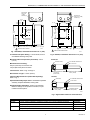
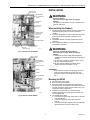
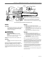
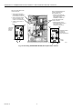
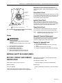
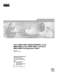
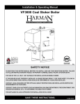
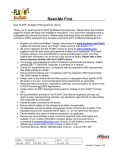
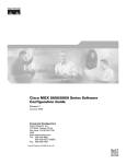
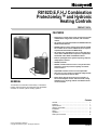
R8182D,E,F,H,J Combination
Protectorelay™ and Hydronic
Heating Controls
PRODUCT DATA
FEATURES
• Depending on model, these single unit devices provide
combinations of high limit, low limit, and circulator
control.
• All models use a 24V thermostat and C554A Cadmium
Sulfide Flame Detector.
• R8182D,E,H and J have auxiliary terminals ZC and ZR
for circulator zone control. Additional zones require a
separate 24V thermostat and R845 Relay.
• All models have capability for zone control with zone
valves. Each additional zone requires a separate 24V
thermostat and a V8043 or V8044 Zone Valve.
• Ideal for packaged boiler systems requiring compact,
multipurpose controls.
• R8182D,E,F mode
• R8182H,J models mount on a 4 x 4 inch junction box,
and have a 5 ft (1.5m) armored capillary for remote
sensor location.
• Aquastat® Controller section is field replaceable.
• Oil burner circuit includes an improved safety shutoff
in the event the burner fails to start.
GENERAL
• Flame failure during the running cycle results in a
45 second attempt to restart. If unsuccessful, safety
shutoff occurs, requiring manual reset before burner
can be restarted.
The R8182 is a combination Protectorelay™ intermittent
ignition oil burner primary and immersion type Aquastat®
controller for oil-fired, hydronic heating systems.
Contents
General ............................................................................. 1
Features ........................................................................... 1
Specifications ................................................................... 2
Ordering Information ........................................................ 2
Installation ........................................................................ 5
Wiring ............................................................................... 7
Operation .......................................................................... 12
Startup and Checkout ....................................................... 14
® U.S. Registered Trademark
Copyright © 2002 Honeywell • All Rights Reserved
68-0105-2
R8182D,E,F,H,J COMBINATION PROTECTORELAY™ AND HYDRONIC HEATING CONTROLS
SPECIFICATIONS
IMPORTANT
The specifications given in this publication do not
include normal manufacturing tolerances. Therefore,
this unit may not exactly match the listed
specifications. Also, this product is tested and
calibrated under closely controlled conditions, and
some minor differences in performance can be
expected if those conditions are changed.
TRADELINE® Models: TRADELINE® models are selected
and packaged for ease of handling, ease of stocking, and
maximum replacement value. TRADELINE® model
specifications are the same as those of standard models
except as noted below.
TRADELINE® Models Available:
R8182D Combination Protectorelay™ Primary Control and
Aquastat® Controller.
R8182H Combination Protectorelay™ Primary Control and
Aquastat® Controller.
Additional Features:
• Well not included. To order wells or well adapters, refer to
form 68-0040, Wells and Fittings for Temperature
Controllers, for part numbers and descriptions.
• Heat-conductive compound supplied for better bulb
response in oversized well.
• Field addable stops for Aquastat® Controller.
• Conversion to R8182E or F.
• TRADELINE® pack with special instructions.
• Wire nut.
Mounting Means:
R8182D,E,F: Case clamps to horizontal immersion well
installed through boiler wall.
R8182H,J: Mounts on standard 4 x 4 inch junction box.
Dimensions: Refer to Fig. 1 and 2.
Table 1. Standard Models:
Adjustable Control Range
Model
R8182Da
R8182Ea
R8182F
R8182Ha Remote Bulb
a
R8182J Remote Bulb
a
Switching
°F
Differential
°C
°F
°C
High Limit, Spst
130 to 240
54 to 116
10 Fixed
6 Fixed
High Limit/Circulator, Spdt
110 to 220
43 to 104
10 to 25 Adj
6 to 14 Adj
High Limit, Spst
180 to 240
82 to 116
15 Fixed
8 Fixed
High Limit, Spst
130 to 240
54 to 116
10 Fixed
6 Fixed
Circulator, Spst
110 to 220
43 to 104
10 Fixed
6 Fixed
High Limit, Spst
130 to 240
54 to 116
10 Fixed
6 Fixed
Low Limit/Circulator, Spdt
110 to 220
43 to 104
10 to 25 Adj
6 to 14 Adj
High Limit, Spst
180 to 240
82 to 116
15 Fixed
8 Fixed
Auxiliary ZC and ZR terminals can be used to provide circulator zone control through an R845A Switching Relay.
Electrical Ratings:
Power Supply: 120 Vac, 60 Hz.
Ignition: 360 VA in addition to motor load rating.
Maximum Power Consumption:
R8182D,E,H and J: 9W.
R89182F: 5.5W.
Burner Circulator Contact Rating: 4.4A full load; 26.4A locked
rotor at 120 Vac.
Safety Switch Timing: Approximately 45 seconds.
Flame Detector Required: C554A Cadmium Sulfide Flame
Detector (ordered separately).
Thermostat Required: 24V, 2-wire thermostat such as the
T87F.
ORDERING INFORMATION
When purchasing replacement and modernization products from your TRADELINE® wholesaler or distributor, refer to the
TRADELINE® Catalog or price sheets for complete ordering number.
If you have additional questions, need further information, or would like to comment on our products or services, please write or
phone:
1. Your local Home and Building Control Sales Office (check white pages of your phone directory).
2. Home and Building Control Customer Relations
Honeywell, 1885 Douglas Drive North
Minneapolis, Minnesota 55422-4386
In Canada—Honeywell Limited/Honeywell Limitée, 35 Dynamic Drive, Scarborough, Ontario M1V 4Z9.
International Sales and Service Offices in all principal cities of the world. Manufacturing in Australia, Canada, Finland, France,
Germany, Japan, Mexico, Netherlands, Spain, Taiwan, United Kingdom, U.S.A.
68-0105—2
2
R8182D,E,F,H,J COMBINATION PROTECTORELAY™ AND HYDRONIC HEATING CONTROLS
KNOCKOUTS
FOR 1/2 IN.
(13 MM)
CONDUIT (5)
KNOCKOUTS
FOR 1/2 IN. (13 MM)
CONDUIT (5)
2-7/16
(62)
1-5/16
(33)
3-3/8 (86)
1/2 (13)
1
1
7/8
(22)
VERTICAL
MOUNT
ONLY
7-1/8
(181)
3-7/16
(87)
7-1/8
(181)
3-9/16
(91)
3/16
(5)
HORIZONTIAL
MOUNT ONLY
5-1/4 (133)
1
3-1/4 (83)
VERTICAL MOUNT SHOWN.
3-7/16 (87)
5-1/4 (133)
M4517
1
SIDE MOUNTED HINGE SHOWN.
Fig. 1. R8182D,E,F installation dimensions in in. (mm).
M4518
Fig. 2. R8182H,J installation dimensions in in. (mm).
Thermostat Anticipator Setting: 0.2A for R8182, 0.4A for
each R845A Switching Relay used.
Maximum Ambient Temperature (at Element): 250°F
(121°C).
R8182D,E,F
FITS BOILER TAPPED HOLE
CONTROL MOUNT
1/2 OR 3/4 NPT
Maximum Pressure Rating:
200 psi (1379 kPa) on immersion well.
100 psi (689.5 kPa) direct immersion.
Internal Views: Refer to Fig. 4 through 8.
INSULATION LENGTH
1-1/2 OR 3 IN.
(38 OR 76 MM)
Well Insertion Length: 3-3/8 in. (86 mm).
Immersion Well Dimensions (Order Well Separately):
Refer to Fig. 3.
INSERTION LENGTH
3-3/8 IN. (86 MM)
R8182H,J
SETSCREW
Aquastat® Assembly Repair Parts: 125026AAE Aquastat®
Assembly: Replaces R8182D,F Sensing Bulb.
Replacement Well Assemblies: Refer to form 68-0040,
Wells and Fittings for Temperature Controllers, for part
numbers and descriptions.
FITS BOILER TAPPED HOLE
1/2 OR 3/4 NPT
INSULATION LENGTH
1-1/2 IN. (38 MM)
INSERTION LENGTH
3-3/8 IN. (86 MM)
M4530
Fig. 3. Approximate immersion well dimensions.
Device
R8182D
R8182E
Description
1-1/2 in. (38 mm) insulation, horizontal or vertical; 3 in. (76 mm) insulation horizontal.
Part Number
125026AAD
3 in. (76 mm) insulation, vertical.
1250266AAE
1-1/2 in. (38 mm) insulation, horizontal or vertical; 3 in. (76 mm) insulation horizontal.
123726AV
3 in. (76 mm) insulation, vertical.
123726AW
3
68-0105—2
R8182D,E,F,H,J COMBINATION PROTECTORELAY™ AND HYDRONIC HEATING CONTROLS
Device
R8182F
R8182H
Description
Part Number
1-1/2 in. (38 mm) insulation, horizontal or vertical; 3 in. (76 mm) insulation horizontal.
125017AAB
3 in. (76 mm) insulation, vertical.
125017AAC
1-1/2 in. (38 mm) insulation.
125026AAJ
R8182J
123726AT
Dial Stop: For restricting range, part no. 4074BRR for
R8182D,F,H.
GROUNDING SCREW
Optional Specifications:
R8182D,E,F: Case with long dimension horizontal.
R8182H,J: End mounted hinge.
GROUNDING SCREW
SAFETY SWITCH
RESET BUTTON
TRANSFORMER
FOR THERMOSTAT
CIRCUIT
AQUASTAT SWITCH
SAFETY SWITCH
RESET BUTTON
TRANSFORMER
FOR THERMOSTAT
CIRCUIT
CIRCULATOR
RELAY (1K)
DIFFERENTIAL
SETTING
BURNER MOTOR
AND IGNITION
RELAY (2K)
CIRCULATOR
RELAY (1K)
BURNER MOTOR
AND IGNITION
RELAY (2K)
VOLTAGE BARRIER
LOW LIMIT
SETTING
HIGH LIMIT
SETTING
VOLTAGE BARRIER
TRANSFORMER FOR
CAD CELL CIRCUIT
M4532
Fig. 5. Internal view of R8182E.
HIGH LIMIT
SETTING
TRANSFORMER FOR
CAD CELL CIRCUIT
GROUNDING SCREW
M4525
SAFETY SWITCH
RESET BUTTON
Fig. 4. Internal view of R8182D.
HIGH LIMIT
SETTING
BURNER MOTOR
AND IGNITION
RELAY (2K)
LOW LIMIT
SETTING
TRANSFORMER FOR
CAD CELL CIRCUIT
VOLTAGE BARRIER
M4515
Fig. 6. Internal view of R8182F.
68-0105—2
4
R8182D,E,F,H,J COMBINATION PROTECTORELAY™ AND HYDRONIC HEATING CONTROLS
INSTALLATION
SAFETY SWITCH
RESET BUTTON
WARNING
TRANSFORMER
FOR THERMOSTAT
CIRCUIT
Explosion Hazard.
Can cause severe injury, death or property
damage.
This product is intended for use only in systems with a
pressure relief valve.
DIFFERENTIAL
SETTING
CIRCULATOR
RELAY (1K)
When Installing this Product…
1.
BURNER MOTOR
AND IGNITION
RELAY (2K)
2.
LOW LIMIT
SETTING
3.
VOLTAGE BARRIER
4.
HIGH LIMIT
SETTING
TRANSFORMER FOR
CAD CELL CIRCUIT
CAD CELL
M4524
LEADS (YELLOW)
Read these instructions carefully. Failure to follow them
could damage the product or cause a hazardous
condition.
Check the ratings given in these instructions and on the
product to be sure the product is suitable for your
application.
The installer must be a trained, experienced service
technician.
After completing installation, use these instructions to
check product operation.
WARNING
Explosion or Electrical Shock Hazard.
Can cause severe injury, death or property
damage.
1. Disconnect the power supply before beginning
installation to prevent electrical shock or equipment
damage.
2. Be sure that combustion chamber is clear of oil or
oil vapor before starting burner.
3. Be sure that the ambient temperature at the
element will not exceed 250°F (121°C).
Fig. 7. Internal view of R8182H.
SAFETY SWITCH
RESET BUTTON
TRANSFORMER
FOR THERMOSTAT
CIRCUIT
AQUASTAT SWITCH
IMPORTANT
Be sure that the sensing bulb fits snugly inside the
immersion well and that the sensing bulb rests
against the bottom of the immersion well. Refer to
Fig. 9.
2K RELAY
1K RELAY
VOLTAGE BARRIER
Mounting the R8182
TRANSFORMER
FOR CAD CELL
CIRCUIT
1.
2.
3.
HIGH LIMIT
SETTING
CAD CELL LEADS (YELLOW)
4.
M4531
5.
Fig. 8. Internal view of R8182J.
5
Disconnect the power supply.
Drain all water from the boiler.
Generally, boilers are equipped with a tapping that
allows horizontal mounting of the immersion well where
average temperature boiler water circulates freely. If no
tapping is provided, prepare one.
Install the immersion well or compression fitting
(ordered separately) by threading the immersion well
into the tapped hole.
For R8182D,E,F models:
a. Loosen the immersion well clamp screw on the side
of the R8182 case.
b. Insert the bulb into the immersion well until it
bottoms.
c. If necessary, bend the capillary tube to hold the bulb
against the bottom of the immersion well.
68-0105—2
R8182D,E,F,H,J COMBINATION PROTECTORELAY™ AND HYDRONIC HEATING CONTROLS
NOTE: Do not make sharp bends in the tubing. A sharp
bend can break the tubing and cause a loss of fill. In
models with an adjustable tubing length, pull the
extra tubing out of the controller case.
6.
d. Fit the controller case onto the immersion well so
that the immersion well clamp slides over the flange
of the immersion well.
e. Securely tighten the immersion well clamp screw.
For R8182H,J models:
a. Loosen the screw holding the hinged backplate to
the controller case and swing the backplate away
from the controller case.
b. Screw the backplate to a 4 by 4 inch junction box.
c. Insert the bulb into the immersion well until it
bottoms.
d. If necessary, bend the capillary tube to hold the bulb
against the bottom of the immersion well.
NOTE: Do not make sharp bends in the tubing. A sharp
bend can break the tubing and cause a loss of fill. In
models with an adjustable tubing length, pull the
extra tubing out of the controller case.
7.
e. Tighten the immersion well screw over the brass
collar.
f. After wiring, swing control against the backplate and
refasten with the screw.
Refill the boiler and check for water leakage.
Mounting the R8182D TRADELINE®
If the existing immersion well does not fit the R8182D
immersion well clamp, use a 1249094 immersion well adapter
(order separately; see form 68-0040, Wells and Fittings for
Temperature Controllers).
1.
2.
3.
4.
5.
6.
Disconnect the power supply.
Drain all water from the boiler.
Fasten the R8182D immersion well clamp to the flange
on the immersion well adapter. Refer to Fig. 9.
Place the adapter on the capillary tube.
Put the adapter end into the hole in the controller case
and tighten the clamp screw.
Insert the sensing bulb into the immersion well and
bend the capillary tubing, if necessary, to hold the
sensing bulb against the bottom of the immersion well.
68-0105—2
6
NOTE: Do not make sharp turns while bending the capillary
tubing. In models with an adjustable tubing length,
pull the extra tubing out of the controller case.
7.
Apply the heat-conductive compound into the
immersion well (if necessary).
a. Fold the plastic bag of heat-conductive compound
lengthwise and twist it gently.
b. Cut off the end of the plastic bag and work the open
end of the bag all the way into the immersion well.
c. Slowly pull the bag out of the immersion well while
squeezing it firmly to evenly distribute the
heat-conductive compound.
8. Wipe off any excess grease and tighten the set screw
against the adapter.
If the existing immersion well is not usable, remove the
existing immersion well and order a new one using form
68-0040, Wells and Fittings for Temperature Controllers.
1.
2.
3.
4.
5.
Disconnect the power supply.
Drain all water from the boiler.
Install the new immersion well by threading it into the
threaded hole.
Loosen the immersion well clamp screw. See Fig. 9.
Insert the sensing bulb into the immersion well and
bend the capillary tubing, if necessary, to hold the
sensing bulb against the bottom of the immersion well.
NOTE: Do not make sharp turns while bending the capillary
tubing. In models with an adjustable tubing length,
pull the extra tubing out of the controller case.
6.
7.
8.
9.
Apply heat-conductive compound into the immersion
well (if necessary).
a. Fold the plastic bag of heat-conductive compound
lengthwise and twist it gently.
b. Cut off the end of the plastic bag and work the open
end of the bag all the way into the immersion well.
c. Slowly pull the bag out of the immersion well while
squeezing it firmly to evenly distribute the
heat-conductive compound.
Be sure the immersion well fits the hole in the controller
case.
Position the immersion well clamp snugly over the
immersion well flange. Securely tighten the clamp
screw.
Refill the boiler and check for water leakage.
R8182D,E,F,H,J COMBINATION PROTECTORELAY™ AND HYDRONIC HEATING CONTROLS
CONTROLLER
CASE
IMMERSION
WELL CLAMP
BACK OF
CONTROLLER
CASE
BOILER
IMMERSION
WELL CLAMP
1
IMMERSION
WELL SPUD
ADAPTER
ADAPTER
OLD IMMERSION
WELL ASSEMBLY
IMMERSION
WELL CLAMP
SCREW
SENSING
BULB
(A)
(D)
(C)
(B)
2
HEAT-CONDUCTIVE COMPOUND
1
CAPILLARY
TUBE
2
ASSURE THAT CAPILLARY TUBE FITS FREELY IN THE ADAPTER SO THE
TENSION OF THE CAPILLARY TUBE AT POINT (C) HOLDS THE SENSING
BULB IN GOOD THERMAL CONTACT WITH THE IMMERSION WELL AT POINT (D).
SETSCREW
IMMERSION
WELL CLAMP SCREW
BEND THE CAPILLARY TUBE TO HOLD THE SENSING BULB IN GOOD
THERMAL CONTACT WITH THE IMMERSION WELL AT POINTS (A) AND (B).
SHORT TUBE
FITS IN CENTRAL
RECESS OF ADAPTER
M8830
Fig. 9. Positioning the sensing bulb in the immersion well.
WIRING
Method 1
IMPORTANT
Use Underwriters Laboratories Inc. listed connectors
when making external circuit connections to the
orange and white line voltage burner and ignition
leadwires of the R8182H,J.
WARNING
1.
2.
3.
4.
Strip 7/16 in. of insulation from the wire end.
Wrap the wire 3/4 of the distance around the screw as
shown in method 1.
Using a standard, flat-headed screwdriver, tighten the
screw until the wipe is snugly in contact with the screw
and contact plate.
Tighten the screw pin an additional one-half turn.
Method 2
Electrical Shock Hazard.
Can cause severe injury, death or property
damage.
Disconnect power supply before wiring to prevent
electrical shock or equipment damage.
1.
2.
3.
4.
All wiring must comply with local codes, regulations, and
ordinances.
Strip 5/16 in. of insulation from the wire end.
Insert wire beneath the screw as shown in method 2.
Using a standard, flat-heat screwdriver, tighten the
screw until the wire is snugly in contact with the screw
and contact plate.
Tighten the screw an additional one-half turn.
NOTE: Do not use a push-type ratchet screwdriver.
IMPORTANT
Terminals on the R8182 are approved for copper
wire only.
The TRADELINE® R8182D,H can be converted to replace an
R8182B,C,E,F or a White Rodgers 6C92-2 or 6C92-3. When
replacing a White Rodgers model, the immersion well must
also be replaced. Refer to Fig. 10 for Aquastat® limit
connections necessary for each R8182D conversion.
Follow the wiring instructions furnished by the appliance
manufacturer, if available, or refer to Fig. 11 through 17. For
wiring multiple zoning systems, refer to Fig. 16 and 17.
To release the wires from the R8182, insert a screwdriver into
the rectangular hole adjacent to the wire, push inward to
release the locking-grip on the wire, and pull the wire out of
the terminal hole.
The R8182 is equipped with special wiring terminals. Wires
can be wrapped around the terminal screw or inserted from
the side.
To reinsert the wire into a new terminal hole, simply push the
wire into the new slot.
7
68-0105—2
R8182D,E,F,H,J COMBINATION PROTECTORELAY™ AND HYDRONIC HEATING CONTROLS
USING THE TRADELINE® R8182D
TO REPLACE R8182F:
USING THE TRADELINE® R8182D
TO REPLACE R8182B,E OR
WHITE RODGERS 6C92:
1. REMOVE BLUE WIRE FROM
THIS TERMINAL AND INSULATE
END TO PREVENT CONTACT.
1. REMOVE WHITE ABD BLACK
LEADS FROM THEIR TERMINAL
AND CONNECT WITH A
SODDERLESS CONNECTOR.
2. REMOVE OTHER BLUE WIRE
FROM THIS TERMINAL AND
CONNECT AS SHOWN BELOW.
TO USE TRADELINE® R8182H
TO REPLACE R8182J:
3. CONNECT CIRCULATOR TO
ZC AND C2.
BLUE
1. REMOVE RED AND WHITE
LEADS FROM THEIR TERMINALS
AND CONNECT WITH A
SOLDERLESS CONNECTOR.
WHITE
BLUE
COMPLETED
WIRING TO
REPLACE
R8182C,F
H
I
BLUE
COMPLETED WIRING
TO REPLACE
R8182B,E AND
WHITE RODGERS 6C92
L
O
H
I
YELLOW
L
O
BLACK
BLACK
OR RED
YELLOW
Fig. 10. Converting TRADELINE® R8182D,H to replace other controls.
68-0105—2
8
M4526
R8182D,E,F,H,J COMBINATION PROTECTORELAY™ AND HYDRONIC HEATING CONTROLS
1
L1
(HOT)
1
L1
(HOT)
L2
L2
R8182D
R8182E
2
4
1
G
1
G
2
3
ZR
1K2
BLUE
2K1
3
BLACK
B
R
B1
B
LOW
LIMIT
R
B2
C2
WHITE
W
HIGH LIMIT
2K2
ZR
HIGH LIMIT
BLUE
4
2
1K2
R
TO OIL
BURNER
AND
IGNITION
TO WATER
CIRCULATOR
C1
ZC
1K1
1K1
CIRCULATOR
B1
B2
C2
TO WATER
CIRCULATOR
C1
ZC
TO OIL
BURNER
AND
IGNITION
B
S.SW
CONTACTS
2
2K1
SAFETY
SWITCH
HEATER
S.SW
CONTACTS
2K2
SAFETY
SWITCH
HEATER
TRIAC
1K
2K
C1
T
C1
24 VOLT
THERMOSTAT
T
R2
F
T
R2
F
F
R1
BILATERAL
SWITCH
T
R1
BILATERAL
SWITCH
TRIAC
1K
2K
24 VOLT
THERMOSTAT
F
C554A
1
120 VAC POWER SUPPLY. PROVIDE DISCONNECT MEANS AND
OVERLOAD PROTECTION AS REQUIRED.
2
WHEN THE BLACK AND WHITE WIRES ON THE TRADELINE® R8182D
AQUASTAT® CONTROLLER ASSEMBLY ARE DISCONNECTED FROM
THE CIRCULATOR SWITCH AND ARE INTERCONNECTED, LOW LIMIT
AND CIRCULATOR CONTROL ARE BYPASSED. CIRCULATOR
OPERATES WITHY THEROMSTAT ONLY.
3
TO REPLACE R8182C,F, REMOVE BLUE WIRE AND INSULATE END.
DISCONNECT THE THE OTHER BLUE WIRE AT 4 AND WIRE TO B
AT 3. WHEN CIRCULATOR IS CONNECTED BETWEEN ZC AND C2,
LOW LIMIT FUNCTION IS REMOVED AND CIRCULATOR OPERATES
WITH CIRCULATOR CONTROL (R TO W) ONLY.
4
CONTROL CASE MUST BE CONNECTED TO EARTH GROUND.
USE GROUNDING SCREW PROVIDED.
M4519
C554A
1
120 VAC POWER SUPPLY. PROVIDE DISCONNECT MEANS AND
OVERLOAD PROTECTION AS REQUIRED.
2
CONTROL CASE MUST BE CONNECTED TO EARTH GROUND.
USE GROUNDING SCREW PROVIDED.
M4527
Fig. 12. R8182E internal schematic and wiring diagram.
Fig. 11. R8182D internal schematic and wiring diagram.
9
68-0105—2
R8182D,E,F,H,J COMBINATION PROTECTORELAY™ AND HYDRONIC HEATING CONTROLS
1
L1
(HOT)
1
L1
(HOT)
L2
L2
R8182H
R8182F
2
G
1
1
2
2
ZR
HIGH LIMIT
1K2
R
JUMPER
HIGH
LIMIT
R
W
C1
CIRCULATOR C2
CONTROL
B2
B
B1
2K2
B
TO WATER
CIRCULATOR
B
TO
BURNER
AND
IGNITION
R
2K1
ORANGE
R
WHITE
LOW
LIMIT
TO OIL
BURNER
AND
IGNITION
1K1
W
C1
ZC
CIRCULATOR
TO WATER
CIRCULATOR
C2
SAFETY
SWITCH
CONTACTS
S.SW
CONTACTS
2K1
T
2K
2K2
TRIAC
T
SAFETY
SWITCH
HEATER
BILATERAL
SWITCH
R1
TRIAC
1K
R2
F
2K
C1
R1
BILATERAL
SWITCH
F
T
YELLOW
T
C554A
1
120 VAC POWER SUPPLY. PROVIDE DISCONNECT MEANS AND
OVERLOAD PROTECTION AS REQUIRED.
2
CONTROL CASE MUST BE CONNECTED TO EARTH GROUND.
USE GROUNDING SCREW PROVIDED.
24 VOLT
THERMOSTAT
M4528
1
Fig. 13. R8182F internal schematic and wiring diagram.
C1
R2
YELLOW
24 VOLT
THERMOSTAT
SAFETY
SWITCH
HEATER
C554A
120 VAC POWER SUPPLY. PROVIDE DISCONNECT MEANS AND
OVERLOAD PROTECTION AS REQUIRED.
M4520
Fig. 14. R8182H internal schematic and wiring diagram.
68-0105—2
10
R8182D,E,F,H,J COMBINATION PROTECTORELAY™ AND HYDRONIC HEATING CONTROLS
1
L1
(HOT)
24 VOLT
THERMOSTAT
L2
24 VOLT
THERMOSTAT
24 VOLT
THERMOSTAT
R8182J
1
4
2
L1
(HOT)
L2
1
HIGH LIMIT
ZR
B
R
YELLOW
TO WATER
CIRCULATOR
1K1
C2
5
L1
RED
3
T
B1
T
B2
C1
2K
L2
TO OIL
BURNER
AND
IGNITION
RED
RED
SAFETY
SWITCH
HEATER
3
5
RED
RED
2K1
5
RED
3
S.SW
CONTACTS
C2
2
TRIAC
1K
R1
BILATERAL
SWITCH
C1
CIRCULATOR
1
POWER SUPPLY. PROVIDE DISCONNECT MEANS AND OVERLOAD
PROTECTION AS REQUIRED.
2
R8182H AND J HAVE WHITE AND ORANGE LEADWIRES FOR OIL
BURNER AND IGNITION CONNECTIONS.
3
RED LEADWIRES PROVIDED ONLY ON MODLES WITH END SWITCH.
4
CHOOSE AT72, AT87, OR AT88 TRANSFORMER TO MATCH
MAXIMUM SYSTEM LOAD.
5
USE V8043 OR V8044 ZONE VALVES WITH AUXILIARY END
SWITCH ONLY.
R2
F
F
YELLOW
YELLOW
T
24 VOLT
THERMOSTAT
1
YELLOW
C1
ZC
T
YELLOW
WHITE
YELLOW
2K2
YELLOW
1K2
YELLOW
TO OIL
BURNER
AND
IGNITION
ORANGE
C554A
120 VAC POWER SUPPLY. PROVIDE DISCONNECT MEANS
AND OVERLOAD PROTECTION AS REQUIRED.
M4522
Fig. 16. R8182D,E,F,H and J in a typical zoning
application using zone valves.
M4529
Fig. 15. R8182J internal schematic and wiring diagram.
11
68-0105—2
R8182D,E,F,H,J COMBINATION PROTECTORELAY™ AND HYDRONIC HEATING CONTROLS
6
ZONE 2
THERMOSTAT
L1
(HOT)
L2
1
2
1
R845A
SWITCHING
RELAY ZONE 2
R8182D
G
1K
3
5
T
BLUE
ZR
3
HIGH LIMIT
1K2
4
2K1
B
1K1
T
LOW
LIMIT
B2
C2
W
6
C1
ZC
TO OIL
BURNER
AND
IGNITION
TO WATER
CIRCULATOR
1K1
CIRCULATOR
2
B1
B
1K2
R
1
R
5
4
S.SW
CONTACTS
ZONE 2
CIRCULATOR
2K2
SAFETY
SWITCH
HEATER
TO ADDITIONAL
ZONES 3, 4, ETC.
1 120 VAC POWER SUPPLY. PROVIDE DISCONNECT
MEANS AND OVERLOAD PROTECTION AS REQUIRED.
TRIAC
1K
2 THERMOSTAT HEAT ANTICIPATOR SETTING, 0.2 AMP FOR R8182D.
R1
BILATERAL
SWITCH
3 THERMOSTAT HEAT ANTICIPATOR SETTING, 0.4 AMP FOR R845A.
4 CONTROL CASE MUST BE CONNECTED TO EARTH
GROUND. USE GROUNDING SCREW PROVIDED.
C1
T
5 R8182E,H,J CONNECTIONS FROM ZC AND ZR ARE IDENTICAL
FOR MULTIPLE CIRULATOR ZONING APPLICAITON.
6 EACH ADDITIONAL ZONE REQUIRES A SEPARATE,
FIELD-ADDED 24V THERMOSTAT AND R845 RELAY.
2K
T
R2
F
F
2
24 VOLT
THERMOSTAT
C554A
M4521
Fig. 17. R8182D and R845A in a typical multiple circulator zoning application.
OPERATION
R8182F
R8182D
A call for heat by the thermostat pulls in relay 1K, which
energizes the safety switch circuit and relay 2K to turn on the
burner. Safety switch starts to heat. If burner ignites within
safety switch timing, the cadmium sulfide flame detector sees
flame and the safety switch heater circuit is bypassed. The
burner operates until the call for heat is satisfied. The
circulator operates when relay 1K pulls in only if R to W is
made in the Aquastat¨ limit.
When R to B (low limit) is made by a drop in water
temperature, it acts as a call for heat, pulling in relay 2K to
turn on the burner. The circulator cannot operate. See Fig. 11,
16, 17 and 19.
R8182E
The burner and circulator operate whenever the thermostat
calls for heat. Relay 2K pulls in. When the cadmium sulfide
flame detector sees flame, the safety switch heater circuit is
bypassed, and 2K is held in through 2K1. If temperature rises
to a high limit setpoint, R to B breaks, shutting off the burner.
The circulator continues operation under the thermostat
direction. See Fig. 12, 16, 17 and 20.
68-0105—2
12
The thermostat call for heat pulls in relay 2K to turn on the
burner. When the cadmium sulfide the flame detector sees
flame, safety switch the heater circuit is bypassed. The
circulator is independent of the thermostat circuit, being
controlled only by the Aquastat¨ limit switch. See Fig. 13, 17
and 20.
R8182H
A call for heat by the thermostat pulls in relay 1K, which
energizes the safety switch circuit and relay 2K to turn on the
burner. The safety switch starts to heat. If the burner ignites
within the safety switch timing, the cadmium sulfide flame
detector sees the flame and the safety switch heater circuit is
bypassed. The burner shuts Off when a call for heat is
satisfied. The circulator operates when relay 1K pulls in only if
R to W in the Aquastat¨ limit is made.
When R to B (low limit) is made by a drop in water
temperature, it acts as a call for heat, pulling in relay 2K to
turn on the burner. The circulator cannot operate. See Fig. 14,
16, 17 and 18.
R8182D,E,F,H,J COMBINATION PROTECTORELAY™ AND HYDRONIC HEATING CONTROLS
R8182J
The burner and circulator operate whenever the thermostat
calls for heat. Relay 2K pulls in. When the cadmium sulfide
flame detector sees flame, the safety switch heater circuit is
bypassed, and 2K is held in through 2K1. If temperature rises
to a high limit setpoint, R to B breaks, shutting off the burner.
The circulator continues operation under direction of the
thermostat. See Fig. 15, 16, 17 and 19.
SWITCH BREAKS ON
TEMPERATURE RISE.
BURNER TURNS OFF.
CIRCULATOR OPERATES
ON A CALL FOR HEAT.
HIGH LIMIT
SETTING
SWITCH MAKES ON
TEMPERATURE FALL.
BURNER OPERATES ON A
CALL FOR HEAT.
Multizone Control
In all multizone applications, a call for heat in any zone
energizes the safety switch circuit and relay 2K pulls in. If the
burner ignites within the safety switch timing, the cadmium
sulfide flame detector sees flame and the safety switch heater
is bypassed.
SWITCH MAKES R-W
AND BREAKS R-B ON
TEMPERATURE RISE.
LOW LIMIT
AND
CIRCULATOR
SETTING
SWITCH MAKES R-W
AND BREAKS R-B ON
TEMPERATURE RISE.
In all multizone applications with R8182D and H, the low limit
control in the Aquastat® limit acts independently to turn on the
main burner on a drop in water temperature. When R to B (low
limit) is made, relay 2K pulls in to turn on the main burner, the
same as for single-zone application.
SWITCH MAKES R-B AND
BREAKS R-W ON
TEMPERATURE FALL.
BURNER IS ON TO
MAINTAIN MINIMUM
WATER TEMPERATURE.
CIRCULATOR IS OFF.
1
Zone Circulator Control with R8182D,H
The relay for each zone is connected to the Aquastat® limit
through terminals ZC and ZR. The R845 Relay and
thermostat for each zone can energize the zone circulator
through ZC only if R to W in the Aquastat® limit is made. If
R to B (high limit) is made, the zone thermostat energizes the
burner through ZR.
Zone Circulator Control with R8182E,J
The relay for each zone is connected to the Aquastat® limit
through terminals ZC and ZR. The R845A Relay and
thermostat in each zone can energize the zone circulator
through ZC on a call for heat. If R to B (high limit) is made, the
zone thermostat energizes the burner through ZR.
WHEN WATER REACHES PROPER TEMPERATURE, THE BURNER
SHUTS OFF OR THE CIRCULATOR PUMP STARTS (WHEN CALLING
FOR HEAT).
M1523
Fig. 18. R8182D,H Aquastat® limit switching.
240°F (116°C)
R-B BREAKS ON
TEMPERATURE RISE.
BURNER TURNS OFF.
CIRCULATOR OPERATES
ON A CALL FOR HEAT.
HIGH LIMIT
SETTING
15°F (8°C)
DIFFERENTIAL
R-B MAKES ON
TEMPERATURE FALL.
BURNER AND
CIRCULATOR OPERATE
ON A CALL FOR HEAT.
Zone Valve Control with R8182
The valve for each zone is connected to the Aquastat® limit
by wiring end switches on the zone valve to T-T on the R8182.
On a call for heat from any zone, the R8182 operates the
same as for single zone applications.
1
M1510
180°F (82°C)
Fig. 19. R8182E,J Aquastat® limit switching.
13
68-0105—2
R8182D,E,F,H,J COMBINATION PROTECTORELAY™ AND HYDRONIC HEATING CONTROLS
Low Limit/Circulator Setting—D And H
Models
240°F (116°C)
HIGH LIMIT
SETTING
10°F (6°C)
DIFFERENTIAL
CIRCULATOR
SETTING
10°F (6°C)
DIFFERENTIAL
On a temperature rise, with the adjustable differential at the
minimum setting of 10°F (6°C), the burner circuit (R-B) breaks
and the circulator circuit (R-W) makes at the low limit setpoint.
See Fig. 19. On a temperature drop of 10°F (6°C) below the
setpoint, the R-B circuit makes and the R-W circuit breaks.
R-B BREAKS ON
TEMPERATURE RISE.
BURNER TURNS OFF.
R-B MAKES ON
TEMPERATURE FALL.
BURNER OPERATES
ON CALL FOR HEAT.
At any differential setting greater than 10°F (6°C), the R-B
make temperature and R-W break temperature remains the
same— setting minus 10°F (6°C). The R-B break and R-W
make temperature are the setpoint temperature plus the
difference between the differential setting and 10°F (6°C).
R-W MAKES ON
TEMPERATURE RISE.
CIRCULATOR TURNS ON.
EXAMPLE: Setpoint of 140°F (60°C); differential set at 25°F
(14°C). On a temperature rise, R-B breaks and R-W makes at
155°F (68°C). On a temperature fall, R-B makes and R-W
breaks at 130°F (54°C).
R-B BREAKS ON
TEMPERATURE FALL.
CIRCULATOR TURNS OFF.
110°F (43°C)
Set the low limit indicator at the minimum temperature
recommended for domestic hot water supply. This setting
must be at least 20°F (11°C) below the high limit setting to
prevent one switch from locking out the other.
M1509
Fig. 20. R8182F Aquastat® limit switching.
Set the differential the desired number of degrees.
STARTUP AND CHECKOUT
Circulator Setting—F Models
Set the circulator indicator at the minimum water temperature
recommended for hydronic heating comfort.
WARNING
Explosion Hazard.
Can cause severe injury, death or property
damage.
This product is intended for use only in systems with a
pressure relief valve.
Because heating systems differ, the correct temperature
setting for one system may not be correct for another. Follow
the boiler manufacturers recommendations for proper
selection of settings.
Part no. 126580 Setting Stops can be installed on the low and
high limit adjusting knobs to prevent turning the knobs beyond
a predetermined point. To install the setting stops, proceed as
follows:
IMPORTANT
Once the setting stops are in place, they cannot be
replaced. If they must be removed, cut off with
cutters—do not twist off.
1.
High Limit Setting—All Models
The high limit opens and turns off the burner when the water
temperature reaches the setpoint. The high limit automatically
resets after the water temperature drops past the setpoint and
through the 10°F (6°C) [15°F (8°C) with R8182E,J] differential.
Set the indicator at the desired shutoff temperature.
68-0105—2
Setting Stops (R8182D,H TRADELINE®)
14
On low limit knob, turn the knob to the setting that is to
be established as the limit.
2. Place the setting stop over the knob so that the arm of
the setting stop (after the stop is pressed into place)
strikes projection A and prevents turning the knob
beyond the chosen limit setting. See Fig. 21.
3. Press the setting stop tightly onto the knob so its inner
teeth securely engage the knob.
4. Turn knob back and forth several times to make sure
stop functions properly.
5. Repeat steps 1 to 4 for the high limit knob.
After settings are made, replace the cover.
R8182D,E,F,H,J COMBINATION PROTECTORELAY™ AND HYDRONIC HEATING CONTROLS
Make certain the system operates as described in the
OPERATION section. Use the following procedure to verify
that the Protectorelay™ burner sequencing relay is controlling
properly.
1
STOP ARM
SETTING
Flame Failure Check
Shut off the oil supply hand valve while the burner is on. After
45 seconds, the safety switch locks out, the motor stops, and
the oil valve closes. Allow five minutes for the burner to cool,
then manually reset the safety switch.
140
120
16
0
PROJECTION "A"
SETTING STOP
Ignition Failure Check
Test by closing the oil supply while the burner is off. Run
through the starting procedure but do not open the oil supply
line hand valve. The safety switch locks out as in flame failure.
Then turn the oil back on, and reset the safety switch.
200
180
KNOB SET AT 140°F (60°C)
1
SCALE MARKINGS IN FAHRENHEIT ONLY.
Power Failure Check
M4523
Fig. 21. Setting stop in position to restrict low limit setting
to 180°F (82°C) or lower.
Turn off the power supply while the burner is on. When the
burner goes out, restore power and the burner will restart.
NOTE: If operation is not as described, see cover insert for
additional information and check wiring.
Startup
Aquastat® Controller Replacement
The Aquastat® limit section of the Protectorelay™ control is
field replaceable. When ordering a replacement assembly,
specify the complete model number of the R8182.
WARNING
Explosion Hazard.
Can cause severe injury, death or property
damage.
Be sure combustion chamber is free of oil or vapor.
1.
2.
3.
4.
5.
Replace the Aquastat® Limit
1.
2.
Push red reset button and release.
Open hand valve on oil supply line.
Set thermostat to call for heat.
Close line switch; burner will start.
Under normal conditions, burner operates until
thermostat is satisfied or line switch is opened.
3.
4.
Disconnect power supply.
On all models—Note the position of the connecting
wires.
Remove fastening screws and wires.
Remove Aquastat® limit and install the new assembly.
MATERIAL SAFETY DATA SHEET (MSDS)
SECTION 1. PRODUCT AND COMPANY
IDENTIFICATION.
Product Name: Heat conductive compound.
Manufacturer: Honeywell Inc., 1985 Douglas Drive North,
Minneapolis, MN 55422.
Date Released: October 8, 1999.
Emergency Telephone Information: 1-888-809-3787.
MSDS ID: DS9021.
NFPA Ratings:
Synonyms: MS1699.
Product Use: Heat conductive material used to enhance
contact and heat transfer in temperature sensor applications.
15
Health 0; Flammability 1; Reactivity 0; Personal Protection
B.
68-0105—2
R8182D,E,F,H,J COMBINATION PROTECTORELAY™ AND HYDRONIC HEATING CONTROLS
Section 2. Composition, Information on
Ingredients (Table 3).
Table 2. Ingredients of Heat Conductive Compounda.
Ingredients
CAS Number
Percent
PEL
TLV
No. 2 Lithium Complex Grease (70%):
Mineral Oil
64742-65-0
35-50
5 mg/m3
5 mg/m3
Mineral Oil
64742-62-7
20-25
5 mg/m3
5 mg/m3
Lithium Hydrostearate/Sebacate Complex
68815-49-6
4-9
—
—
Zinc Alkyldithiophosphate
68649-42-3
0-2
—
—
Aluminum, as Al
7429-90-5
20-25
15 mg/m3
10 mg/m3
Aliphatic Petroleum Distillates
8052-41-3
10-15
2900 mg/m3 525 mg/m3
—
Aluminum Paste (30%):
a
Stearic Acid
57-11-4
1-2
Aromatic Petroleum Distillates
64742-95-6
1-2
—
3
5 mg/m
5 mg/m3
Additional Information: Part No. 120650 (0.5 oz. tube); Part No. 107408 (4 oz. can); Part number 197007 (5 gallon container).
May also contain minute amounts of lithium and molybdenum lubricant compounds.
Section 3. Hazard Identification
Skin Contact:
Remove excess with cloth or paper. Wash thoroughly with
mild soap and water. Obtain medical attention if irritation
develops and persists.
Acute Health Effects:
Skin—Excessive contact can cause skin irritation and
dermatitis.
Ingestion:
Eye—Direct contact with eye will cause irritation.
Contact physician or local poison control center immediately.
Inhalation—No adverse effects are expected.
Inhalation:
Ingestion—Ingestion of product may cause nausea, vomiting
and diarrhea.
Remove patient to fresh air and obtain medical attention if
symptoms develop.
Chronic Health Effects:
Section 5. Fire Fighting Measures
Existing skin rash or dermatitis may be aggravated by
repeated contact.
Flash Point:
>383°F (195°C). Will burn if exposed to flame.
OSHA Hazard Classifications:
Extinguishing Media:
None.
Carbon dioxide, dry chemical or foam.
Carcinogenicity:
Not considered to be a carcinogen by either OSHA, NTP,
IARC, or ACGIH.
Special Fire Fighting Procedures:
Target Organs:
Explosion Hazards:
None.
None known.
Section 4. First Aid Measures
None. Aluminum powder can react with water to release
flammable hydrogen gas. In the form of this product, this
reaction is not expected.
Eye Contact:
Section 6. Accidental Release Measures
Scrape up and dispose as solid waste in accordance with
state and federal regulations.
Flush eyes with water for 15 minutes. Remove any contact
lenses and continue to flush. Obtain medical attention if
irritation develops and persists.
Section 7. Handling and Storage
Store in dry place. Keep container closed when not in use.
68-0105—2
16
R8182D,E,F,H,J COMBINATION PROTECTORELAY™ AND HYDRONIC HEATING CONTROLS
Section 8. Exposure Controls and Personal
Protection
Incompatibilities:
Strong oxidizing agents and halogens.
Hazardous Decomposition Products:
Ventilation:
Carbon dioxide, carbon monoxide.
No special ventilation is required when working with this
product.
Section 11. Toxicology Information
Respiratory Protection:
No data available.
None required.
Section 12. Ecological Information
Eye Protection:
Not normally required. However, use chemical safety goggles
or faceshield if potential for eye contact exists, especially if
material is heated.
Hand/Clothing Protection:
Not normally required. Protective gloves and clothing are
recommended, as material is difficult to remove from skin and
clothing.
Other Protective Equipment:
Chemical Fate Information:
Hydrocarbon components will biodegrade in soil; relatively
persistent in water.
Section 13. Disposal Consideration
Dispose of as solid waste in accordance with Local, State and
Federal regulations.
Section 14. Transportation Information
None required.
Section 9. Physical and Chemical Properties
Appearance/Odor:
DOT Classification:
Not classified as hazardous.
Section 15. Regulatory Information
Aluminum color, semi-solid material, pleasant odor.
SARA Title III Supplier Notification:
Solubility in Water:
0.86.
Include in Section 311/312 inventory reports if amounts
exceed 10,000 pounds. Aluminum compounds are subject to
the reporting requirements under Section 313 of Emergency
Planning and Community Right-to-Know Act of 1986 (40 CFR
372). Ingredients listed in TSCA Inventory.
Section 10. Stability and Reactivity
Section 16. Other Information
Negligible.
Specific Gravity:
This information is furnished without warranty, expressed or
implied, except that it is accurate to the best of our knowledge.
Stability:
Stable.
Prepared By:
Reactivity:
PROSAR, 1295 Bandana Boulevard, Suite 335, St. Paul, MN
55108 (651-917-6100).
Hazardous polymerization will not occur.
17
68-0105—2
68-0105—2
18
19
68-0105—2
Automation and Control Solutions
Honeywell
Honeywell Limited-Honeywell Limitée
1985 Douglas Drive North
35 Dynamic Drive
Golden Valley, MN 55422
Scarborough, Ontario
M1V 4Z9
68-0105—2
G.R. Rev. 1-02
Printed in U.S.A. on recycled
paper containing at least 10%
post-consumer paper fibers.
www.honeywell.com/building/components