1
US 20130194030Al
(19) United States
(12) Patent Application Publication (10) Pub. No.: US 2013/0194030 A1
Steckman
(54)
(43) Pub. Date:
METHOD AND APPARATUS FOR
(52)
TAP-SENSING ELECTRONIC SWITCH T0
TRIGGER A FUNCTION IN AN ELECTRONIC
Aug. 1, 2013
US. Cl.
CPC .................................. .. H03K17/945 (2013.01)
UsPC ........................................................ .. 327/517
EQUIPMENT
(57)
(71) Applicant: Michael Steckman, Los Angeles, CA
(Us)
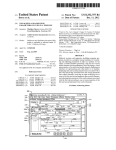
ABSTRACT
An electronic sWitch, or an electronic equipment having such
sWitch that has a tap-sensing detection region for a user to
(72) Inventor: Michael Steckman, Los Angeles, CA
(Us)
perform ?nger-tapping, foot-tapping, or other ?nger move
(21) Appl. No.: 13/757,711
plated functions of the electronic equipment. This sWitch
(22)
Filed:
Feb. 1, 2013
Related US. Application Data
(60)
Provisional application No. 61/593,686, ?led on Feb.
emits a radiation, such as infrared light, toWards the detection
region. The re?ection of the radiation off of an object is
collected and compared to a predetermined value. If there is a
match, the sWitch Would send a signal to the device to perform
the predetermined function. In operation, the sWitch Would
alloW an electrical equipment to have a “virtual sWitch” Where
the user can control the device by manipulating his ?nger or
1, 2012.
Publication Classi?cation
(51)
ments on a contact surface in this region and effectuate send
ing of a signal to turn on, turn off, or perform other contem
Int. Cl.
H03K 17/945
(2006.01)
his foot in the designated detection region. The equipment
may optionally have a LED illuminator to shine a lit marking
indicating Where the contact surface is and hoW it is to be
used.
014
1011
Patent Application Publication
Aug. 1, 2013 Sheet 1 0f 12
{14.
FIG. 1
US 2013/0194030 A1
‘gm
Patent Application Publication
Aug. 1, 2013 Sheet 2 0f 12
M
US 2013/0194030 A1
: 1m
3
m
r ‘I new;
i
Patent Application Publication
Aug. 1, 2013 Sheet 3 0f 12
US 2013/0194030 A1
Patent Application Publication
Aug. 1, 2013 Sheet 4 0f 12
US 2013/0194030 A1
Patent Application Publication
Aug. 1, 2013 Sheet 5 0f 12
US 2013/0194030 A1
'a aim
FIG. 5
.1. £335
v a mi:
Patent Application Publication
Aug. 1, 2013 Sheet 6 0f 12
US 2013/0194030 A1
m
Mm
Patent Application Publication
Aug. 1, 2013 Sheet 7 0f 12
FIGL “£0
US 2013/0194030 A1
Patent Application Publication
Aug. 1, 2013 Sheet 8 0f 12
US 2013/0194030 A1
1 213%
ERAEQURUQM
m
v
H6. 12
Patent Application Publication
Aug. 1, 2013 Sheet 9 0f 12
P16. 33
US 2013/0194030 A1
Patent Application Publication
Aug. 1, 2013 Sheet 10 0f 12
FIG. 14
US 2013/0194030 A1
Patent Application Publication
Aug. 1, 2013 Sheet 11 0f 12
US 2013/0194030 A1
m0c.o?nmwz @8325
D.
5o052
Q9 EUmtoLzuo_m\ ._
ma.OE
:6hHo?mu:co k
Ek
:H
62m6m:
Lysol
Patent Application Publication
Aug. 1, 2013 Sheet 12 0f 12
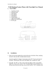
Flowchart
Main
initiaiize HW
No
Motion?
Yes
Generate
Command
FIG. 16
US 2013/0194030 A1
Aug. 1,2013
US 2013/0194030 A1
METHOD AND APPARATUS FOR
TAP-SENSING ELECTRONIC SWITCH TO
TRIGGER A FUNCTION IN AN ELECTRONIC
the above-mentioned desires, it should be understood that
some aspects of the invention might not necessarily obviate
them.
EQUIPMENT
BRIEF SUMMARY OF THE INVENTION
CROSS-REFERENCE TO RELATED
APPLICATIONS
[0011]
The inventive subject matter contemplated is an
electrical sWitch capable of sending a command to an elec
This application claims priority to US. Provisional
tronic equipment to turn on/off, increase/decrease volume,
Patent No. 61/593,686, ?led on Feb. 1, 2012, noW pending,
and/or other useful commands, based on a user’s ?nger
tapping motion Within a certain detection region. More
[0001]
Which is hereby incorporated by reference in its entirety.
broadly speaking, the contemplated sWitch can be designed to
BACKGROUND OF THE INVENTION
[0002] (1) Field of the Invention
[0003] The ?eld of the invention is electrical sWitches, and
electrical controllers.
[0004]
(2) Description of Related Art Including Informa
tion Disclosed Under 37 CFR 1.97 and 1.98
[0005] Typical electronics have poWer sWitches or control
sWitches placed on the body of electronic equipment for a
user to control operation of the electronic equipment. Having
such sWitches on the body of the electronic equipment can
negatively hinder/restrict the aesthetic creativity in the design
of the overall looks. This is because the designer Would noW
have to consider blending the controller design into the rest of
the overall design.
[0006] There have been attempts to minimize siZe of con
trollers so that controller features are less prominent to the
eyes. An example of this is televisions With small buttons.
Other attempts include positioning such buttons on the side of
the television so these controllers are not readily seen. There
are undesirable drawbacks to these solutions. Buttons that are
hidden made it harder for a user to control the device. Also,
buttons that are small made it harder for people With big hands
to accurately press the right buttons.
[0007] There have been discussions in the industry about
electronic equipments that recogniZe hand gestures of a user,
and certain hand gestures represent certain commands to the
electronic equipment. The disadvantage of this type of con
trol is that it may not be appropriate for people With certain
disabilities. Also, it may be harder for older people to learn
about this type of controller.
detect many types of user movement Within a certain detec
tion region. In more speci?c embodiments, it can detect a
foot-tapping, ?nger-tapping, a ?nger performing a “sliding”
action across a surface in a detection region, a ?nger perform
ing a “circling” action across a surface in a detection region,
etc. In general, as long as certain contemplated conditions
(that are detectable based on re?ective radiation) are met
Within a detection region, the sWitch Will send the contem
plated command to the electronic equipment. Various con
templated conditions Will be discussed in more details beloW.
[0012] This sWitch can be used to control various types of
electronic equipment. One skilled in the art Will recogniZe
that any knoWn electronic equipment requiring user control
can implement the instant inventive subject matter. While
some electronic equipment, depending on its usage and the
environment to Which it is used, may not be appropriate to use
the contemplated sWitch system, one skilled in the electronic
art can readily determine Whether or not the contemplated
sWitch disclosed herein can be appropriately implemented in
an electronic equipment of choice, to achieve the desired
objective of controlling by ?nger-tapping/foot-tapping or
other ?nger movements on a surface.
[0013] Among the various available electronic equipment
that are suitable for use With this sWitch, musical instruments
such as an electric drum set, or a virtual bass drum, Would
Work particularly Well.
[0014] Other contemplated consumer electronic products
are, lighting ?xtures, audio/visual equipment, and electroni
cally controlled Water faucets.
[0015] As for the technology behind detecting contem
plated motions Within the detection region, the contemplated
[0008] Another problem the industry has alWays tried to
electrical sWitch has a radiation source to project a projected
resolve is to create effective child-proof controllers for elec
tronic devices. Young children are quick to recogniZe Where
buttons are on electronic equipment, and parents often have to
place electronic equipment out of the reach of their children to
radiation into this detection region. The radiation is detect
prevent their children from playing With expensive equip
ment.
[0009]
There continues to be a need for effective Ways to
provide electronic control sWitches that is child-proof. And,
there continues to be a need for a Way to discreetly place
sWitches and control elements on electronic equipment. Fur
ther, there continues to be a need for easy-to-learn controller
sWitches.
[0010] All referenced patents, applications and literatures
are incorporated herein by reference in their entirety. Further
more, Where a de?nition or use of a term in a reference, Which
is incorporated by reference herein, is inconsistent or contrary
able based on the re?ection of the radiation off of Whatever
object located Within the detection region, as Will be dis
cussed in further detail beloW.
[0016] The contemplated system further includes a detector
and a microprocessor to collect and process raW data relating
to the re?ection from the detection region. The sWitch Will
recogniZe certain patterns, Within a reasonable degree of
error, that match the predetermined triggering patterns.
[0017]
The detector as mentioned above may be located at
various angles and locations of the electrical equipment to
Which the contemplated system controls. The detector can
also be located physically separate from the main housing of
the device. Preferably, the detector is located someWhere
above the detection region.
[0018] In essence, the contemplated system Would alloW an
to the de?nition of that term provided herein, the de?nition of
that term provided herein applies and the de?nition of that
term in the reference does not apply. The invention may seek
ible sWitch,” Where the user can control the device by tapping
his ?nger or tapping his foot in the designated detection Zone.
to satisfy one or more of the above-mentioned desires.
Although the present invention may obviate one or more of
be implicit.
electrical equipment to have a “virtual sWitch,” or an “invis
The designation of the detection Zone can be explicit, and can
Aug. 1,2013
US 2013/0194030 A1
[0019] Various objects, features, aspects and advantages of
the present invention Will become more apparent from the
following detailed description of preferred embodiments of
the invention, along With the accompanying draWings in
Which like numerals represent like components.
BRIEF DESCRIPTION OF THE DRAWINGS
[0020] It should be noted that the draWing ?gures may be in
simpli?ed form and might not be to precise scale. In reference
to the disclosure herein, for purposes of convenience and
clarity only, directional terms, such as, top, bottom, left, right,
up, doWn, over, above, beloW, beneath, rear, front, distal, and
proximal are used With respect to the accompanying draW
ings. Such directional terms should not be construed to limit
the scope of the invention in any manner.
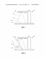
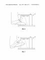
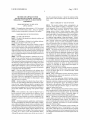
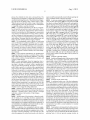
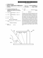
[0021] FIG. 1 is a side vieW of a ?rst embodiment of a
device having the contemplated detection unit and a desig
nated detection region according to an aspect of the inventive
subject matter.
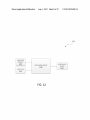
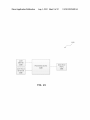
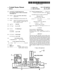
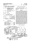
[0036] FIG. 13 is a more detailed block diagram of one
embodiment of a system such as that shoWn in FIG. 12.
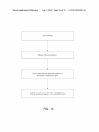
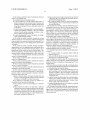
[0037] FIG. 14 is a How diagram of one embodiment ofa
method for controlling at least one feature of a controlled
device.
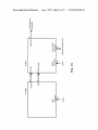
[0038] FIG. 15 is a setup diagram to process a trigger.
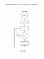
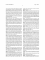
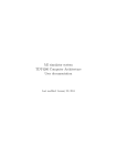
[0039] FIG. 16 is a How diagram of data processing/trigger
sensing algorithm.
DETAILED DESCRIPTION OF THE INVENTION
[0040]
The invention and its various embodiments can noW
be better understood by turning to the folloWing detailed
description of the preferred embodiments, Which are pre
sented as illustrated examples of the invention de?ned in the
claims. It is expressly understood that the invention as de?ned
by the claims may be broader than the illustrated embodi
ments described beloW.
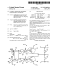
[0041]
Referring noW to FIG. 1, the contemplated device
100 has an electrical sWitch comprising a radiation source
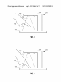
FIG. 2 is a side vieW of a ?rst embodiment of the
102 shining a radiation 103, a detector 104, a detection region
device in FIG. 1, With a user’s ?nger entering into the desig
nated detection Zone and placing the ?nger tip on a surface,
according to an aspect of the inventive subject matter.
105, a marked (i.e., explicitly indicated) or unmarked (i.e.,
implicitly indicated) contact surface 106 on an optional plat
[0022]
[0023]
FIG. 3 is a side vieW of a ?rst embodiment of the
device in FIG. 1, With a user’s ?nger raised from its position
in FIG. 2, according to an aspect of the inventive subject
matter.
[0024]
FIG. 4 is a side vieW of a ?rst embodiment of the
device in FIG. 1, With a user’ s ?nger loWered from its position
in FIG. 3, touching the surface, completing a tWo-tapping
motion, according to an aspect of the inventive subject matter.
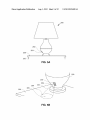
[0025]
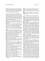
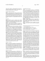
FIG. 5A is a side vieW of one embodiment of a desk
lamp implementing the inventive subject matter.
[0026]
FIG. 5B is a close-up perspective vieW of the desk
lamp of FIG. 5 illustrating its detection region.
[0027] FIG. 5C is a close-up perspective vieW of one
embodiment the desk lamp of FIG. 5 in operation Where its
detection Zone is implicit, and hidden.
[0028] FIG. 5D is a close-up perspective vieW of another
embodiment of the desk lamp of FIG. 5 in operation Where its
detection Zone is explicitly indicated on the table surface,
visible to a user.
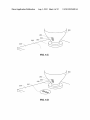
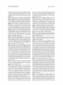
[0029] FIG. 6 is a side vieW of another embodiment of the
inventive subject matter to detect a foot-tapping motion
shoWing a user’s foot entering into the designated detection
Zone and placing the foot on a surface, according to an aspect
of the inventive subject matter.
[0030] FIG. 7 is a side vieW ofthe embodiment in FIG. 6,
With a user’s foot raised from its position in FIG. 6, according
to an aspect of the inventive subject matter.
[0031] FIG. 8 is a side vieW ofthe embodiment in FIG. 6,
With a user’s foot loWered from its position in FIG. 7, touch
ing the surface, completing a tWo-tapping motion, according
to an aspect of the inventive subject matter.
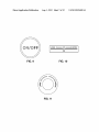
[0032] FIG. 9 is an illustration of one embodiment of
explicitly indicated sWitch for ?nger-tapping.
[0033]
FIG. 10 is an illustration of another embodiment of
explicitly indicated sWitch for ?nger-sliding.
[0034]
FIG. 11 is an illustration of one embodiment of
form 130, and a microprocessor 000. These elements Will
ensure that When the sWitch is used in combination With
electronic equipment, a user may effectuate certain predeter
mined functions of the electronic equipment by tapping a
?nger, tapping a foot, or by performing other motions in the
detection region, as Will be discussed in more details beloW.
[0042]
FIGS. 2-4 illustrate a series of ?nger-tapping motion
of hand 125 onto contact surface 106 of platform 130.
Although FIGS. 1-4 shoWs a tWo-tapping motion, it should be
understood that it is a choice of design to set the threshold
value at only one tapping, or tWo-tapping, three-tapping, or
any other repetition of tapping.
[0043]
In one embodiment, a one-tapping motion, or a
single-tapping motion, is completed once the ?nger leaves the
contact surface 106 of platform 130 as shoWn in FIG. 3. In
another embodiment, the one-tapping motion is completed
once the ?nger lands on contact surface 106 of platform 130
as shoWn in FIG. 2.
[0044] In one embodiment, a tWo-tapping motion, or a
double-tapping motion, is completed once the ?nger in FIG.
4 leaves the contact surface 106. In another embodiment, the
tWo-tapping motion is completed once the ?nger lands on
contact surface 106 as shoWn in FIG. 4.
[0045]
Furthermore, the system may be designed such that
a speci?c number of tapping means a speci?c command. For
example, tWo-tapping means turn on the system, and ?ve
tapping means turn off the system. This type of design Would
avoid sending mistaken command, and avoid false turn-on.
[0046] In a preferred embodiment, the inventive subject
matter is the sWitch itself. In a further preferred embodiment,
the inventive subject matter is the electronic equipment
implementing such sWitch. In yet another preferred embodi
ment, the inventive subject matter is about a method of using
tap-sensing and other ?nger motion-sensing sWitches to oper
ate electronic equipment. In some preferred embodiments,
the contemplated sWitch Would alloW an electronic equip
ment to have a “virtual sWitch,” or “invisible sWitch” Where
the user can control the device by manipulating his ?nger or
explicitly indicated sWitch for ?nger-circling.
his foot on a contact surface (i.e., a surface) in a detection
[0035]
embodiment of a system that sends a command signal to a
region, Which can be physically separate or separable from
the electronic equipment. For example, in the embodiment as
controlled device,
shoWn in FIGS. 1-4, a user Would have to touch the platform
FIG. 12 is a high-level block diagram of one
Aug. 1,2013
US 2013/0194030 A1
130 (Which is part of the electronic device 100) in order to turn
piece, a ?oor, or on the Wall. The contemplated surface can be
on the device 100. In the example as shown in FIGS. 5A-5F,
a user may control the electronic equipment (i.e., the desk
lamp 200) Without having to physically touch the electronic
made of any suitable materials capable of alloWing “contact”
by a ?nger or by a foot, performing the contemplated move
ments illustrated in this speci?cation. The contact surface
equipment.
does not have to be ?at.
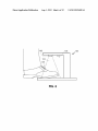
[0047] Referring noW to FIGS. 5A-5D, a desk lamp 200 is
shoWn having a radiation source 202, a detector 204, Where
the desk lamp 200 is set on top of the top surface 236 of a table
face 206 (Which can be on a platform of the device or on an
235. The radiation source 202 emits radiation 203 into detec
tion region 205. FIG. 5C shoWs the radiation source 202 in
[0055]
With respect to explicitly indicating a contact sur
adjacent surface not part of the electronic device), it can be
indicated by a LED illuminator. Alternatively, it can be indi
cated by a sticker or printed graphics. Also alternatively or in
operation, and the radiation is invisible to the human eyes.
[0048] FIG. 5C shoWs one embodiment Where the desk
lamp 200 does not explicitly shoW a user Where the contact
surface is for ?nger-tapping. Only a user Who has read the
user’s manual, or has experience operating one, Would rec
ogniZe Where to tap his ?nger to turn on and off the desk lamp.
[0049] FIG. 5D shoWs another embodiment Where the desk
lamp 200 explicitly shoWs a user Where the contact surface is
combination of, if the contact surface is on a platform, then
the platform can have a different texture from surrounding
surface to implicitly indicate Where the contact surface is.
for ?nger-tapping by shining a LED marking 207 onto table
button, a slider, a tum-knob, or a mixture of these.
top 236 using a LED illuminator 240 located on the desk
lamp. Here, it can be easily understood by a ?rst time user
having no experience at all to turn on this desk lamp 200
region having a marking marked by printed graphics, Wherein
because of the explicit marking 207.
[0050] There exists another embodiment (not shoWn in the
?gures) Where the desk lamp 200 has its emitter 202 and
detector 204 angled such that it can make a small area on the
Wall across the room the contact surface 205. Because this
[0056] In another embodiment, the detection region is a
marked by a second projected light source to shine a marking
onto the stationary object, Wherein a purpose of the marking
is to educate a user to understand Where and hoW the contact
surface is used. For example, the marking can resemble a
[0057]
In yet another embodiment, the detection region is a
the marking resembles a button, a keyboard, a slider, a tum
knob, or a mixture of these.
[0058]
In further contemplated embodiments, the detection
region is a region distinguished by an imprint, an etching, or
a modi?ed surface material.
contact surface 205 is quite a distance from the lamp 200, it is
[0059] In one embodiment, the lit marking shone on the
surface area is a green circular marking With the Words “TAP
preferred to use a LED illuminator so a user Walking into the
TO TURN ON.” In another embodiment, the lit marking
room can recogniZe Where to tap his ?nger.
shone on the surface area is a green “ON/OFF” as shoWn in
[0051]
FIG. 9. The user then taps his ?nger on the circular marking,
thereby turning on the faucet and alloWing the Water to How
out of the faucet. This faucet may optionally be advanta
geously enhanced by changing a color or a Wording in the lit
marking depending on the status of the sWitch. For example,
if the sWitch has been turned on, the lit marking can optionally
be changed from a green “TAP TO TURN ON” marking, to a
red “TAP TO TURN OFF” marking. In a second example, if
the sWitch has been turned on, the lit marking can optionally
be changed from a green “ON/OFF” marking, to a red “ON/
OFF” marking. The user then taps his ?nger on the red lit
There exists yet another embodiment (not shoWn in
the ?gures) installed in a room Where a ceiling light installed
on the ceiling has its emitter and detector physically located
apart from the ceiling light. This Way, the emitter and detector
can be freely installed at a convenient location base on the
need of the user. For example, the emitter and detector assem
bly can be installed above an area near the entrance of the
room so a contact surface can be assigned on the Wall near
Where a typical light sWitch Would be located. This arrange
ment can apply to any other electronic equipment Where
having such remotely located emitter/detector can offer much
needed freedom in changing the location of contact surface.
The contemplated remote emitter/detector can be electrically
connected to the electronic equipment by knoWn Wire or
Wireless methods.
[0052] FIGS. 6-8 illustrate the contemplated device 100 of
FIG. 1 except here it is being used to detect foot-tapping.
Operation and design of this embodiment is similar to that
marking to turn off the faucet. The lit marking then changes
back to a green “TAP TO TURN ON,” or “ON/OFF.”
[0060] In yet another embodiment of the contemplated sys
tem, a stereo system having the instant sWitch design may be
placed on top of a credenZa in a room. This stereo system has
an illuminating LED marker that shines a lit button-shaped lit
discussed for device 100 of FIG. 1.
[0053] Other consumer products are also contemplated to
marking (similar to that shoWn in FIG. 9) onto the top surface
of the credenZa right in front of Where the stereo system is
placed. The lit button-shaped lit marking has the Words “TAP
use the technology and ingenuity of the inventive subject
HERE” on the top surface. This stereo system can be moved
matter disclosed herein. For example, an electronic Water
a user to tap his ?nger on the surface to turn on the Water.
onto another furniture piece, and it Would shine such lit button
on the surface of Whichever fumiture piece the stereo is
placed upon. The stereo system alloWs the user to selectively
turn off this illuminating LED marker to optionally make the
marking “invisible,” so no one Would knoW Where the contact
Alternatively, the LED illuminator can shine a lit marking on
the ?oor (i.e., the contact surface) for a user to tap his foot on
the ?oor to turn on the Water, providing a sanitary solution in
surface is except him
[0061] In one embodiment of the stereo example, the
microprocessor and the detector is designed to detect a tap
faucet (not shoWn) can implement this sWitch, Wherein the
sWitch has a LED illuminator that shines a lit marking on a
surface area (i.e., the contact surface) near the Wash boWl for
hospital and other healthcare-related environments.
ping on a contact surface Where the contact surface is level
[0054]
With Whichever table surface the stereo system is placed on. In
other Words, if the user Were to place this stereo system on the
edge of a credenZa, and alloWs the LED illuminator to shine a
marking on the ?oor Where the user’s foot is, the stereo
The contact surface as discussed in this speci?cation
can mean a contact surface on the optional platform that is
part of the device as exempli?ed in FIGS. 1-4, or on many
different surfaces of any nearby ?xture, a nearby furniture
Aug. 1,2013
US 2013/0194030 A1
system Would not recognize a ?nger-tapping or foot-tapping
example, Within a bass drum pedal. The emitter Would point
on the marking that is on the ?oor. In a further embodiment,
upWards toWards a user’s foot.
the microprocessor and detector Would be able to process
[0070]
re?ection Whether or not the detection region is on the same
[0071] With respect to the detector, it is shoWn in FIG. 1 as
being coupled in close proximity to the radiation source. One
skilled in the art Will readily understand, that there are many
other suitable locations and angles to install such detector so
long as it is capable of collecting raW data from the detection
plane as the surface the stereo system is placed on. In other
Words, if the user Were to place this stereo system on the edge
of the credenZa, and alloWs the LED illuminator to shine a
marking on the ?oor Where the user’s foot is, the stereo
system Would be able to recogniZe a ?nger-tapping or foot
tapping on the marking that is on the ?oor. The system may
Detector
region. The detector may even be installed underneath a trans
as tapping using a cane.
parent glass table surface on Which the ?nger-tapping is to
take place. This Way, detector located underneath the glass
surface points upWards and collects raW data from the other
[0062]
[0063]
Radiation Source and Re?ection
Referring back to FIG. 1, Which illustrates a general
side of the transparent glass.
[0072] The contemplated detector is provided to collect
arrangement of parts in an embodiment of the inventive sub
ject matter. Here, the sWitch has a radiation source 102. The
radiation source 102 projects a radiation 103 into a designated
As discussed above, this raW data is on re?ection changes as
even recogniZe tapping by other objects on the marking, such
detection region 105. A preferred radiation type is infrared
radiation. Other knoWn radiation types of different Wave
length can be used in the alternative, as Will be by choice of
design based on the application of the equipment being con
trolled.
[0064] Various types of re?ected radiation systems are in
use today. Examples of these systems include active radar
raW data relating to the re?ection from the detection region.
a user introducing a moving object into the designated detec
tion region and moves said moving object in the detection
region. This moving object may be a hand, a ?nger, or a foot.
[0073] The detector as mentioned above may be located at
various angles and locations of the electrical equipment to
Which the contemplated system controls. Preferably, the
detector is located someWhat above the contact surface of the
detection region.
detection. In such a system, pulses are emitted at a constant
[0074]
rate. Re?ections of the pulses can be detected and used to
determine the motion of an object over time. This is done by
detector can be located under the contact surface. For
measuring the strength of the re?ections that correspond to a
distance of an object. Range is determined by tracking an
object over time to determine related direction and speed.
[0065] As the radiation 103 enters the designated detection
region 105, some of the projected radiation Will re?ect off of
It should be noted that in some embodiments, the
example, Within a bass drum pedal. The detector Would point
upWards toWards a user’s foot.
[0075] Types of Finger Movement
technology necessary to use re?ective light to detect move
ment in front of a detector is Well knoWn.
[0066] In one preferred embodiment, Whether or not the
[0076] Many different Ways of movement in the detection
region are contemplated to be recogniZable by the system. For
example, one preferred movement is a tapping motion (e. g.,
?nger-tapping, foot-tapping). Or in a general sense, the con
templated movement is a motion of an object moving from
point A in the detection region to point B in the detection
region, and then back to point A in the detection region,
sWitch is triggered is based on changes in the detected re?ec
Within a reasonable degree of error.
stationary and moving objects in the detection region. The
tion off of stationary objects in the detection region. For
[0077]
example, in FIGS. 1-4, Whether or not the sWitch is triggered
is based on changes in the detected re?ection off of the plat
form 130. In another preferred embodiment, Whether or not
the sWitch is triggered is based on changes in the detected
motion on the contact surface in the detection region as shoWn
in FIG. 10. Or in a more general sense, the movement is a
re?ection off of moving objects in the detection region. For
example, in FIGS. 1-4, Whether or not the sWitch is triggered
can be based on changes in the detected re?ection off of the
moving hand 125 in the detection region 105. In yet another
embodiment, Whether or not the sWitch is triggered, is based
on changes in the detected re?ection off of both the moving
objects in the detection region and re?ection off of the sta
Another preferred movement can be a ?nger-sliding
motion of a moving object from point A in the detection
region to point B in the detection region, Within a reasonable
degree of error, Wherein the path of travel is a straight line.
[0078] Further preferred movement can be a ?nger-circling
motion (clock-Wise motion and counter clock-Wise motion)
as shoWn in FIG. 11 on the contact surface in the detection
region. Or in a more general sense, the movement is a motion
tionary objects in the detection region, or the changes in their
of a moving object from point A in the detection region to
point B in the detection region, Within a reasonable degree of
error, Wherein the path of travel from pointA to point B is not
relative positions.
a straight line, but a curved line, a circle, or an arc.
[0067]
Thus, in the example of FIGS. 1-4 Where the sWitch
is designed to sense a ?nger-tapping motion in the detection
region 105, one contemplated embodiment can sense the
?nger-tapping based on radiation re?ection off of the ?nger as
a user’s hand 125 enters the detection region 105 and taps a
[0079]
Contemplated system is capable of detecting a mov
ing object (animate or inanimate) as it moves from a starting
point. This starting point can be a non-speci?ed point located
generally in the detection region, Which is a three-dimen
sional region.
?nger in the detection region 105.
[0080]
[0068]
a contact surface of a stationary object Within the detection
In the embodiment as shoWn in FIGS. 5A-5D, the
sWitch can sense the ?nger-tapping based on radiation re?ec
tion off of a stationary table surface 236 and hoW this re?ec
tion off of the table surface changes When a hand enters the
detection region 205 to tap a ?nger on the contact surface 206.
[0069] It should be noted that in some embodiments, the
emitter can be installed under the contact surface. For
In one embodiment, the starting point is located on
region.
[0081]
In another embodiment, the starting point is located
mid-air Within the detection region.
[0082] Microprocessor and Data Processing
[0083] The contemplated system includes a microproces
sor (or processing device 1305) coupled to the detector to
Aug. 1,2013
US 2013/0194030 A1
process the collected raW data into a processed data. The
region Would be automatically created Without requiring the
microprocessor is designed to compare the processed data to
user to recalibrate based on distance and angle.
a predetermined triggering value. This predetermined trigger
[0092]
ing value can be an absolute value, a relative value, or both.
to signal the system to send the command.
of FIG. 5A-5D, the desk lamp 200 has an infrared emitter 202
that directs an infrared light 203 doWnWardly and angled at
about 45 degrees aWay from the vertical axis of the desk lamp
200. As shoWn further in FIGS. 5B and 5D, the desk lamp 200
[0084]
has a detector 204 installed near the infrared emitter 202, and
When the processed data falls Within a range of the predeter
mined triggering value, the microprocessor is contemplated
In a preferred embodiment, raW data on a combina
tion of inactivity and activity is used to track motion. This is
unlike any of the knoWn range detection devices because
inactivity is critical here for valid triggering. A measurement
of an object is ?rst determined to be static. (Static is relative
and has a tolerance of minor movement.) From a static posi
tion, range of motion is determined by the signal level at the
static position. Movement from the static position aWay and
back to the static position produces trigger conditions.
[0085] The contemplated sWitch is capable of functioning
as an on/ off sWitch, or a gradient controller (e.g., for volume/
?oW control). The command as discussed above is contem
plated to be at least one of the following: an on command, an
off command, an increase in relative quantity command, a
decrease in relative quantity command, an increase in relative
intensity, a decrease in relative intensity, and a mode-chang
As just one example further illustrating the method
is also pointed doWnWardly and angled at about 45 degrees
aWay from the vertical axis of the desk lamp 200. This par
ticular desk lamp 200, is equipped With an LED illuminator
240, Which shines a lit marking 207 onto the table top 236.
Upon seeing the lit marking 207, a user can tap his ?nger on
the lit marking 207 to turn on the lamp. After the lamp 207 is
turned on, the user can dim the light by placing his ?nger tip
on the lit mark 207 (Which is illuminated to shoW a turntable
as shoWn in FIG. 11) and moves his ?nger in a counter-clock
Wise motion as if he is turning a knob or a small turntable. To
turn off the desk lamp 200, the user simply taps his ?nger
tWice on the lit marking 207 again. The user can easily
remove desk lamp 200 from table 235, and place the desk
lamp 200 on a buffet table. Although the desk lamp 200 is noW
triggering value can be one type or a mixture of types of data,
relocated to another piece of fumiture, the infrared emitter
202, the detector 204, and the LED illuminator 240 noW
readily creates another lit marking 207 on the top surface of
the buffet table.
such as data relating to light intensity difference, a traveling
path, a relative velocity, a strength indication, a distance, and
[0094]
a pattern of light changes.
bulb adaptor. The contemplated light bulb adaptor is su?i
[0087]
ciently small in siZe to ?t in betWeen an ordinary light bulb
and an ordinary light ?xture (eg a desk lamp similar to the
one shoWn in FIGS. 5A-5D). The adaptor has one end having
ing command.
[0086] In the preferred embodiments, the predetermined
In one embodiment Where the triggering value is
relative velocity, the sWitch sends the command When a mov
ing object is moving at a velocity Within a predetermined
range of speed. More speci?cally, the object is moving from
[0093] Example: Light Bulb Adaptor
Anotheruseful application of this invention is a light
a screW thread contact to screW into the light ?xture Where an
point B back to point A at a velocity Within a predetermined
ordinary light bulb usually goes. The adaptor has another end
range of speed. In another embodiment, the object is moving
for receiving the ordinary light bulb’s screW thread contact.
from point A to point B at a velocity Within a predetermined
range of speed. In a real life example, this system is applied in
Essentially the adaptor acts as a connector connecting the
a vehicle to deploy an airbag at appropriate time. When a
the necessary parts (i.e., detector, emitter, and processor)
driver enters the vehicle, the system automatically sets point
contained Within. This Way, an user can instantly make any
A as the driver moves around in the vehicle. Many point As
may be set. While the vehicle is in motion, the driver sits back
ordinary light ?xture into a special light ?xture With tap
sensing sWitches.
[0095] Example: Electric Drum Pedal
[0096] As mentioned earlier, one of the key implementa
and the system automatically sets the driver body in point B.
Upon impact, driver body moves violently toWards certain
direction Where certain point A Was previously set. NoW the
system detects the relative velocity of the driver body moving
light bulb to the light ?xtures. The adaptor Would have all of
tion of this invention is in electronic percussion instruments.
In one embodiment, a method is provided to create an elec
back toWards that certain point A from point B to determine
Whether or not to trigger the airbag deployment.
tronic bass drum by using an assembly of infrared light emit
ter and a detector, pointed generally doWnWardly in the direc
[0088]
Similarly, the processed data can be one type or a
tion toWards the ?oor upon Which a drummer Would tap his
mixture of types of data, such as data relating to light intensity
difference, a traveling path, a relative velocity, a strength
indication, a distance, and a pattern of light changes.
[0089] Method
[0090] Another aspect of the invention is directed to meth
ods of turning on or controlling electronic equipments by
foot as if there Were a bass drum pedal. In one illustrated
?nger-tapping or foot-tapping in an area near, under, or Within
close proximity to the electronic equipment, but not directly
?nger-tapping or foot-tapping on the electronic equipment. In
one embodiment, the tapping is performed directly on a plat
form Which is part of the electronic equipment.
[0091] In operation, the contemplated electronic equip
ment implements re?ective light and detector that can readily
turn any surfaces near the electronic equipment into a detec
tion region. And most preferably, a user can easily move the
electronic equipment to another location and a neW detection
example, the electronic bass drum does not provide a LED
illuminator to speci?cally indicate a lit marking. The drum
mer Would visually gauge Where the detection region may be
by looking at Where the infrared light emitter and the detector
is pointing at. The electronic bass drum has a microprocessor
to gather raW data about the drummer’ s foot-tapping such that
it is able to distinguish speed, force, and distance traveled, of
the foot-tapping. By being able to make these distinctions, the
microprocessor can utiliZe a sound synthesizer to simulate
actual bass drums.
[0097] Functionality in a drum pedal can be broken into tWo
distinct areas: a sensing system and a data processing system.
A demonstration has been constructed from the above con
cept using tWo COTS (Commercial Off-the-shelf HardWare)
prototype units. A ?rst unit provides sensing circuitry, an
Aug. 1,2013
US 2013/0194030 A1
emitter With a detector, of infrared light and a processor to
instrument constant detection patterns. These patterns are
processed by data processor on a second unit.
Hardware-Detection Orientation
[0098] In order for the sensor to detect an object, the object
must be in the path of the sensor. TWo simple cases are sensing
an object moving toWard or aWay from the detector. In any
case, the region must be identi?ed. There is an IR emitter, an
IR detector, and a visible LED above the detection region. The
IR emitter and detector Work independently from the visible
LED.
Processing
[0099]
Integration of the tWo prototype units required
development of an algorithm to process the trigger, and the
addition of tWo Wires to electrically connect the tWo systems
together. See FIG. 15, a setup diagram.
[0100] A non-critical function included in the design is to
use the EZ-KIT to process sound ?les as a response to the
Algorithm Data Processing
[0105]
This processing takes place on ADSP-2l065L
(U18) on the EZ-DSP demo unit. This softWare is customiZed
to provide a tap sensing capability. An event timer on the
processor measures the duration of the PRX signal from the
IR Sensor Processing unit. A reading occurs once every 16
ms. (This occurs based on the IR Sensor Processing period of
16 ms.) An event counter clears When the input is high and
counts When the input is loW. Count increment time is 2><
input clock frequency (40 MhZ), or 16.67 ns. When the input
goes high, the processor is interrupted to store the count value
in a circular buffer. This measurement is the input to the
trigger sensing algorithm.
[0106]
A separate algorithm reads the circular buffer to
determine Whether a valid trigger is present. When this con
dition is found, a trigger message is generated. See the ?oW
diagram of FIG. 16.
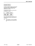
[0107] The initialiZe HW section con?gures the custom
features. An event timer 0 is used to read the loW going pulses
of PRX:
trigger. Again, this only demonstrates one possible use of the
trigger device.
[0101]
Measurements are taken on prototype l and deliv
ered to prototype 2 for processing. The key functionality of
prototype l is that it produces a pulse Width modulated
(PWM) signal every 16 milliseconds that corresponds to
re?ected intensity of an object. On prototype 2, the processor
has a built-in function to read PWM signals. This built-in
function alloWs a neW sample to be stored every 16 ms that
corresponds to the intensity of the re?ection.
[0102] Processing on prototype 2 happens in three phases.
The ?rst phase is to average the data so that measurement
noise is reduced. Stage tWo is the trigger algorithm. Before
entering an active triggering state, a target is validated only
after the object is determined to be static.At this point, thresh
olds are established for the target. Upon entering the active
triggering state, the thresholds are used to determine Whether
the motion is considered to be a valid trigger condition. The
third stage is non-critical determination of hoW to use the
trigger condition. In this case, volume is determined by the
amplitude of the measurement motion. A trigger event plays
a pre-recorded sound that sounds like a drum.
SoftWare4OvervieW
[0103]
Functionally of the hardWare is determined by soft
Ware loaded on the system. There are tWo parts of the system
that are controlled by softWare running on hardWare proces
sors: C8051F930 processor and ADSP-2l065L processor. In
this case, functionally Was broken up into items on tWo pro
cessors. This is done for convenience as the tWo hardWare
modules used naturally had separate abilities that combined
to produce a Working system.
IR Sensor Processing
[0104]
This processing takes place on C8051F930 (U1) of
the IR Slider demo unit. The softWare is not modi?ed from the
vendor de?nition. IR pulses are generated every 16 ms. Pres
ence of an object is measured by the loW going output pulse of
PRX. Active loW pulse Width is inversely proportional to the
distance to the re?ection of the IR from the object. (A small
reading means that the object is farther aWay than a object
With a larger reading.) IR is emitted during the pulse caption
time by Ul.
asrn(“BIT SET IMASK TMZLI;\
BIT CLR MODE2 INTiHIO l INTiHIlf’);
asm(“BIT CLR MODE2 PWMOUTO;”); /* Set pin to input */
asm(“BIT SET MODE2 PULSEiHIOf’); /* l to 0 transition */
asrn(“BIT CLR MODE2 PERIODiCNTlf’); /* Intr Width count */
asm(“BIT SET MODE2 TIMENO;”); /* Enable timer */
[0108]
IR Slider processes tWo channels by emitting With
tWo different sources and uses time multiplexing With a single
detector. In the 16 ms period, ?ve measurements are made: 2
from single source diodes, and three custom measurements.
Each emitter period occurs for less than 2.5 ms. The ?rst
measurement is made from D1 :D1 is the emitter used for the
tap sensing algorithm. As the ?rst ?ve 2.5 ms measurements
use pulsing patterns, there is a non-pulsed time of 3.5 ms (16
ms-2.5><5 ms). Measuring this non-pulsed time synchronizes
the sensor reading to the ?rst of ?ve pulsed patterns. Subse
quently, the circular buffer is ?lled With every ?fth reading.
This corresponds to a single emitter/ detector every 16 ms.
The primary algorithm reads the circular buffer every time a
neW sample is read. There are tWo modes of operation: active
and inactive. Inactive operation is When there is not enough
signal level for a good measurement. This is a setting based on
the position of the IR Slider. When the IR Slider is facing the
?oor approximately 4 .5 inches above the ground at 30 degrees
tilt from a normal orientation, a value of 0x3500 can be used.
When actively processing samples, thresholds are used to set
the degree of tap response.
[0109] A 64-sample average is used set the threshold. From
the most recent 64 samples, the highest, loWest, and average
values are found. If the high and loW values are Within 2
percent of the average, the threshold is set to (high-loW) times
2.
[0110] Incoming data is monitored to determine When a tap
occurs. Both monotonic increasing and decreasing input data
is measured. A monotonic decreasing input in Which (high
loW) is greater than the threshold calculated above Will cause
a trigger event.
[0111] A non-critical feature of a trigger described above is
a drum pedal application is that the trigger initiates a sound
sample. The sound sample produces sound reproduction of a
pre-recorded base drum being stuck by a mallet.
Aug. 1,2013
US 2013/0194030 A1
Visual LED Processing
ing” should be interpreted as referring to elements, compo
[0112] An LED is turned ON When an object is not
detected.
nents, or steps in a non-exclusive manner, indicating that the
referenced elements, components, or steps may be present, or
utiliZed, or combined With other elements, components, or
Appendix
[0113]
[0114]
IR Slider Schematic
EZ-DSP Schematic
Abbreviations
[0115]
COTS Commercial Off-the-shelf Hardware
[0116] DSP Digital signal processor
[0117]
IF Infrared
[0118] LED Light emitting diode
[0119] OEM Original Equipment Manufacture
[0120] PWM Pulse Width modulation
[0121] Many alterations and modi?cations may be made by
those having ordinary skill in the art Without departing from
the spirit and scope of the invention. Therefore, it must be
understood that the illustrated embodiment has been set forth
only for the purposes of example and that it should not be
taken as limiting the invention as de?ned by the folloWing
claims. For example, notWithstanding the fact that the ele
steps that are not expressly referenced. Insub stantial changes
from the claimed subject matter as vieWed by a person With
ordinary skill in the art, noW knoWn or later devised, are
expressly contemplated as being equivalent Within the scope
of the claims. Therefore, obvious substitutions noW or later
knoWn to one With ordinary skill in the art are de?ned to be
Within the scope of the de?ned elements. The claims are thus
to be understood to include What is speci?cally illustrated and
described above, What is conceptually equivalent, What can be
obviously substituted and also What essentially incorporates
the essential idea of the invention. In addition, Where the
speci?cation and claims refer to at least one of something
selected from the group consisting of A, B, C . . . and N, the
text should be interpreted as requiring only one element from
the group, not A plus N, or B plus N, etc.
What is claimed is:
1. A system that sends a command signal to a controlled
device, the system comprising:
ments of a claim are set forth beloW in a certain combination,
a radiation source that emits radiation to a detection region;
it must be expressly understood that the invention includes
other combinations of feWer, more or different elements,
a detector that detects re?ected radiation based on the
not only in the sense of their commonly de?ned meanings, but
emitted radiation from the radiation source, Wherein the
re?ected radiation is the emitted radiation that is
re?ected off of an object Within the detection region;
a processing device that is coupled to the detector to receive
electrical signals based on the detected re?ected radia
tion and to process the electrical signal into a processed
to include by special de?nition in this speci?cation structure,
data, Wherein the processing device send the command
Which are disclosed herein even When not initially claimed in
such combinations.
[0122]
The Words used in this speci?cation to describe the
invention and its various embodiments are to be understood
material or acts beyond the scope of the commonly de?ned
signal to the controlled device that controls at least one
meanings. Thus if an element can be understood in the context
of this speci?cation as including more than one meaning, then
its use in a claim must be understood as being generic to all
feature of the controlled device;
Wherein the command signal is sent When the processed
data matches With a predetermined triggering value; and
possible meanings supported by the speci?cation and by the
Word itself.
[0123] The de?nitions of the Words or elements of the fol
loWing claims therefore include not only the combination of
elements Which are literally set forth, but all equivalent struc
ture, material or acts for performing substantially the same
function in substantially the same Way to obtain substantially
the same result. In this sense it is therefore contemplated that
an equivalent substitution of tWo or more elements may be
made for any one of the elements in the claims beloW or that
a single element may be substituted for tWo or more elements
in a claim. Although elements may be described above as
acting in certain combinations and even initially claimed as
such, it is to be expressly understood that one or more ele
ments from a claimed combination can in some cases be
excised from the combination and that the claimed combina
tion may be directed to a subcombination or variation of a
subcombination.
Wherein the predetermined triggering value comprises the
traveling path of said moving object traveling from a
point A to a point B, and returning back to said point A,
Wherein said point A is located
a) on a contact surface of a stationary object Within the
detection region; or
b) mid-air Within the detection region, Wherein the detec
tion region is a 3-dimensional space.
2. The system as recited in claim 1, Wherein the system is
a controlling device that controls the controlled device,
Wherein the controlling controlled device is an on/ off sWitch,
or a gradient controller (e.g. volume/?oW control), and
Wherein the command is one selected from a group consisting
of an on command, an off command, an increase in relative
quantity command, a decrease in relative quantity command,
an increase in relative intensity, a decrease in relative inten
sensing sWitch have been disclosed. It should be apparent,
sity, and a mode-changing command.
3. The system as recited in claim 2, Wherein the predeter
hoWever, to those skilled in the art that many more modi?ca
mined triggering value is at least one selected from the group
tions besides those already described are possible Without
departing from the inventive concepts herein. The inventive
subject matter, therefore, is not to be restricted except in the
relative velocity, a strength indication, a distance, a pattern of
spirit of the appended claims. Moreover, in interpreting both
Wherein the processed data is at least one selected from the
[0124] Thus, speci?c embodiments and applications of tap
the speci?cation and the claims, all terms should be inter
preted in the broadest possible manner consistent With the
context. In particular, the terms “comprises” and “compris
consisting of a light intensity difference, a traveling path, a
light changes; and
group consisting of a light intensity difference, a travel
ing path, a relative velocity, a strength indication, a dis
tance, and a pattern of light changes.