1
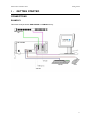
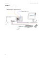
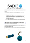
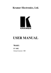
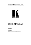
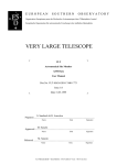
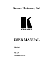
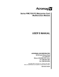
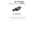
WELCOME!
Congratulations on your purchase of a SADiE product; part of a range making up the most powerful
hard disk editing systems in the world. These products are the result of over 15 years experience in
the industry listening to our customers, taking on board their ideas, and providing for their needs. Our
ethos of close customer contact, and free technical support and software upgrades has meant that
customers not only buy a system but also make an investment that will reap dividends as the software
expands. We feel confident that you will find using this system very enjoyable and hope that our
products will be part of your production system for many years to come.
As you take your system out of the box for the first time it is worth spending just a few moments
reading this document, as it will help you to set up your system effectively and efficiently. Inside you’ll
find a complete packing list, help with connecting up your system and our troubleshooting guide to
help overcome any initial problems.
HARDWARE AND SOFTWARE INSTALLATION
NOTE: A complete packing list for your new equipment is enclosed. Upon unpacking the equipment,
please ensure that all the items listed are present. If you think that anything may be missing or has
arrived in a damaged condition, please contact your supplier immediately
SADiE digital audio workstation systems can be provided in a number of different configurations. The
number and type of audio cards will all make a difference to how everything connects together. Most
SADiE systems are provided as “Turnkey” packages, where the required options will be provided fitted
into a SADiE Rack PC, with software pre-installed, configured, and ready to go. Alternatively you may
have ordered just the audio cards and other options, and intend to install the hardware and software
yourself.
The first “Getting Started” section of this Installation Guide describes how to connect up a Turnkey
system to its peripherals and breakout boxes, with some diagrams of example set-ups. The “Technical
Reference” section will describe installation and specifications of individual cards and items, for
reference purposes or for those that have purchased cards and software only.
This document provides information on SADiE systems based on PCI cards, i.e. PCM4, PCM8, PCMH8, and PCM-H16.
Getting Started
Connections...........................................................................................................................................1:1
Getting Started with SADiE6 .................................................................................................................1:5
SADiE on the Internet ...........................................................................................................................1:6
Technical Reference
PCM4, PCM8, PCM-H8 & PCM-H16 ....................................................................................................2:1
Installing SADiE6 Software ...................................................................................................................3:1
SADiE Hardware Control Panels ..........................................................................................................4:1
PCI CAT Timecode and Machine Control Card ....................................................................................5:1
Technical Specifications
PCM4 & PCM8 – I/P and O/P Specifications ........................................................................................6:1
Conformity Statements ..........................................................................................................................6:6
PCM Hardware Installation Guide
1-
Getting Started
GETTING STARTED
CONNECTIONS
EXAMPLE 1
This shows a simple 8 track SADiE PCM8 or PCM-H8 turnkey.
1:1
Getting Started
EXAMPLE 2
This shows a SADiE PCM4 turnkey.
1:2
PCM Hardware Installation Guide
PCM Hardware Installation Guide
Getting Started
EXAMPLE 3
This shows a 16-track SADiE PCM8 turnkey with options:
Balanced analogue I/O option – note that the 8in/8out XLR connectors on this replace the
unbalanced jacks on the standard breakout panel. The “800B” balanced breakout panel connects
directly to the 44-way connector on the back of the PCM8 card, and provides a “Y-lead” connection
onto which the standard “800” breakout box connects.
rd
NOTE: The diagram shows only one pair of breakout boxes connected. The second card (and 3 and
th
4 for larger systems) will connect identically.
Note also that the provided DC power supply connects to the balanced panel only. The unbalanced
“800” panel has a connector for a power supply, but this is used only when it is used in conjunction
with an optional Apogee AD-8000 24-bit AD/DA converter.
Hardware controller pair (Jog and Fader panel) – connect usually to 9-pin Port 1 on the standard
“800” breakout box. Note that the undersides of both panels are printed with details of exactly how to
connect the cables.
1:3
Getting Started
PCM Hardware Installation Guide
A CLOSER LOOK AT THE PC CARDS
Depending on the configuration of the system there are a number of different connectors you may see
on the back panel of your computer. The drawings below should help you identify the cards in your
system (you will NOT have all of these!). In a Turnkey system, the cards will also be identified by a
label below the card slot at the rear of the main SADiE rack PC.
PCM8, PCM-H8 or PCM-H16 digital processor card
Purpose:
1
Female 44-way D-type
connector
The “workhorse” of the SADiE system. Provides
digital audio processing. A PCM8 or PCM-H8
occupies one PCI slot; the PCM-H16 uses the
same long PCI card, however includes a second I/O
daughter card which will then break out of the rear
of the Pc in the next slot.
Connectors
1.
To Breakout box(es)
PCM4 digital processing card
2
1
Purpose:
The “workhorse” of the SADiE system. Provides
digital audio processing.
Connectors
PCM4 occupies 2 x PC slots: one for the card, and
the other for the breakout lead for digital I/O (i.e.
connector number 3). The breakout leads are
colour coded to match the colour label next to each
multi-pin connector.
1.
2.
3.
RED – analogue in and out 1&2
YELLOW – analogue in and out 3&4
BLUE – digital in and out 1,2,3 & 4
Three female 15-way
D-type connectors
3
PCI CAT Card
2
3
1
Purpose:
To allow 9-pin machine control of compatible
devices and provide SMPTE Timecode support.
Connectors
Male 25-way D-type
connector
1:4
1.
2.
3.
To breakout box (PCM8) or 9-pin breakout cable
(PCM4)
Video Ref In
Video Ref Out
PCM Hardware Installation Guide
Getting Started
GETTING STARTED WITH SADiE6
If you have purchased a new SADiE system you will find a SADiE6 software manual in the package.
Please refer to Chapter 1 of the software manual, entitled “Getting Started”, which will take introduce
you to the following areas of the system:
•
A general introduction to Digital Audio Editing
•
An introduction to SADiE systems
•
SADiE basics (Using Help, User Management, Starting SADiE, The Display, On-screen Help)
•
Tutorial (Connections, Recording, Playing and Arranging the EDL, Saving, Editing, Mixing)
HELP
A full on-line help file is available within the SADiE6 software. To access it, go to the “Help” menu at
the top of the SADiE screen and select “Help on SADiE6”.
The Help File is set out in the following chapters:
•
Getting Started explains the concepts behind the system and the terminology used and gives
you a quick guide to getting your system working for you. The Tutorial provides a step-by-step
guide to editing the audio provided. We recommend that you follow this in order to save time
later.
•
Recording
•
Using the Playlist
•
Arranging an EDL
•
Editing
•
Mixing
•
File Management
•
Specific Applications contains notes on operations relevant to more specialised areas of work.
For example: CD pre-mastering; Auto-conforming for video post-production and syncing film
rushes.
•
Customising SADiE explains the settings you can change to affect the way the system works
or appears on the screen.
1:5
Getting Started
PCM Hardware Installation Guide
SADiE ON THE INTERNET
WEB SITES AND FAQ PAGES
The SADiE website is at http://www.sadie.com
On this site you can find new product information, customer support information, FAQ lists, software
download areas, contact and supplier information, news, company details, press releases, and details
of forthcoming trade shows.
SADiE USER FORUM ON THE INTERNET
There is an independently run SADiE user forum on the Internet.
Once you’ve registered for the SADiE Web board you can view new and old messages online.
Additionally you can “subscribe” to any or all of the forums on the Web board, and these messages
will be e-mailed to you directly.
1.
To Register for the SADiE Web board:
a. Using a web browser go to:
http://webbd.nls.net/webboard/wbpx.dll/~SADiE
b. At this “front-door” you can register as a New User. Once you’ve applied, you will have to wait
for a while and the Web board administrators will e-mail you a reply including your own
password for the site.
2.
Once you have received your password, return to the site and log-on using your e-mail address
and the password provided. You will be able to access messages in three different ways:
a. Directly on the Web board, where you have the ability to view ALL messages that have been
posted. The Web board also has search facilities, so you can search to see if particular topics
have already been discussed
b. You can choose to receive new messages and reply to them via e-mail. Press the “MORE”
button, then “Mailing Lists”, where you can sign up to receive messages from particular
conferences via e-mail.
c.
Via a Newsreader. Point the Newsreader at webbd.nls.net and you will be offered the sections
you have access to. These may include the “Pro-Audio” and “Mastering” boards; once you
have access to the SADiE Web board you can also access the other areas hosted by the Web
board.
The Web board itself has further details of the facilities it offers under “Help”.
1:6
PCM Hardware Installation Guide
2-
Hardware Installation
HARDWARE INSTALLATION
SADiE HARDWARE PLATFORMS
There are a number of different PCM Series 6 hardware platforms on which the SADiE6 Software
System can run; this document describes operation of the “TNG3” model processors that are based
around PCI cards - PCM4, PCM8, PCM-H8 and PCM-H16. All offer similar facilities but with differing
capabilities. All are PC plug-in cards, and are based on a similar design. The installation of them is
similar and so this document will describe the installation by referring to them generically as “SADiE”
cards, and only describing individual cards if their installation differs from the norm.
The PCM Series 6 cards are full-length PCI plug-in cards.
The PCM8 card gives 8 channels of audio input and output which are connected via a multi-way
connector to the SADIE 800 and 800B breakout boxes. The PCM8 uses 2 DSPs
The PCM-H8 card has the same audio capabilities and connections as the PCM8, but the processor
card is more powerful and utilises 5 DSPs for audio processing.
The PCM-H16 card is the same as the PCM-H8, but whereas the PCM-H8 has a single daughter card
that provides 8 channels of I/O, the PCM-H16 has an additional “piggy-back” daughter card to provide
a further 8 channels of I/O. The second daughter-card uses the PC slot next to the main card, and so
of all these PCI SADiE cards, the PCM-H16 is the only one that occupies two PCI slots.
PCM4 is similar to the PCM8 card. PCM4 provides 4 channels of audio I/O. These are connected via
three 15-way D-Type connectors, which connect to XLR cable looms. Two of the 15-way connectors
are on the PCM4 card itself, the other one is on a “flying” lead as described below.
INSTALLING THE SADiE CARD(S) INTO YOUR OWN PC
It is a relatively simple task to install the SADiE hardware into your PC. However, it does involve
taking the top off your PC and physically inserting the SADiE card(s). If you are unhappy delving into
the innards of your PC then we would advise you to get the help of a friend who is experienced in this
type of operation. In any case you will need to refer to your PC's User Manual for details on how to
gain access to the expansion card slots.
NOTE: SADiE cannot guarantee that the SADiE card or software will operate correctly in your PC. If
you have any difficulties making SADiE operate, please contact your supplier or SADiE directly who
will be happy to quote for attempting to make it work with your equipment, or for supplying a “turnkey”
solution for you.
INSTALLING THE SADiE CARD
Be sure that power is removed before opening your PC and inserting (or removing) the expansion
cards. Some PC’s have an On/Off switch on the front of the unit, which does not necessarily remove
ALL power! For safety, remove all power cables completely. For sake of ease and safety, you should
disconnect the mouse, keyboard, monitor and any other cables at the back of the PC.
The SADiE cards are full-length PCI cards, so you’ll need to identify one or more (depending how
many cards you are fitting) PCI expansion slots in your computer into which they can fit. Pay attention
to ensuring that components on the PC motherboard are not in the way of the card when it is inserted.
If such a component should come into contact with the SADiE board during operation, it may destroy
both the card and your computer. Remove the blanking plate from the slot you have decided to use.
If you are installing more than one PCM8 card for a “multi-card” system, the supplied leads will
probably dictate that the cards should be in adjacent PCI slots.
NOTE: It is imperative that your PC has a sufficient flow of cooling air to keep the SADiE boards at
their proper operating temperature. Multiple card systems will generate more heat, and so particular
care should be taken in these cases. If in doubt, you can purchase a specially made, rack-mount PC
from SADiE.
2:1
Hardware Installation
PCM Hardware Installation Guide
If in doubt about fitting the cards into your PC refer to your PC's Installation Guide, but pay particular
attention to the following points:
STATIC PRECAUTIONS
The SADiE cards and other parts of your system are easily damaged by static electricity; do not
remove the cards from their protective packaging until you have observed all static safety precautions.
PLUG AND PLAY (PNP)
You do not need to set any base address links or switches on the card prior to installation. The
software installation is detailed in the next chapter.
INSERTING THE CARD
Place the card(s) into the slot(s). Take care that the blue plastic bracket on the card enters the correct
card guide at the front of the PC and that the edge connector at the base of the card enters the
receiving connector on the PC motherboard. You will have to use firm, but not excessive, pressure to
insert the card fully. Once the card is properly in the slot, replace the screw that was holding the blank
plate. This is the only physical restraint on the card and it protects the card and the PC from damage
caused by the card moving when you plug a cable into one of its rear panel connectors or during
transport. Try to avoid positioning the cables so that they block air holes or fans, as this will affect
cooling efficiency.
SPECIAL REQUIREMENTS FOR MULTI-CARD SYSTEMS:Although it is possible to connect PCM8 cards as multiple cards, with the availability of the PCM-H64
system, new systems will not be supplied in this way. Mention of multi-card systems in this document
remains only for legacy support.
One card will be a "Master" card and the others will be designated "Slave" usually by the letter S by
the side of the serial number sticker. There is no other physical difference between the cards, although
they are electrically different.
When placing more than two PCM8 cards in a PC, the Master card MUST be on the "outside", thus
the order of slots in the PC can be Master, Slave, Slave, Slave, or S, S, S, M, but not S,S,M,S, or
S,M,S,S.
INTERCONNECTIONS
Digital Audio cable (PCM4 only) – PCM4 is supplied with three Audio I/O looms for analogue and
digital audio inputs and outputs. For details of the connection of these see below. At this stage you will
need to consider whether you require digital audio connections to the PCM4. This is sent via the
supplied 16way to 15way “D-type” cable, that has it’s own PC fixing plate attached. For digital audio
I/O to be possible, you will need to find another back-plane slot (or some other hole in the back of the
PC) to take the 15-way D-type connector, and connect the dual-in-line connector on the other end
onto connector J4 on the top edge of the PCM4 card.
PCI CAT card - You may have an RS422/timecode card. This is a smaller PCI card, and the PCI CAT
is an optional extra card for PCM Series 5 kit to provide timecode and 9-pin machine control, or for
connecting the Hardware Controller option. For Information on connecting the PCI CAT card please
see the PCI CAT Section of this guide.
Multi-card interconnections - An interconnect cable will be supplied for multi-card systems,
consisting of the appropriate number of 10-way IDC connectors. This connects to the 10-way
connector J2, which is on the top of each PCM8 card (just behind the expansion board). The cards
should be fitted in a Master-slave-slave-slave order, such that the Master card is on one end. Doublecheck the cables. Check that there are no trapped cables, everything is firmly connected, and in the
correct orientation. Replace the lid of the computer.
Reconnect the cables you disconnected at the start of this procedure and connect any cables that you
want to run to the new cards.
2:2
PCM Hardware Installation Guide
Hardware Installation
You’re almost ready to power up the PC. What happens next depends on which operating system you
are using, and this is described in the next chapter.
CONNECTING THE AUDIO I/O
PCM8 & PCM-H8
Each PCM8 card will have one or two breakout boxes, depending on whether the analogue balanced
option has been purchased. The standard “800” breakout box has 4 male and 4 female XLR’s on the
face for AES/EBU in and out, plus 16 mono ¼” jacks for unbalanced analogue in and out. The rear of
the “800” breakout box has connections for the CAT card, 9-pin ports and LTC in and out. The optional
“800B” breakout box has 8 male and 8 female XLR’s for balanced analogue I/O.
There are some diagrams in the Connections section above, which show how to connect the breakout
boxes. If only an “800” breakout box is supplied, its captive lead connects directly to the rear of the
SADiE card. If both breakout boxes are provided, then the “800B” 44-way male D-type connects
directly to the SADiE card, and the “800” connects to the female 44-way D-type connector which is
attached near the main, male 44-way connector of the “800B”.
In either case, the PCI CAT card connects to rear of the “800” breakout box via a 25-way cable. Both
ends use the same sex connector, but there is a difference: one end will be labelled “BOB” which
connects onto the “800” breakout box, and the other will be labelled “CAT” which obviously connects
onto the mating connector on the PCI CAT card.
PCM-H16
The PCM-H16 card is the same as a PCM8-H8, except that TWO daughter boards for audio I/O are
provided, and thus TWO sets of 800 and 800B break out boxes may be connected to provide 16 x
AES and Analog I/O.
In this case the CAT cable can be connected to either of the 800 break out boxes.
PCM4
Three audio looms have been provided for connection of audio inputs and outputs to PCM4. These
will need to be connected to the three 15-way D-type connectors: two on the back of the PCM4 card,
the third (for AES/EBU digital connections) is on the “flying” lead that was attached to J4 of the PCM4
as above.
The leads have colour-coded shells on the 15-way connector, which match the insert of the D-type
connectors on the PCM4 and flying lead. All cards have a label on the card to identify the colour.
All leads have four XLR connectors (2 male 2 female) on one end and a 15-way male D-type
connector at the other end.
BLUE cable
This is for AES/EBU digital connections. The 15-way connector attaches to the
Blue 15-way D-type on the “flying” lead attached to J4 of the PCM4.
RED cable
This is for Analogue Inputs and Outputs 1 and 2. The 15-way connector attaches to
the Red 15-way D-type, which is the LOWER of the two on the back of the PCM4
card.
YELLOW cable
This is for Analogue Inputs and Outputs 3 and 4. The 15-way connector attaches to
the Yellow 15-way D-type, which is the UPPER of the two on the back of the PCM4
card.
The XLR’s on all three cables are labelled appropriately. Male XLR’s will provide outputs and Females
inputs in all cases.
2:3
PCM Hardware Installation Guide
3-
Installing Software
INSTALLING SOFTWARE
INSTALLING DRIVER SOFTWARE
You will need to log on as an administrator in order to install SADiE.
When you first boot the PC after the SADiE hardware has been inserted in or connected via USB,
Windows™ will notice the hardware change and offer to “Plug and Play” the hardware and search for
a driver.
Windows™ will report "Found new hardware – multimedia controller… Welcome to the Found new
hardware wizard….". At this point you should press cancel in order to halt the plug and play.
Windows™ will have installed a generic multi-media controller device at the moment, but installing the
SADiE6 application software will resolve this and install the correct hardware driver.
INSTALLING SADIE5 SOFTWARE
You will have been provided with the installer for SADiE6. This is either on the standard “V6
SOFTWARE INSTALLATION DISK” with the blue “6” logo, or else it may have been downloaded from
the SADiE Web site.
INSTALLING FROM THE CD
On inserting the V6 SOFTWARE INSTALLATION DISK, if you wait a short while, the “Welcome to
SADiE Version 6” menu will appear.
If this doesn’t happen, autorun may have been turned off on your CD drive; the quickest alternative
way to get to this menu is to:
Press the Windows™ "Start" button; select "Run" and type z:\autorun (where in this example z: is the
letter of your CD drive). The “Welcome” menu will now appear.
To install the SADiE6 software, select your hardware, then Install SADiE v6 Software and follow the
installer instructions thereafter.
A SADiE6 icon will appear on your desktop. Double-click this to run the SADiE software.
DOWNLOADING SOFTWARE FROM THE INTERNET
The most recent version of SADiE software is available for download on the SADiE World Wide Web
page. It can be found at http://www.SADiE.com
On the home page choose Support and then the Downloads link.
Then download the current version of SADiE 6 Software.
The download page offers you the SADiE software disks along with other downloads: release notes,
installation notes, etc. and installers for plug-ins.
To install the SADiE6 software, you will either be offered the chance to RUN the installer, straight after
downloading it, or else you will need to navigate to the location on your hard drive that it was
downloaded to, and double click on the installer file.
Then follow the instructions on the screen, as above a shortcut will be placed on your desktop – run
this to run the SADiE application.
UPDATING THE SOFTWARE
You may be downloading the SADiE6 software installer in order to update the software to a newer
version.
Under normal circumstances, if you are updating to a newer version of software, then running the new
installer will automatically uninstall the old version first, and then will install the new application files.
3:1
Installing Software
PCM Hardware Installation Guide
There are sometimes occasions where this is not possible – if you updating from a very old version or
perhaps an intermediate beta-test version, then the software itself may tell you that you must manually
uninstall first. If this happens:•
Press the Start button, and choose Control Panel
•
Select Add or Remove Programs
•
Scroll down to find the entry for “SADiE Software”, select it, and press the Remove button
•
Wait until that process has completed, then you can proceed to installing the new version of
software.
Note that uninstalling software does not affect any projects you have created, nor will it change any
settings for the program; it merely removes the application files.
INSTALLING PLUG-INS
Software options and plug-ins come in two differing forms – either:a) they are part of the SADiE software and only require to be authorised, or
b) they are third-party options which require an extra installer.
Internal Options / SPW files
The majority of the available options fall into the first category, and you will be supplied with an SPW
file which may contain one or more authorisations codes.
With a new system, any SPW files will be in the root directory of the supplied installation CD. On
starting the SADIE software for the first time, you will be asked to supply this SPW and you should
navigate to the CD when asked by the software.
To install SPW files at other times:
•
Run SADIE6
•
From the File menu, select “Install Plug-in Options”
•
Then navigate to the supplied SPW file; the software will check the authorisations and report.
•
Then close SADiE and re-start the software before you use the plug-ins.
Other plug-in Installers
Currently (Januaray 2011) the following options require a separate installer :
•
All Cedar options (De-click96, De-Crackle96, De-Noise96, De-Thump96 and Retouch),
•
Soundfield Surround Zone
•
ProTools5 Interchange
•
OMF Interchange
With a new system, again, the authorisations for these will be in the root directory of the supplied
software CD. The menus on the CD can be navigated to run the plug-in installer, and any
authorisation codes found on the CD will install automatically.
If you are downloading the plug-in installer, it will come in one of two forms – a ZIP file or an EXE.
The ProTools5 and OMF Interchange plug-ins are downloaded as zipped sets of files which must be
extracted first before the installer can be run.
The others are self-extracting EXE files which will start installing as you double-click to run them.
If the plug-in installer asks for a password, it will have been supplied to you in a file called PWD??.TXT
– open this in Notepad, select the string of random characters, right click and copy to paste. Then
when the installer asks, paste this string into the dialog box.
If the installer doesn’t ask for a password, it will have found it automatically (if the PWD??.TXT is in the
root directory of the disk from which the installer is running, it will find the code).
3:2
PCM Hardware Installation Guide
Installing Software
INSTALLATION TROUBLESHOOTING:
Every PC configuration will be different, so it’s difficult to give hard and fast rules about every possible
situation that may occur. Some guidelines can be offered however. If you are not confident
troubleshooting the PC installation or are unsure with any of the terms used in this section then you
should consult someone who is, or contact SADiE customer support.
You will need to be logged on as an Administrator to install SADiE software and fault find an
installation.
It is quite likely that modern operating systems will be able allocate the PC’s resources in such a way
as to avoid conflicts, however conflicts can still occur. The most likely conflict is either one of IRQ or
“interrupt” or “address” a.k.a. “Port address” a.k.a. “I/O address”.
PCI cards such as the SADiE cards will have the IRQ and I/O address allocated by the operating
system. The I/O address will be unique, but (in theory) IRQ’s can be shared. The SADiE cards are
happy enough sharing an IRQ with each other or another PCI device. However, some other PCI
devices may not be so happy to do this. Therefore, if in Device Manager, you see another device
sharing an IRQ with the SADiE audio card, this is not necessarily a problem. However, because a
shared IRQ is Windows™-legal and the IRQ’s are allocated by Windows™, if there is a problem with
the sharing of IRQ separating the devices can be very difficult. Sometimes a PC will allocate a
particular IRQ to a particular PCI slot and thus changing the slot may cause the device to “jump” to
another IRQ.
3:3
PCM Hardware Installation Guide
4-
Hardware Control Panels
HARDWARE CONTROL PANELS
GENERAL
The SADiE Hardware Controllers consist of two units that have mechanical cross sections similar to
most common PC keyboards. The larger fader panel has eight assignable touch-sensitive motorised
faders. The jog unit has one fader and a jog or shuttle wheel in the centre.
The units can free stand and be arranged to suit the user. A special power supply and RS422 serial
interface card (the PCI CAT card) are also needed.
INSTALLATION
The serial interface card must be installed inside the PC. See the PCI CAT installation sheet later in
this document for details.
CABLE CONNECTIONS
Cable and power supply connection is detailed on the underside of both the jog and fader panels. See
also the Connection diagrams earlier in this booklet.
SOFTWARE INSTALLATION
To turn on the Hardware Controllers inside the SADiE software:
•
Under the “View” menu select “Setup Window”
•
Choose the “9-pin Channels” page on the left side of this window
•
From the drop-down list at the side of the 9-pin port to which the controllers are connected,
select “Hardware Controller”. The lights on the Hardware Controller will change and they will
now be operational.
Subsequently, starting SADiE will automatically search for the controllers on that 9-pin channel, and
initialise them if they are there. If however, the controllers are switched off when SADiE boots, you will
see an error message. You’ll have to power them up, and then initialise them again in the “9-pin
Setup” page.
POWER SUPPLY
This is a fully certificated custom unit that must be supplied by SADiE. A label on its underside
identifies it. Connect this unit to the local mains via its embedded IEC connector. Line voltage
selection is automatic. There are no user adjustments. Allow air to circulate around this power supply
for cooling purposes.
USAGE
There are no on-off power switches on any unit. To switch off (or force a reset) the power supply must
be disconnected from the mains supply
When power is applied, the fader and jog panels should display their ROM version number (internal
control software) on their LED indicators. This display will change when SADiE gains control via the
serial link
The SADiE software User Manual and Help file give details throughout of hardware controller
operation, and also contains a list of the keys and their functions.
4:1
PCM Hardware Installation Guide
5-
PCI CAT
PCI CAT
INSTALLING A PCI CAT IN A PC
If you have purchased your PCI CAT card as part of a SADiE Turnkey unit then it will have already
been installed into the system. Otherwise this section will lead you through installing the PCI CAT card
into your system. This installation should only be carried out by a suitably qualified person. Do not
remove the PCI CAT card from its protective packaging until indicated by these instructions. Please
also observe full static safety precautions whilst handling the PCI CAT card, or touching any of the
internal components of your computer.
Ensure that the computer is switched off. If your computer has a power switch on the power supply
unit (near to where the mains lead is connected), this should also be switched to the off position and
the power cable removed.
•
Remove the computer’s lid.
•
Insert the PCI CAT card into a spare PCI slot of the computer motherboard.
•
Connect the PCI CAT card to the PCM4 or PCM8 card with the PCI CAT SYNC lead. The 10way connector attaches to the PCI CAT card by way of the 10-way box header on the PCI
CAT card labelled SYNC. Ensure that the wires are at the rear of the connector (this is the
end nearest to the MIDI connector).
•
On the SADiE TNG3 card, the two paired cables connect to LK1 and LK2 - it doesn't matter
which colour connects to which header as these are auto-sensing but you the black cable of
each pair must be towards the top of the TNG3 card.
•
Screw the card into position and replace the computer’s lid.
•
If you are happy that everything has been reconnected correctly, connect the power and start
the system up.
•
Once Windows has started, Plug and Play will recognise the new CAT card. Be sure to
Cancel out of this.
•
Then install the SADiE software again; this will load the driver for the Cat card automatically.
See Installing Software above for details on how to install the SADIE6 software.
5:1
PCM Hardware Installation Guide
6-
Input/output specifications
INPUT/OUTPUT SPECIFICATIONS
GENERAL
Figures apply for 32 kHz, 44.1 kHz, and 48 kHz operating frequencies and, in the case of digital I/O,
their multiples. They do not necessarily apply for minus 0.1%, chase lock, or varispeed rates.
INPUTS
DIGITAL INPUTS
The PCM8 and PCM-H8 cards support four two-channel digital inputs1. A separate reference input is
available for clock synchronisation purposes.
The PCM-H16 cards supports eight two-channel digital inputs2. A separate reference input is available
for clock synchronisation purposes on the first daughter-card.
PCM4 cards support two two-channel digital inputs at up to 96 kHz sampling frequency.
AES INPUTS
XLR female connectors3: transformer balanced and isolated.
•
Accept levels between 500mV and 10V peak-to-peak.
•
Accept digital protocols to S/PDIF (consumer, IEC 958) or AES (professional AES3-1992)
format, 32 – 48 kHz +10%
•
Impedance: 110Ω
•
No equalisation fitted.
DIGITAL REFERENCE INPUT
XLR female connector: transformer balanced and isolated.
•
Accepts levels between 500mV and 10V peak-to-peak.
•
Impedance: 100Ω ± 10%
•
No equalisation fitted.
NOTE: The PCM8, PCM-H8 and PCM-H16 cards will support AES digital reference for
synchronisation purposes. They do not support “word-clock” or SDIF-2 synchronisation signals on
input or output.
All analogue XLR connectors are wired in the following order:
Pin 1
Ground
Pin 2
Positive, non-inverting “hot”
Pin 3
Negative, inverting, “cold”
1
Eight channels digital inputs up to 88.2/96kHz or four channels at 174.4/192kHz
Sixteen channels digital inputs up to 88.2/96kHz or eight channels at 174.4/192kHz
3
AES-3 pinout for digital audio XLR connectors.
2
6:1
Input/output specifications
PCM Hardware Installation Guide
ANALOGUE INPUTS4
The PCM8 and PCM-H8 cards support 8 channels of analogue input. These signals appear on type
“800” breakout box which is populated with ¼” mono jack connectors. Optionally a type “800B”
breakout box is available with female XLR connectors and electrically balanced receivers.
The PCM-H16 card supports 16 channels of analogue input. These signals appear on two type “800”
breakout boxes which are populated with ¼” mono jack connectors. Optionally type “800B” breakout
boxes are available with female XLR connectors and electrically balanced receivers.
The PCM4 card supports 4 channels of analogue input. These signals appear on XLR cable looms
supplied with the card.
•
•
Nominal Level for peak digital audio (sine wave):
o
800, unbalanced jacks +12dBu5
o
800B, balanced XLR
+12dBu
o
PCM4 balanced XLR
+18dBu
Conversion:
o
24-bit 64-times over-sampling delta sigma converters, one per channel, simultaneous
conversion, up to 96kHz sample rate.
•
Input impedance: > 10kΩ
•
Frequency response: 20Hz - 20kHz, +/- 0.5dB, AC coupled.
•
Total distortion and noise6 with 1kHz applied at peak level: better than 90dB
•
CMRR - > 80dB @ 50Hz
TIMECODE INPUT
XLR female located on back of type “800” breakout box. Electrically balanced
•
Level: -17dBu to +7dBu
•
Impedance: >10kΩ
VIDEO INPUT
BNC connector located on back of PCI CAT card.
•
PCI CAT card applies termination of 75Ω
•
Sync pulses should be 300mV when terminated in 75Ω
•
Two line vertical interval timecode can be read
OUTPUTS
DIGITAL OUTPUTS
The PCM8 and PCM-H8 cards provide four two-channel digital outputs7. The PCM-H16 provides eight
two-channel digital outputs8. PCM4 provides two two-channel digital outputs.
4
Onboard A to D converters do not operate faster than 96kHz sample rate
0 dBu = 0dBm in 600 Ω = 0.775 Vrms
Other levels are available by arrangement
6
S / (THD +N) 20Hz to 20kHz unweighted
7
Eight channels digital input at 88.2/96kHz or four channels at 174.4/192kHz
8
Sixteen channels digital input at 88.2/96kHz or eight channels at 174.4/192kHz
5
6:2
PCM Hardware Installation Guide
Input/output specifications
AES OUTPUTS
XLR 3-pin male connectors, transformer balanced and isolated.
•
Generates digital protocols to S/PDIF (consumer, IEC 958) or AES (professional AES3-1992)
format, 32 – 96 kHz +10%, depending on software selection.
•
Output level: 10V p-p (5V p-p when terminated in 110Ω)
•
Source impedance: 110Ω +/- 10%
•
Symbol jitter < 20ns p-p RMS
ANALOGUE OUTPUTS9
PCM8 and PCM-H8 support 8 channels of analogue output. These signals appear on the type “800”
breakout box which is populated with ¼” mono jack connectors. Optionally a type “800B” breakout box
is available with male XLR connectors and electrically balanced drivers.
PCM-H16 supports 16 channels of analogue output. These signals appear on two type “800” breakout
boxes which are populated with ¼” mono jack connectors. Optionally type “800B” breakout boxes are
available with male XLR connectors and electrically balanced drivers.
PCM4 supports 4 channels of analogue input. These signals appear on XLR cable looms supplied
with the card.
•
Level for peak digital audio (sine wave):
o
o
o
800, unbalanced jacks
800B, balanced XLR
PCM4 balanced XLR
+12dBu10
+12dBu
+18dBu
•
Conversion: 24-bit 64 times over-sampling delta sigma converters, one per channel,
simultaneous conversion, up to 96kHz sample rate.
•
Output impedance < 25Ω
•
Frequency response: 20Hz - 20kHz, +/- 0.5dB, DC coupled.
•
Total distortion and noise11 with 1kHz applied at peak level: better than 90dB.
TIMECODE OUTPUT
Electrically balanced XLR male connector:
•
Level: +3dBu
•
Impedance: 25Ω
SERIAL MACHINE CONTROL INTERFACE
Four channel of serial interface are provided via four 9-pin female D connectors on the back of the
type “800” breakout box.
•
RS-422 compatible signalling
•
Industry standard machine control pin out
VIDEO OUTPUT
BNC connector on CAT card
•
Source Impedance: 75Ω
9
On board D to A converters do not function faster than 96kHz sample rate
0 dBu = 0dBm in 600 Ω = 0.775 Vrms
Other levels are available by arrangement
11
S / (THD +N) 20Hz to 20kHz unweighted
10
6:3
Input/output specifications
PCM Hardware Installation Guide
E-E
Performance when operating E-E (Electronics to Electronics, i.e. input is processed via input
electronics then via output electronics without intervening recording or audio processing):
DIGITAL INPUT TO OUTPUT
•
Sample rate out is locked to sample rate in.
•
Output protocol is independent of input protocol, i.e. can convert AES to S/PDIF or vice versa.
•
User bits are not passed through system.
•
Output data equals input data, i.e. signal is unchanged (16 - 24 bit signals only, dithering off,
with both input and output selected to match the test data).
ANALOGUE PERFORMANCE, INPUT TO OUTPUT
•
Frequency response: 20 Hz – 20 kHz, +0.5 dB, AC coupled.
•
Total distortion and noise12 with 1 kHz applied at peak level: better than 90 dB below peak.
EMPHASIS
PCM Series 5 supports emphasis only in channel status sub-code.
RECORDING METHOD
No data compression is used. Recorded data is replayed unchanged if no processing is selected in
software.
POWER REQUIREMENTS (TURNKEY PCM SERIES 5 UNIT)
•
230 V or 13 +/- 10% , AC 50-60 Hz.
•
IEC line connector
•
Steady-state power requirement < 300 W
•
Fuse: 5 Amps (T)
COMPLIANCE
Case is CE marked:
Conforms to the following standards:
•
EN50081-1 (EN55022); 1995
•
EN50082-1 (EC 801-2,3,4); 1992
Following the provisions of the Low Voltage and EMC Council Directives:
12
6:4
•
73/23/EEC
•
89/336/EEC
S / (THD +N) 20Hz to 20kHz unweighted
PCM Hardware Installation Guide
Input/output specifications
MECHANICAL
•
•
•
SADiE turnkey: 19” rack mounting chassis. 4U.
o
Max dimensions: 485mm wide x 550mm deep x 180mm high.
o
Mass < 20 kg
Breakout box “800”: 19” rack mounting chassis 1U
o
Max dimensions: 485mm wide x 280mm deep x 89mm high.
o
Mass < 3kg
Breakout box “800B”: 19” rack mounting chassis 1U
o
Max dimensions: 485mm wide x 280mm deep x 89mm high.
o
Mass: < 3kg
6:5
Input/output specifications
PCM Hardware Installation Guide
CONFORMITY STATEMENTS
EUROPEAN COMMUNITY - CE
SADiE declares that its products conform to the following standards:
•
EN50081-1 (EN55022); 1995
•
EN50082-1 (EC 801-2,3,4); 1992
Following the provisions of the Low Voltage and EMC Council Directives:
•
73/23/EEC
•
89/336/EEC
UNITED STATES OF AMERICA - FCC
SADiE declares that its products conform to the Part 15 of FCC rules concerning generation of and
susceptibility to electromagnetic interference provided it is used unmodified and in accordance with
manufacturers instructions
6:6