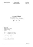
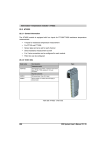
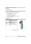
1
X20 module • Compact CPUs • CP0201, CP0291, CP0292
5.2 CP0201, CP0291, CP0292
5.2.1 General information
The Compact CPUs are ideal for situations where cycle times in the millisecond range are
acceptable and value is the deciding factor. A range of models with CAN and Ethernet can adapt
optimally to all demands. The result: extremely sleek automation solutions.
•
Embedded µP 16/µP 25 with additional I/O processor
•
100 KB / 750 KB User SRAM
•
1 MB / 3 MB User FlashPROM
•
CP0291 and CP0292: Ethernet on-board
•
Only 37.5 mm wide
•
Battery-free
Chapter 4
X20 module
5.2.2 Order data
CP0201
CP0291, CP0292
Model number
Short description
X20CP0201
X20 CPU, Compact CPU µP 16, 100 KB SRAM, 1 MB Flash FPROM, RS232 and CAN, corresponds
to Compact CPU base
X20CP0291
X20 CPU, Compact CPU µP 16, 100 KB SRAM, 1 MB Flash FPROM, RS232 and CAN support,
corresponds to Compact CPU base, 1 Ethernet interface 100 Base-T
X20CP0292
X20 CPU, Compact CPU µP 25, 750 KB SRAM, 3 MB Flash FPROM, RS232 and CAN support,
corresponds to Compact CPU base, 1 Ethernet interface 100 Base-T
Table 55: X20 Compact CPUs - Order data
X20 System User's Manual V 2.10
203
X20 module • Compact CPUs • CP0201, CP0291, CP0292
Model number
Required accessories
X20TB12
X20 terminal block, 12-pin, 24 V coded
X20BB22
X20 Compact CPU base, for Compact CPU and Compact CPU supply module, base for integrated
RS232 interface, X20 connection, X20 end plates (left and right), X20AC0SL1/X20AC0SR1 included
X20BB27
X20 Compact CPU base, for Compact CPU and Compact CPU supply module, base for integrated
RS232 and CAN interfaces, X20 connection, X20 end plates (left and right), X20AC0SL1/X20AC0SR1
included
X20PS9500
X20 supply module for Compact and fieldbus CPUs and internal I/O supply, X2X Link bus supply
X20PS9502
X20 supply module for Compact and fieldbus CPUs and internal I/O supply, X2X Link bus supply,
supply feed not electrically isolated
X20AC0SL1
X20 locking plate (left)
X20AC0SR1
X20 locking plate (right)
Included in delivery
Table 55: X20 Compact CPUs - Order data
5.2.3 Technical data
Product ID
CP0201
CP0291
CP0292
Short description
System module
CPU
Processor
Interfaces
Embedded µP 16
Embedded µP 25
-
1x Ethernet onboard
Controller
Fastest task class cycle time
4 ms
2 ms
Typical instruction cycle time
0.8 µs
0.5 µs
100 KB SRAM 1)
1 MB FlashPROM
750 KB SRAM 1)
3 MB FlashPROM
Standard memory
User RAM
User PROM
Permanent variables
Memory
Buffer duration
2.75 KB FRAM 2)
45 years
Backup battery
No
Integrated I/O processor
Processes I/O data points in the background
Real-time clock 3)
Yes, resolution 1 s
Interfaces
Interface IF2
Type
Design
Transfer rate
Cable length
Additional interfaces
X20BB22
X20BB27
Ethernet
Shielded RJ45 port
100 MBit/s
Max. 100 m between two stations (segment length)
Compact CPU base module with integrated RS232 interface
Compact CPU base module with integrated RS232 and CAN interfaces
Table 56: X20 Compact CPUs - Technical data
204
X20 System User's Manual V 2.10
X20 module • Compact CPUs • CP0201, CP0291, CP0292
Product ID
CP0201
CP0291
CP0292
General information
Status indicators
CPU function
Diagnostics
CPU function
Ethernet
Over-temperature
CPU function, Ethernet
Yes, with status LED
-
Yes, with status LED
Yes, with status LED
-
Yes, with status LED
Yes, with status LED
Yes, with software status
Visual Components capability
Limited (User PROM)
Yes
ACOPOS capability
Limited (User PROM)
Yes
Temperature sensor
No
Yes
Electrical isolation
PLC - IF2
-
Power consumption
Yes
2.2 W
Certification
2.7 W
3.0 W
CE, C-UL-US, GOST-R
Operating conditions
Operating temperature
Horizontal installation
Vertical installation
0°C to +55°C
0°C to +50°C
Relative humidity
5 to 95%, non-condensing
Mounting orientation
Horizontal or vertical
Installation at altitudes above sea level
0 - 2000 m
>2000 m
Protection type
No derating
Reduction of ambient temperature by 0.5°C per 100 m
IP20
Temperature
Chapter 4
X20 module
Storage and transport conditions
-25°C to +70°C
Relative humidity
5 to 95%, non-condensing
Mechanical characteristics
Spacing 4)
37.5 +0.2 mm
Comment
Order terminal block 1x X20TB12 separately
Order supply module 1x X20PS9500 or X20PS9502 separately
Order Compact CPU base 1x X20BB22 or X20BB27 separately
Table 56: X20 Compact CPUs - Technical data (cont.)
1) Not buffered.
2) This FRAM stores its contents ferroelectric alloy. Therefore, no buffer battery is needed.
3) The real-time clock is buffered for approx. 1000 hours by a gold foil capacitor. The gold foil capacitor is completely loaded after 18
continuous hours of operation.
4) Spacing is based on the width of the Compact CPU base X20BB22 or X20BB27. An X20PS9500 or X20PS9502 supply module is also
always required for the CPU.
X20 System User's Manual V 2.10
205
X20 module • Compact CPUs • CP0201, CP0291, CP0292
5.2.4 Status LEDs
CP0201
CP0291, CP0292
LED
Color
Status
Description
R/E
Green
On
Application running
Red
On
SERVICE mode
RDY
Yellow
On
SERVICE or BOOT mode
L/A
Green
On
A link to the Ethernet remote station has been established.
Blinking
A link to the Ethernet remote station has been established. The LED blinks when
Ethernet activity is present on the bus.
Table 57: X20 Compact CPUs - CPU status indicator
206
X20 System User's Manual V 2.10
X20 module • Compact CPUs • CP0201, CP0291, CP0292
5.2.5 Operating and connection elements
CP0201
LED status indicators
Node number switches
IF1 - RS232
IF3 - CAN bus (with BB27)
Terminal block for CPU
and I/O supply
RS232 connection
CAN bus connection (with BB27)
Switch for CAN bus terminating
resistor on BB27
Figure 82: X20 Compact CPUs - Operating elements for CP0201
Chapter 4
X20 module
CP0291 and CP0292
LED status indicators
Node number switches
IF1 - RS232
IF3 - CAN bus (with BB27)
IF2 - Ethernet
Terminal block for CPU
and I/O supply
RS232 connection
CAN bus connection (with BB27)
Switch for CAN bus terminating
resistor on BB27
Figure 83: X20 Compact CPUs - Operating elements for CP0291 and CP0292
X20 System User's Manual V 2.10
207
X20 module • Compact CPUs • CP0201, CP0291, CP0292
5.2.6 Node number switches
Figure 84: X20 Compact CPUs - Node number switches
The node number is set with the two hex switches. The switch setting can be evaluated by the
application program at any time. The operating system only interprets the switch position when
switched on.
Switch position
Operating mode
$00
Boot
In this switch position, the operating system can be installed via the RS232 interface configured as
online interface. User Flash is only deleted after the update begins.
Description
$01 - $FE
Run
RUN mode, the application is running.
$FF
Diagnostics
The CPU boots in diagnostics mode. Program sections in User RAM and User FlashPROM are not
initialized. After diagnostics mode, the CPU always boots with a cold restart.
Table 58: X20 Compact CPUs - Operating modes
CP0201
Together with the bus module BB27, the CP0201 has a CAN bus interface. The INA2000 station
number for CAN is set using the node number switches.
CP0291 and CP0292
These two CPUs are equipped with an onboard Ethernet interface. When the BB27 bus module
is used, they also have a CAN bus interface.
The number set with the two hex switches defines the INA2000 station number of both the CAN
an the Ethernet interfaces.
208
X20 System User's Manual V 2.10
X20 module • Compact CPUs • CP0201, CP0291, CP0292
5.2.7 Ethernet interface (IF2)
Figure 85: X20 Compact CPUs - Ethernet interface for CP0291 and CP0292
The CP0291 and CP0292 are equipped with an Ethernet interface. The connection is made
using a 100 BASE-T Twisted Pair RJ45 socket.
Please note the following section: 9.1.2 "Wiring guidelines for X20 bus controller with Ethernet
cable" on page 265
Information:
The Ethernet interface (IF2) is not suitable for POWERLINK.
Pin assignments
Assignment
1
RxD
Receive data
2
RxD\
Receive data\
3
TxD
Transmit data
4
Termination
5
Termination
6
TxD\
7
Termination
8
Termination
Chapter 4
X20 module
Pin
Transmit data\
Table 59: X20 Compact CPUs - Pin assignments - Ethernet interface (IF2)
X20 System User's Manual V 2.10
209
X20 module • Compact CPUs • CP0201, CP0291, CP0292
5.2.8 Programming the system flash
General information
CPUs are delivered with a runtime system. The node number switch is set to switch position $00
when delivered i.e. bootstrap loader mode is set.
A switch position must be set in order to boot the PLC in RUN mode ($01 to $FE). A runtime
system update is only possible in RUN mode.
Runtime system update
The runtime system can be updated using the programming system. When updating the runtime
system (online runtime system update), the following procedure must be carried out:
1) An online runtime system update is only possible if the processor is in RUN mode. To do this,
the set node number must be in the range from $01 to $FE.
2) Switch on the power.
3) The runtime system update is performed via the existing online connection. The online
connection can e. g. be established via the serial RS232 OnBoard interface. The update for
the Compact CPUs CP0291 and CP0292 can also be performed via the Ethernet interface.
4) Start B&R Automation Studio.
5) Start the update procedure by calling the Services command from the Project menu. Select
Transfer Operating System... from the menu shown. Now follow the instructions from B&R
Automation Studio.
6) A dialog box is displayed for configuring the runtime system version. The runtime system
version is already pre-selected by the user's project settings. Using the drop-down menu, the
runtime system versions stored in the project can be selected. Clicking on the Browse button
allows the selected runtime system version to be loaded from the hard drive or from the CD.
Pressing Next > opens a pop-up window, which allows the user to select whether the
modules should also be downloaded with SYSTEM ROM as the target memory during the
following runtime system update. Otherwise, modules can also be downloaded later with an
application download.
After pressing Next >, a dialog box appears where the user can set the CAN transfer rate,
CAN ID and the CAN node number (the CAN node number set here is only relevant if an
interface module does not have a CAN node number switch). The CAN node number must
be between decimal 01 and 99. Assigning a unique node number is especially important with
online communication over a CAN network (INA2000 protocol).
7) The update procedure is started by pressing Next >. The update progress is shown in a
message box.
210
X20 System User's Manual V 2.10
X20 module • Compact CPUs • CP0201, CP0291, CP0292
Information:
User flash is cleared.
8) When the update procedure is complete, the online connection is automatically
reestablished.
9) The PLC is now ready for use.
Chapter 4
X20 module
A runtime system update is not only possible through an online connection, but also through a
CAN network, serial network (INA2000 protocol) or an ETHERNET network, depending on the
system configuration.
X20 System User's Manual V 2.10
211