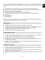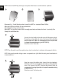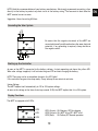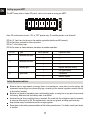
1
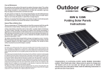
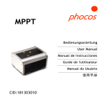
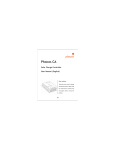
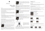
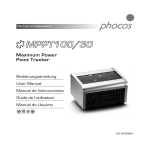
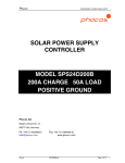
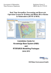
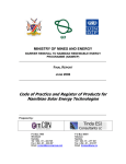
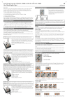
EN
The Core of Independence
MPPT100/30
Maximum Power Point
Tracker User Manual
(English)
The Core of Independence
Dear Customer,
Thank you very much for buying
this Phocos product. Please read
the instructions carefully and
thoroughly before using the
product.
EN
Contents
Major Functions
8
Recommendations for Use
8
Mounting and Connecting
8
Grounding the Solar System
10
Starting up the Controller
10
Display Functions
10
Setting up your MPPT
11
Safety Recommendations
11
Liability Exclusion
12
Technical Data
12
7
With your new MPPT Maximum Power Point Tracker, you own a state-of-the art device which was developed
according to the latest available technical standards. It comes with a number of outstanding features,
such as:
Maximum Power Point Tracking technology, which increases the efficiency of your PV system
Allows the use of less expensive solar panels for grid connection systems for 12/24V stand-alone systems
Automatically detects 12/24V system Voltage
Temperature-Compensated, Three-Stage I-U Curve Charge Regulation
Full electronic protection (Reverse Polarity, Over-Current, Short-circuit, Over-Temperature, etc.)
High efficiency
DIN rail compatible
Negative ground
This manual gives important recommendations for installing and using the MPPT. Read it carefully and mind
the safety and usage recommendations at the end of this manual.
Major Functions
The MPPT charges your battery much faster than a regular charge controller.
The MPPT protects the battery from being overcharged by the solar array. The charging characteristics
include several stages which include automatic adaptation to the ambient temperature.
The MPPT adjusts itself automatically to 12V or 24V system voltage.
The MPPT has a number of safety and display functions.
Recommendations for Use
The MPPT warms up during normal operation. if there is insufficient ventilation (e.g. in an installstion
cabinet), the controller limits the solar charge current to prevent overheating.
The MPPT does not need any maintenance or service. Remove dust with a dry tissue.
It is important that the battery is fully charged frequently (at least monthly). Otherwise the battery
will be permanently damaged.
A battery can only be fully charged if not too much energy is drawn during charging. Keep this in mind,
especially if you install additional loads.
Mounting and Connecting
The MPPT is intended for indoor use only. Protect it from direct sunlight and place it in a dry environment.
Never install it in humid rooms (like bathrooms).
The MPPT measures the ambient temperature to determine the charging voltage. The MPPT and the
battery must be installed in the same room.
The MPPT warms up during operation, and should therefore be installed on a non-flammable surface
only.
8
EN
EN
NOTE: Connect the MPPT by following the steps described below to avoid installation problems.
1
2
3
Please see Fig 1, 2 and 3 that show how to install the MPPT on a standard 35mm DIN Rail.
Make sure that the ventilation slits are unobstructed.
Mount Din Rail onto the vertical surface.
Mount MPPT in a way that ensures there is enough space below and above for the air to vertically flow
through the ventilation slots.
4
Connect the wires leading to the solar array with the proper polarity.
To avoid any voltage from the wires, first connect the controller,
then the solar array. Mind the recommended wire size (see table
in chapter Recommended wiring for MPPT100/30) .
Close the cover of solar side.
NOTE: Place the positive and the negative wires close to each other to minimize electromagnetic effects.
NOTE: Solar panels provide voltage as soon as exposed to sun light. Mind the solar panel manufacturer’s
recommendations.
5
Open the cover at the battery side. Connect the wires leading to
the battery with the correct polarity. To avoid any voltage from the
wires, first connect the MPPT and then the battery. Mind the
recommended wire length (see table in chapter Recommended wiring
for MPPT100/30) .
Close the cover of the battery side.
9
NOTE: Mind the recommendations of your battery manufacturer. We strongly recommend connecting a fuse
directly to the battery to protect any short circuit in the battery wiring. The fuse must at least take the
MPPT nominal current or more.
Suggestion: Use a slow acting 40A fuse.
Grounding the Solar System
Be aware that the negative terminals of the MPPT are
connected internally and therefore have the same electrical
potential. If any grounding is required, always do this on
the negative wires.
12345678
Address Mode
Starting up the Controller
As soon as the MPPT is connected to the battery voltage, it starts operating and shows the yellow LED.
When solar voltage is applied, it will activate the green LED and start charging the battery.
NOTE: There may not be an immediate change in the LED lights !
If the controller has gone into sleep mode, it may take up to one minute to activate.
System Voltage
The MPPT adjusts itself automatically to 12V or 24V system voltage.
As soon as the voltage at the time of start-up exceeds 18.0V, the MPPT implies that it is a 24V system.
Display Functions
The MPPT is equipped with 3 LEDs.
LED2
LED1
LED3
LED1 (Green): ON-Charging; OFF-No charging
LED2 (Yellow): ON- MPPT is on;OFF- MPPT is off
LED3 (Red):
ON-Failure;OFF-Normal operation
12345678
Address Mode
10
EN
EN
Setting up your MPPT
The MPPT comes with an 8 pole DIP-switch, which can be used to set up your MPPT.
SAB
+
ON
OFF
1
2
3
4
5
6
7
-
8
Note: DIP switches have to be in "ON" or "OFF" position only. The middle position is not allowed!!
DIP No.1,2,3 and 4 are for the use in the modular system(for details see MCU manual).
DIP No.5 and 6 are reserved for future functions.
DIP No. 7 is for battery type.
DIP No.8 is meant to choose between standalone or modular operation.
DIP NO.
Type
5
Reserved functions
6
7
8
Reserved functions
Battery type
Application
Switch position
Operation mode
-
---
+
---
-
---
+
---
-
Regular lead acid battery
+
GEL-type battery
-
Standalone
+
Modular system
Safety Recommendations
Batteries store a large amount of energy. Under no circumstances, never short-circuit a battery. We
recommend connecting a fuse (slow acting type, according to the nominal regulator current) directly
to the battery terminal.
Batteries can produce flammable gases. Avoid making sparks, or using fire or any open flame around
the battery. Make sure that the battery room is ventilated.
Avoid touching or short circuiting wires or terminals. Be aware that the voltages on specific terminals
or wires can be as much as 95V. Use isolated tools, stand on dry ground, and keep your hands dry.
Keep children away from batteries and the charge regulator.
Please observe the safety recommendations of the battery manufacturer. If in doubt, consult your dealer
or installer.
11
Liability Exclusion
EN
]The manufacturer shall not be liable for damages, especially on the battery, caused by use other than as
intended or as mentioned in this manual, or if the recommendations of the battery manufacturer are
neglected. The manufacturer shall not be liable if there has been service or repair carried out by any
unauthorized person, unusual use, incorrect installation, or poor system design.
Opening the case voids the warranty.
Technical Data
Type
Nominal Voltage
Nominal Battery Charge Current
Max. Solar Input Voltage Voc
Max. PV Input Power
Max. Battery Charge Current
Power Conversion Efficiency
Standby Power Consumption
Temperature Compensation
Max. Wire Size
Dimensions
Weight
Ambient Temperature range
Case Protection
MPPT100/30
12 / 24 V, Automatic Recognition
30 A
95 V
450 W@12 V, 900 W@24 V
33 A
Max. 98%
< 30 mW @12 V system voltage(< 2 mA)
< 80 mW @24 V system voltage(< 3 mA)
-4 mV/cell*K
32 mm2
185 x 150 x 115 mm
1.6 kg
-40 to + 50 °C
IP 22
Subject to change without notice.
ISO9001:2000
Version: 20090909
Made in one of the following countries:
China – Germany
RoHS
Phocos AG – Germany
www.phocos.com
12