1
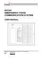
EVC40
EMERGENCY VOICE
COMMUNICATION SYSTEM
USER MANUAL
Protec Fire Detection PLC, Protec House, Churchill Way, Nelson, Lancashire, BB9 6RT.
Telephone:
+44 (0) 1282 717171
Fax:
+44 (0) 1282 717273
Web:
www.protec.co.uk
Email:
[email protected]
Document Revision Details
Issue
0
1
3
4
Modification Detail
Document Creation
General Update
Added detail in Conference Call and Listen In
New features added
93-345-79 Issue 4
2
Author
jlh
jlh
jlh
jg
Date
06/12/06
04/06/09
21/09/09
14/02/11
© Copyright Protec Fire Detection PLC 2011
Table of Contents
1.0
OVERVIEW ........................................................................................................................................................ 4
1.1 MAIN CONTROL UNIT (MCU) ............................................................................................................ 5
1.2 OPERATING THE EVC ........................................................................................................................ 6
2.0
DISABLED TOILET ALARM .......................................................................................................................... 9
3.0
FIRE INPUT ...................................................................................................................................................... 10
4.0
REMOTE CALL INDICATION ..................................................................................................................... 11
5.0
CALL FEATURES ........................................................................................................................................... 12
5.1 ALL CALL ........................................................................................................................................ 12
5.2 GROUP CALL.................................................................................................................................... 12
5.3 CONFERENCE CALL.......................................................................................................................... 13
5.4 LISTEN IN ......................................................................................................................................... 13
5.5 ON HOLD .......................................................................................................................................... 14
93-345-79 Issue 4
3
© Copyright Protec Fire Detection PLC 2011
1.0
Overview
The system is capable of driving up to 40 outstations per panel
4 panels can be networked together to give a total of 160 outstations.
Panels are the Master Control Unit (MCU), Repeat Control Units (RCU) or Audio Loop Processors
(ALPs).
MCUs and RCUs have a functional front panel whereas ALPs do not.
Outstations are mapped to the MCU or RCU using the commissioning software.
Definitions
Sounds
Dial Tone
Ringing Tone
Ring Tone
– Continuous Tone heard in Handset
– Intermittent Tone heard in Handset
– Intermittent Tone heard from unit Speaker
Panels
MCU – Master Control Unit
RCU – Repeat Control Units
ALP – Audio LoopProcessors
EVC Panel
ALP Panel
RCU Panel
PCB’s – MCU,
TERMINAL BOARD –
PDP – LCD – HANDSET
CHARGER – NETWORK
CARD IF NETWORKED
SYSTEM
PCB’S – MCU –
DISPLAY BOARD –
TERMINAL BOARD –
CHARGER – NETWORK
CARD
PCB’s – MCU,
TERMINAL BOARD –
PDP – LCD – HANDSET
CHARGER – NETWORK
CARD
Outstation Loops can
have up to 40 devices
connected per loop,
these can either
disabled refuge
points,
Disabled toilet alarms
or fire telephones or a
mix of all three
Disabled
Refuge Point
93-345-79 Issue 4
Disabled
Toilet Alarm
Fire
Telephone
4
© Copyright Protec Fire Detection PLC 2011
1.1 Main Control Unit (MCU)
(Repeat Control Units, RCUs, are similar units)
At the MCU, the operation is almost identical for both Fire Telephone and Disabled Refuge systems.
The front panel of the MCU is given below; this shows all the switches and indicators on the MCU.
40x8 Alphanumeric
LCD Display
PROTEC FIRE DETECTION PLC
06 DEC
14:12
System
Status
Indicators
Outstation call
buttons and
indicators
Handset
Control &
Mode
Selection
Switches
Descriptive Text
Windows
Numeric
Key Pad
Outstation Call Buttons and Indicators
A bank of 40 switches and indicators that allow calls to be connected to Outstations and Repeat Control
Units. The indicator above the switch shows the status of a call.
Descriptive Text Windows
The description & location text for the Outstations can be printed and inserted through a slot at the back
of the door.
LCD
This displays Time/Date & Status information and is used for advanced user functions. See Section 4
System Status Indicators
LEDs showing the system status. See section 5
Handset
Telephone handset used for all communications.
Control and Mode Selection Switches
Buttons used for mode selection and basic functions.
Numeric Keypad
Used for code entry and advanced user functions in conjunction with the LCD.
93-345-79 Issue 4
5
© Copyright Protec Fire Detection PLC 2011
1.2 Operating the EVC
Dial Tone
Ringing Tone
Ring Tone
– Continuous Tone heard in Handset
– Intermittent Tone heard in Handset
– Intermittent Tone heard from unit speaker
Picking Up a Call from an Outstation
Incoming Calls are indicated on the LCD, a flashing Red Led against the associated PDP button and the
Ring Tone (if a call is not already connected).
CALL
CALL
WAITING
CALLING: REFUGE POINT XX
LOCATION: SITE RELATED TEXT
1 CALL
TIME: TIME / DATE
ENTER/FN: SCROLL
For a single call:
Pick up the MCU handset to connect to the Outstation.
The Ring Tone will cease, the Outstation Indicator LED will go steady and the LCD will change to call
connected.
For Multiple Calls:
Pick up the MCU handset (the Ringing Tone will be heard in the earpiece).
Select the Outstation to answer by pressing the relevant button.
Flashing red indicators show other calls are waiting. Waiting calls do not produce the Ring Tone whilst a
call is connected.
93-345-79 Issue 4
6
© Copyright Protec Fire Detection PLC 2011
Making a Call to an Outstation
Pick up the handset, the Dial Tone can be heard.
Select the Outstation to be called by pressing the relevant button.
CALL
CALLING
WAITING: REFUGE POINT XX
LOCATION: SITE RELATED TEXT
1 CALL
TIME: TIME / DATE
ENTER/FN: SCROLL
The LCD will change to Calling, the ringing Tone can be heard and selected LED will flash Red.
Connection is established when the Outstation handset is picked up or the Call / Answer button is
pressed.
The Outstation Indicator LED will go steady.
Terminating a Call
Calls are terminated by replacing the handset at the MCU.
If the handset at a Fire Telephone outstation has not been replaced, the Outstation indicator LED will
continue to flash, and can be reconnected by pressing the relevant Outstation button.
NOTE – Factory Default software settings has buttons 33 – 36 allocated as panel
handsets. Therefore button 33 is allocated as handset on panel 1 and flashes
when the handset is lifted or called. As will 34 – 36 on their respective panels.
93-345-79 Issue 4
7
© Copyright Protec Fire Detection PLC 2011
1.3 Outstation Operation
Instigating a Call
Call are instigated by
a) Picking up the handset on a Fire Telephone Unit
b) Pressing the Call / Answer button on a Refuge Unit
Picking Up a Call at an Outstation
Incoming Calls are indicated by a) The Ring Tone on a Fire Telephone Unit
b) Flashing Red Led and the Ring Tone on a Refuge Unit
c) If a strobe is fitted for use on Fire Telephone or Disable Toilet Alarm
this will flash
The call is connected by
a) Picking up the handset
b) Pressing the Call / Answer button
Terminating a Call
Calls are terminated by
LED Colour
Green
Flashing Red
Steady Red
Steady Orange
93-345-79 Issue 4
-
a) Replacing the handset on a Fire Telephone Unit
b) The MCU controller replacing their handset
Outstation Healthy
Call waiting
Call acknowledge
Fault
8
© Copyright Protec Fire Detection PLC 2011
2.0
Disabled Toilet Alarm
Disabled Toilet Alarms are used in-conjunction with the outstations; the toilet alarm does not have a
specific address location. Separate Text from the Outstation text can be allocated during
commission. Once activated via the pull cord the toilet alarm will be displayed on the main panel
and will either display the address of the outstation that the toilet alarm is connected to, or the
location text. A fast bleep will be the audio indication of the toilet alarm being activated, this can be
muted at the panel by pressing ‘Mute’.
ALARM
DISABLED
TOILET
ALARM: DISABLED TOILET
ALARM
LOCATION: SITE RELATED TEXT
1 ALARM
TIME: TIME / DATE
ENTER/FN: SCROLL
93-345-79 Issue 4
9
© Copyright Protec Fire Detection PLC 2011
3.0
Fire Input
The Fire Input signal allows the fire alarm system to control the operation of the EVC panel.
By connecting a normally closed contact from the fire alarm system to the fire input on the EVC panel all
outstations will be disabled until the fire alarm is activated. Only calls from the EVC panel to the
Outstations is in operation while the system is disabled. System Disabled will be displayed on the LCD
screen while the Fire Input is closed.
Once the fire input is open all outstations will be able to send and receive calls to and from the EVC
panel.
If the user requires continuous operation from the outstations then no connection to the fire input is
required.
PROTEC FIRE DETECTION PLC
SYSTEM
DISABLED
22 MAY
09:29
Disabled Toilet Alarms will still function while the system is disabled.
93-345-79 Issue 4
10
© Copyright Protec Fire Detection PLC 2011
4.0
Remote Call Indication
The EVC panel has the function to drive a remote call indicator such as a RAIU, LED Beacon, Sounder
or even operate a relay by connecting the device to the terminal board. This allows the master panel to
be installed in a secure location while allowing calls to be monitored by end user. The call indicator will
operate when either an outstation or disabled toilet alarm is operated.
Connection of the remote indicator is as follows;
Terminal Board
93-345-79 Issue 4
11
© Copyright Protec Fire Detection PLC 2011
5.0
Call Features
5.1 All Call
There are two options available, Global All Call which actives all outstations on all panels, or Panel all
call. To enter this menu lift the handset on the control panel and press ‘All Call’, a menu will be
displayed upon the LCD. Select the option you require
PANEL 01 ALL CALL OPTIONS
0 EXIT MENU
1 GLOBAL ALL CALL
2 PANEL ALL CALL
Once option 1 is selected all outstation will be active and the green LED on the outstation will flash.
If option 2 is selected a further menu will appear to enable the required panel to be selected before the
outstations become active.
5.2 Group Call
Via the commissioning software, it is possible to group the outstations into groups 1 to 8 and assign
group text. Once done and the site file has been downloaded to the control panel, you can use this
option. To active group call lift the handset on the control panel and press Group Call. A menu option
will appear with groups 1 to 8. Select the require group and press enter to enable the call to the
required group.
CALL
GROUP
ALL CALL
ALL CALL: GROUP 2
GROUP: 2
LOCATION: SITE RELATED TEXT
1 CALL
TIME: TIME / DATE
ENTER/FN: SCROLL
93-345-79 Issue 4
12
© Copyright Protec Fire Detection PLC 2011
5.3 Conference Call
Conference call allows to-way communication between a control panel and up to four outstations. To
active conference call pick up the handset on the control panel press conference call and select the
outstations you require on the relevant call buttons. The call buttons will flash and the ring tone can be
heard. The LCD will show
CALL
CALL
1/2
PARTY
WAITING: GROUP 2
WAITING
LOCATION: SITE RELATED TEXT
2 CALLS
TIME: TIME / DATE
ENTER/FN: SCROLL
Once the outstations accept the call/s two-way communication will be established, between the
outstation/s and control panel. The LCD will change from waiting to In Call.
5.4 Listen In
The listen in feature allows you to select a outstation from the control panel and listen at the outstation
location. Further press of the outstation button will enable two-way communication. To active Listen
in, pick up the handset on the control panel press Listen In and select the outstation you require via the
call buttons. The call button will flash green, the outstation LED will flash green and the LCD will display
Listen In.
CALL
LISTEN - IN
LISTEN-IN: REFUGE POINT XX
LOCATION: SITE RELATED TEXT
1 CALL
TIME: TIME / DATE
ENTER/FN: SCROLL
Further pressing of the outstation call button will active two-way communication. The call button will
change to steady RED and the LCD will change to call connected.
93-345-79 Issue 4
13
© Copyright Protec Fire Detection PLC 2011
5.5 On hold
This feature allows you to place the present call connected on hold while allowing the user at the control
panel to select another incoming call. To use this feature press the On Hold button (on old overlays
labelled as Lock Release) which will place the connected call on hold, the call button on the control
panel will flash RED / GREEN. The LCD will change to indicate which outstation is on hold
CALL
CALL
WAITING
ON-HOLD: REFUGE POINT XX
LOCATION: SITE RELATED TEXT
1 CALL
TIME: TIME / DATE
ENTER/FN: SCROLL
To take the call off hold press the outstation call button, the call will be re-established.
93-345-79 Issue 4
14
© Copyright Protec Fire Detection PLC 2011