1
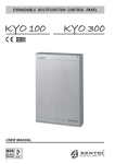
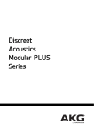
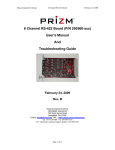
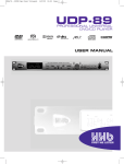
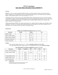
PDR1000TC ONLY
QUICK REFERENCE GUIDE
FEATURES & FUNCTIONS
9
PDR1000, PDR1000TC & PDR1000TC PLUS
10
FEATURES & FUNCTIONS
17
16
6
8
7
6
4
5
1
1
3
1
2
3
4
5
MS1000 MASTER SYNC
MODULE (optional) with
lemo connectors for timecode
I/O. Allows 30DF and NDF pull up.
2
13
source TIME CODE, displaying USER BITS and loading the
timecode from an external source to the internal generator
(LOAD TC (JAM)).
2
TIME CODE SOURCE selector sets timecode to be derived
either from the internal generator or from an external source
via the LTC IN socket.
6
TIME CODE MODE selector toggles the generator between free
run and record run.
8
FRAME RATE selector toggles timecode between 24, 25, 29.97
drop frame, 29.97 non-drop frame and 30 frames per second.
BACK-LIT DISPLAY showing timecode and user bits, frame
rate, sync mode, drop/non-drop frame indicator, timecode
errors, timecode lock and load timecode errors.
9
BNC CONNECTORS - output WORD SYNC, input VIDEO/
WORD SYNC and VIDEO/WORD SYNC THROUGH.
TIMECODE DISPLAY CONTROLS for switching from tape to
10 XLR sockets for linear timecode input and output.
•
The PDR1000TC records internal or external timecode, depending on the setting of the TIME CODE SOURCE switch. It also performs
timecode chase-sync playback and outputs timecode to other machines.
•
To set the internal generator, the PORTADAT should be in stop mode. Set the TIME CODE SOURCE to INT and press the TIME CODE key
until SOURCE TIME CODE appears in the display. Press SET and adjust the hours with the +/– keys. Pressing SET again moves the
flashing display along to the minutes section. After setting the frames, SET returns the display to normal - if the TIME CODE MODE is
set to free-run, counting starts immediately. REC RUN generates time code only when the PORTADAT is recording.
•
4
3
14
The LOAD TC (JAM) key forces the internal generator to display (and run) from an external source’s timecode value. For this to work
correctly, the PORTADAT’s frame rate must be set to match that of the external timecode source, and the timecode source selector
should be set to internal. This function is useful for recording audio linked to film or video with timecode.
12
11
9
7
TIMECODE GENERATOR CONTROL PANEL enables the user
bits to be set, reset, incremented or decremented. It is also
used to set the internal timecode generator.
8
7
USER BITS SOURCE selector toggles between external user
bits, manual use, date and external timecode.
SETTING THE TIMECODE
•
15
5
1
10
INPUT FORMAT SELECTION switches located
under the lid select either digital (AES/EBU or
SPDIF) or analogue inputs, and set the analogue
sampling rate. The cassette eject switch and
clock/calendar set functions are also located here.
2
INTERNAL MONITOR speaker.
3
ID KEYS for writing, erasing and renumbering
IDs. The START ID button changes ID writing
from auto to manual. END SEARCH positions the
cassette at the end of the recorded section.
DISPLAY CLOCK shows the clock/calendar and
level/margin information in the main display.
4
POWER switch; KEY HOLD slider which locks the
transport controls, and a slider for opening the
top lid (see 1 above).
5
TRANSPORT controls, allowing playback and
search of audio. ID SEARCH, REW/REV and
FF/CUE, PLAY and STOP keys.
8
HM1000 MS HEADPHONE MATRIX (optional).
9
REMOTE control port, parallel.
10 PHONES socket. 1/4" stereo jack.
11 MONITOR LEVEL control for headphones and
internal speaker.
12 BACK-LIT DISPLAY showing clock and counter,
battery level, metering, margin, source/tape
monitor, transport status and audio sample rate.
13 DISPLAY key selects: A-TIME (absolute time
from tape start), P-TIME (program time from
track start), COUNTER (time from pressing
RESET) and REMAIN (time remaining on the
tape). Display LIGHT, and TAPE/SOURCE
monitoring keys are also located here.
14 RECORD LEVEL CONTROLS, independent for left
and right channels; ID WRITE key.
To select the timecode output between tape or source, hold down TIME CODE and then select tape or source timecode with the +/- keys.
6
7
MIC/LINE switches, with high-pass filters for the
MIC inputs. Includes a +48V phantom power
switch, a 30dB microphone signal attenuator and
a mic LIMITER switch.
15 RECORD and PAUSE keys.
12V DC power input.
17 XLR sockets for AES/EBU digital I/O and
balanced analogue mic/line inputs.
HHB Communications Ltd · 73-75 Scrubs Lane, London NW10 6QU, UK
Tel: 0181 962 5000 · Fax: 0181 962 5050 · E-Mail: [email protected]
HHB Communications USA LLC · 626 Santa Monica Boulevard, Suite 110, Santa Monica, California 90401, USA
Tel: 310 319 1111 · Fax: 310 319 1311 · E-Mail: [email protected]
HHB Communications Canada Ltd · 260 King Street East, Toronto, Ontario M5A 4L5, Canada
Tel: 416 867 9000 · Fax: 416 867 1080 · E-mail: [email protected]
Visit HHB on-line at: http://www.hhb.co.uk
PORTADAT PDR1000TC PLUS
16 PHONO sockets for SPDIF digital I/O and
analogue out L/R.
consists of the timecode PORTADAT with the
HM1000 Headphone Matrix and MS1000 Master Sync module fitted as standard.
HOW TO PLAY BACK
Recording Basics
1
Insert a cassette and press PLAY. The green LED will light.
•
Insert a fully charged nickel metal hydride battery into the compartment at the rear of the PORTADAT.
Alternatively, connect a 12V power supply to the PORTADAT’s power input. Switch the power on.
2
The PORTADAT features a standard cassette-style transport, with rewind and forward wind keys for cueing
any audio whilst in playback mode.
•
For a new tape, insert the cassette with its label uppermost and press REWIND to spool the tape to the
start. Set up the PORTADAT for the input type, as described in the sections below, to start the recording.
3
The ID SEARCH keys skip to the previous/next ID start point during playback. With the pause key pressed,
the PORTADAT skips to the required ID but playback remains paused.
•
To find the end of a partially recorded cassette, insert the cassette and press END SEARCH, or FF/CUE if
currently in a recorded section.
•
For recording part way through a pre-recorded cassette, insert the cassette and spool to the desired
position, using audio output or time display as a guide.
ENTERING SUBCODE INFORMATION
NOTE: To write or erase any ID during replay, the DAT cassette must be record enabled.
Recording from an Analogue Input
1
Lift the top flap of the PORTADAT and set the switch inside to ANALOGUE input.
2
Select the sampling frequency (32kHz LP, 44.1kHz and 48kHz). In long play mode (the sampling frequency
switch is set to 32LP), the tape moves at half speed.
3
Connect the input audio signal to the balanced LINE/MIC L/R connectors on the side of the PORTADAT,
selecting the MIC or LINE input as appropriate.
4
The microphone inputs have optional high pass filters - these may be added by sliding the MIC/LINE
selector switch to the far right.
5
When using the microphone inputs, +48V phantom power may be added with the PHANTOM switch. The
LIMITER allows peak input signals to be limited, helping to avoid distortion in the recorded signal. There is
also an attenuation switch if the MIC signal is too high.
6
Press the TAPE/SOURCE key so that SOURCE appears in the display.
7
Adjust the recording level with the record level control (the outside controls the left channel, the inside
controls the right) so the peak level meters do not go over 0dB for the highest level input sound. The signal
will be digitally clipped if the input level is too high. Pressing DISPLAY CLOCK until MARGIN (dB) appears
in the display gives an indication of the recording headroom. This can be reset with the RESET key.
8
To use a microphone and a line input simultaneously, use the left input for one and the right input for the
other, setting the MIC/LINE switches as required.
9
Slide the red RECORD key to the right - recording begins immediately. To record from standby, press the
PAUSE key before moving the RECORD switch and then press PAUSE again to actually start recording.
Recording may be paused or stopped at any time, unless an ID is being written.
•
The PORTADAT is capable of recording absolute time, start and end IDs and program numbers into
subcode. It also records the time and date using information from its internal clock.
•
Subcode information has no effect on actual audio recorded on the tape.
•
IDs are a useful way of marking starts of tracks or takes. Whenever the PORTADAT is put into recording
mode, a start ID is written.
•
With the START ID switch in the manual position when recording, IDs are added by pressing the ID WRITE
key on the front panel. With the switch in the automatic position, IDs are added whenever there are three
seconds of silence. However, for recordings with periods of silence such as dialogue recording, the AUTO
ID setting can add unwanted START IDs. It's generally better to add them manually.
•
During playback, IDs can be added by pressing ID WRITE at the correct location. The PORTADAT then
auditions the ID point by repeatedly playing three seconds of tape from the point where the START ID key
was pressed. This point can be moved earlier or later using the rewind and cue keys. When you're
satisfied with the point’s position, pressing START ID again will set this point for the ID. The audio will be
muted for 9 seconds (18 in LP mode) while the ID is written - playback continues after this.
•
There should be at least eighteen seconds between each start ID for the skip ID function to work correctly.
•
To erase an ID, skip to the required ID and press ERASE ID. The PORTADAT will search backwards and
erase the first ID it finds.
•
End IDs are recorded with the END ID WRITE key. Once the end of the tape is found, press STOP, PAUSE,
then slide the record key to the right. Pressing END ID WRITE now will create an end ID point. These can
be removed at a later date by spooling the cassette to the end until it stops and then pressing ID ERASE.
•
With many IDs on one cassette being added or removed, it is useful to renumber them. Pressing
RENUMBER while the tape is stopped or during playback causes the tape to rewind back to the start, then
fast forward until the first ID is found. This will be numbered ‘1’, the next ‘2’ and so on to the end of the
tape. There is no audio output during renumbering.
Recording from a Digital Input
1
Lift the top flap of the PORTADAT and set the switch to DIGITAL input.
2
Connect the digital signal via either the AES/EBU inputs (for XLR connectors) or the SPDIF inputs (phono
connectors) and then choose the correct setting on the DIGITAL I/O switch for this input format.
3
Recording level controls and the limiter and mic/line switches are inactive when the input signal is from a
digital source.
PORTADAT OPTIONAL UPGRADES
MS1000 Master Sync Module
•
The optional master sync module’s accurate clock ensures that timecode drift is no more than 1 frame in
10 hours, allowing long term jam syncing via either the XLR or lemo connectors. If there are two input
timecodes, the lemo connector timecode will always take priority.
•
To pull the timecode generator up from 29.97 DF or NDF to 30 DF or NDF, slide the ON/OFF switch on the
side panel. The green LED will light and the display will show the sync mode as video.
MONITORING
•
Recordings are monitored through headphones or via the on-board loudspeaker. The levels of both are
adjusted via the recessed MONITOR LEVEL control on the front panel.
•
To monitor off tape during recording, press TAPE/SOURCE so that the TAPE indication appears. Note that
the output from PORTADAT’s read-after-write head will be slightly delayed from the signal being recorded.
The MONITOR LEVEL control will not affect the analogue and digital outputs.
HM1000 Headphone Matrix
•
The HM1000 acts as a MS decoder for monitoring purposes - a rotary switch selects headphone
monitoring for mono, stereo and MS signals. Settings do not affect signal going to tape in any way.
PORTADAT Portable DAT Recording System
HOW TO RECORD