1
COMPUTER SYSTEMS
ALTOS MAGNETIC TAPE UNIT SUBSYSTEM
USER'S MANUAL
October 1981
ALTOS COMPUTER SYSTEMS
236~
Bering Drive
San Jose, Californina 95131
ALTOS MAGNETIC TAPE UNIT SUBSYSTEM
USER'S MANUAL
October 1981
236~
Copyright (c) ALTOS Computer Systems
Bering Drive, San Jose, California 95131
NOTICE
ALTOS Computer systems makes no warranty of any kind with regard
to this material,
including, but not limited to, the implied
warranties of merchantability and fitness for a particular
purpose. ALTOS Computer systems assumes no responsibility for
any errors that may appear in this document.
ALTOS Computer
Systems makes no committment to update nor to keep current the
information contained in this document.
Tne information
contained in this document is subject to change without notice.
No part of this document may be copied or reproduced in any form,
or by any means, without prior written consent of ALTOS Computer
Systems.
Table of Contents
Section
Title
Page
1.
INTRODU~T ION •••••••••••••••••••••••••••••••••••••••
1.1
1.5
Tape Unit Hardware Features •••••••••••••••••••••••• l-l
Data Format on Tape •••••••••••••••••••••••••••••••• l-~
Error Recognition and Correction ••••••••••••••••••• 1-2
Maguetic Tape Cartridge Media •••••••••••••••••••••• 1-3
Tape Unit Software and Programming ••••••••••••••••• 1-4
2.
TAPE UNIT INSTALLATION AND CHECK-OUT ••••••••••••••• 2-1
2.1
2.",
Tape Unit Installation ••••••••••••••••••••••••••••• 2-1
Tape Un1t Cneck-out •••••••••••••••••••••••••••••••• 2-1
3.
TAPE UNIT OPERATION AND MAINTENANCE •••••••••••••••• 3-1
3.1
3.2
3.",.l.
3.2.2
3.~.",
Tape Cartridge Insertion and Removal ••••••••••••••• 3-1
Periodic Tape Unit Maintenance ••••••••••••••••••••• 3-1
Read/Write Head Cleaning ••••••••••••••••••••••••••• 3-l
Tape Cleaner Component Cleaning •••••••••••••••••••• 3-3
Motor Capstan Cleaning ••••••••••••••••••••••••••••• 3-3
4.
FILE BACK-UP AND RECOVERY •••••••••••••••••••••••••• 4-1
4 • .1
4.2
File Back-up and Recovery Requirements ••••••••••••• 4-1
Back-up/Recovery Capabilities •••••••••••••••••••••• 4-1
Tape Interchange Program (TIP) ••••••••••••••••••••• 4-1
File Back-up Utilizing TIP ••••••••••••••••••••••••• 4-2
TIP Fi.1e Name Conventions •••••••••••••••••••••••••• 4-3
Tape Interchange Program (TIP) Operation ••••••••••• 4-5
Invoking TIP and Entering TIP Commands ••••••••••••• 4-5
TIP Commands ••••••••••••••••••••••••••••••••••••••• 4-5
TIP File Name Parameters ••••••••••••••••••••••••••• 4-7
TIP Back-up and Restore Function Examples •••••••••• 4-9
TIP Tape Recording Procedure ••••••••••••••••••••••• 4-14
1.",
1.3
1.':1:
• .l.
4.2.2
4.~
4.", • .)
4.3
4.3.1
4.3.2
4.3.",
4.3.4
4.4
5.
1-1
ERROR CODES, TROUBLESHOOTING AND PROBLEM
DIAGNOSTICS •••••••••••••••••••••••••••••••••••••••• 5-1
5.1
5.",
5.3
5.4
5.5
5.::>.l.
5.5.2
5.::> • .:S
5.5.4
5.:>.:>
TIP Error Conditions ••••••••••••••••••••••••••••••• 5-1
File Specification Errors •••••••••••••••••••••••••• 5-1
Inadequate Disk Space DuringRestore •••••••••••••••• 5-1
'Full Tape Cartridge' Conditions ••••••••••••••••••• 5-1
Tape Media and Tape Unit Malfunctions •••••••••••••• 5-1
General Error Codes •••••••••••••••••••••••••••••••• 5-2
Sub-error Codes •••••••••••••••••••••••••••••••••••• 5-2
Error Analysis ••••••••••••••••••••••••••••••••••••• 5-4
Tape Unit Status Codes ••••••••••••••••••••••••••••• 5-4
Error Recovery Techniques •••••••••••••••••••••••••• 5-7
iii
Table of Contents (Continued)
section
Title
Page
6.
STAND-ALONE MAGNETIC TAPE CARTRIDGE BACK-UP UNIT
WITH ACS8000 COMPUTERS •••••••••••••••••••••••••••••• 6-1
6.1
6.1.1
8200 CPU PCB
Installation
8500 CPU and
Installation
6.~
6.2.1
and MTU-l ••••••••••••••••••••••••••••••• 6-1
of the MTU-l •••••••••••••••••••••••••••• 6-l
MTU2 •••••••••••••••••••••••••••••••••••• 6-6
of MTU-2 •••••••••••••••••••••••••••••••• 6-7
iv
List Of Figures
Figure
Page
Title
3-1
Tape Un1t Components Requ1ring C1eaning ••••••• 3-2
6-1
6-2
R~ar
6-3
8299 CPU PCB with Tape Controller PCB Mounted.6-2
Panel of ACS8899 Computer for Connection
to MTU-1 Chassis •••••••••••••••••••••••••••••• 6-4
8599 Central Processing Unit Printed C1rcuit
Board and MTU-2 Controller Board Mounted •••••• 6-8
v
ALTOS MAGNETIC TAPE UNIT SUBSYSTEM
USER'S MANUAL
1.
INTRODUCTION.
The ALTOS magnetic tape unit (MTU) subsystem provides
efficient back-up and restoration capabilities for program and
data files. The tape unit subsystem consists of a CMTD-3400S2
tape drive from Data Electronics, Inc. This drive comes as
either a stand alone unit which can be electrically connected
to the ACS8000 system by cables or, as an integral part of the
ACS8000 system itself. Provided with the MTU subsystem is a
copy of the Tape Interchange Program (TIP). TIP is a product
of Alloy Engineering Company, Inc. TIP provides all necessary
capabilities to back-up and restore both floppy disk and
hard disk files of any size under CP/M* and MP/M* only. with
TIP tne user has the capability of backing up and/or restoring
entire disk systems and individual program and data files.
This manual is divided into six sections. The
remainder of section 1 provides an overview of the tape unit
subsystem. Section 2 discusses installation and check-out
procedures of the tape unit subsystem. Section 3 provides
the operating procedures for the tape unit subsystem. Section
4 discusses the use of TIP. Section 5 discusses error
conditions and provides troubleshooting and diagnostic
instructions. Section 6 contains the procedure to incorporate
tne tape unit (MTU-l) with the ACS8000 computers.
1.1
Tape Unit Hardware Features.
The tape unit provides high density tape cartridge
storage of up to 13.4 MBytes of data on a single 1/4", 450-foot
magnetic tape cartridge, using four tracks. Data is written at 6400
bits/inch in Modified Frequency Modulation (MFM) format at a data
transfer rate of 192 Kbits/second. A serial recording format is
used.
Tne tape unit operates at two speeds depending on the
operation being performed:
a.
READ and WRITE operations are performed at a
tape speed of 30 inches/second.
b.
Bidirectional search and rewind operations are
performed at a tape speed of 90 inches/second.
*CP/M and MP/M are trademarks of Digital Research
1-1
1.1
--Continued.
The use of an integral DC motor tachometer that drives the
cartridge directly (no pulleys, belts or right angle friction
drives) allows the drive to sustain a start/stop time of 25-26
msec at a tape speed of 30 inches/second and 71-74 msec at
a tape speed of 90 inches/second.
All code conversions (NRZ/MFM and MFM/NRZ) are done
in the tape control unit thus reducing the amount of interaction required by the CPU of the ACS8000.
The tape unit contains several standard features
designed to improve system reliability:
1.2
a.
An integral tape cleaner which continually
cleans the tape while it is moving.
b.
The dual gap, read-while-write tape head insures
that all written data can be read back from the
tape.
c.
A separate erase head insures data reliability
of the tape unit to less than 1 error per
100 Mbits read by the drive.
Data Format on Tape.
The tape unit records data in serial fashion on
each of four tracks of the cartridge. When data is written
to the tape unit it is written first to track 1, and the tape
rewinds; data is written to track 2, and the tape rewinds;
data is written to track 3, and the tape rewinds; data is
written to track 4. There is an early warning indicator near
the end of each track. The sensing of that indicator will
cause tne tape to rewind.
The tape cartridge must be initialized before it
is used for the first time. The initialiation procedure is described in section 4.
1.3
Error Recognition and Correction.
Tne design of tne tape unit provides exceptional
reliability. The provision of reading all data immediately
after it is written is the key element to this reliability.
The tape head on the unit has both a READ and WRITE
head designed so that a~=~he data is written to the tape by the
WRITE head, it is immediately read by the trailing READ head.
If no errors are detected during this process the data has been
properly written to the tape.
1-2
1.3
--Continued.
If an error is detected by the trailing READ head
during a write operation, the tape unit attempts to re-write
the file as many as 16 times. Before each attempt the
unit rewinds the tape to the point at which tne file begins and
the unit will then advance the tape 3 inches and attempt to
write the file again erasing old file names. It will do this each
time an error is detected up to a maximum of 16 attempts. If,
at any time, the attempt is successful no further attempts will
be made. This forward movement of the tape 3 inches from the
beginning of the file each time an attempt is made ensures that
the portion of tape used for a file of 2500 bytes or less is bypassed.
If an error is detected during a read operation, the
tape unit will re-read the data block a maximum of 16 times
before signalling an aborted read operation. The incidence of
permanent read errors is very slight because of the movement of
the tape past the tape cleaner and read head 16 times. This action
removes many of the contaminants that cause permanent read
errors. If the 16 re-tries still result in a permanent read
error it is likely that the tape has physical damage or is
of poor quality and should be discarded.
The tape unit has another feature to increase
reliability. The built-in tape cleaner will remove contaminants
from the tape media prior to passing the read/write heads. The
tape unit generates a rewind of the tape each time the
cartridge is inserted into the unit and at the end of most
data operations. This procedure ensures that only the 36 inches
of tape between the beginning of tape indicator and the load
point at which data recording begins, is exposed to possible
contamination by smoke, finger prints, or other foreign matter.
1.4
~hat
Magnetic Tape Cartridge Media.
The tape unit subsystem utilizes 1/4 n tape cartridges
meet the ANSI X 3.55-1977 standard.
ALTOS recommends that all cartridges be certified at 6400 bpi
by the manufacturer: Scotch DC-300A, Scotch DC-300XL and Verbatim
TC-4450 tape cartridges are examples of acceptable media.
1-3
1.4
--Continued.
The tape unit has built-in sensors that identify
beginning of tape, end of tape, load point and early warning
location. The tape unit controller automatically recognizes
these sensor indicators and ensures that data is written 6
inches beyond the loading point and will continue no more
than 36 inches beyond the early warning location indicator.
In order to take advantage of these sensor indictors the
selected media cartridges should incorporate these features
as per the ANSI compatability specifications.
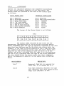
Tape cartridges of both 300 and 450 feet will be
accepted by the tape unit. The storage capacity of these
cartridges depends upon the length of the records being written.
The longer the records, the fewer the number of inter-record gaps
(IRGs) and, hence, the greater the efficiency of the unit.
Table 1-1 lists storage capacities of formatted tape cartridges
based on differing block lengths.
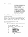
Table 1-1. Storage Capacities--Formatted Tape Cartridges
BLOCK SIZE
(BYTES)
125
1024
2048
4096
*8192
BLOCK LTH
(INCHES)
0.2
1.3
2.5
5.0
10.0
450' TAPE
300' TAPE
(RECORDS) (MBYTES) (RECORDS) 1MBY'!'t;:;)J
7000
5110
3349
1983
1092
3.5
5.3
6.8
8.1
8.9
10500
7664
5024
2975
1638
5.3
7.9
10.3
12.2
13.4
*the 8192- Bvte Block is used by TIP
Handling and storage of tape cartridges are
critical to the reliability and overall performance of the
tape unit subsystem. Excessive heat, humidity or exposure
to magnetic fields will cause substantial increases in the
rate of both temporary and permanent tape media errors. The
user is cautioned to follow the handling and storage
recommendations of the tape manfacturer to insure satisfactory
performance of the tape unit subsystem.
1.5
Tape Unit Software and programming.
The Tape Interchange Program (TIP), which comes
on either diskette or on cartridge, provides all the necessary
software to use the tape unit subsystem for back-up and recovery
of disk data and program files. TIP provides for automatic
back-up and recovery for entire disk units or individual files.
Automatic linkage of tape cartridges allows virtually unlimited
back-up storage capacity utilizing TIP.
1-4
2.
TAPE UNIT INSTALLATION AND CHECK-OUT.
2.1
Tape Unit Installation.
The Magnetic Tape Unit used with ACS8000 computer
systems comes as either a stand alone unit which is connected
electrically by ribbon cables to the host computer or as an
integral part of the computer system itself. Instructions to
install and connect the stand alone tape unit are sent with
the MTU when it is shipped to the user. There are no
installation procedures for tape units which are part of
the computer system itself.
2.2
Tape Unit Check-out.
To check out the tape unit prior to using it for
the first time you will need TIP. If your system has 1 or
more floppy disk drives and a hard disk you will need to
use your operating system disk and create a system which
will warm boot from the hard disk. Once this is done you
can log on to the hard disk, execute a mode command to
set drive A to single density, insert the TIP disk,
log on to drive A and enter TIP (carriage return). This
will provide you with a menu. Select the Initialization
program and the tape unit will write a data pattern to
all tracks of the tape. Each of the 4 tracks will have a
different pattern written to it. This ensures that two
tracks are not being written to at the same time. After
the write operation is complete a read operation will be
performed on each track to ensure the unit is writing
properly and reading properly. Once complete, file marks
are written to each of the four tracks. This completes
initialization.
Once initialization is successfully completed,
TIP should again be used to back-up sample files to all
tracks of the tape.
2-1 (2-2 Blank)
3.
TAPE UNIT OPERATION AND MAINTENANCE.
3.1
Tape Cartridge Insertion and Removal.
BE CERTAIN ~T NO TAPE CARTRIDGE IS IN ~E
TAPE UNIT WHEN THE TAPE UNIT, OR SYSTEM, IS
POWERED-ON OR POWERED-OFF. ~IS WILL PROTECT ~E
TAPE CARTRIDGE FROM DAMAGE CAUSED BY ~ICAL
TRANSIENTS.
The tape cartridge can only be inserted into the
tape unit in one way. A keylock prevents insertion of the
cartridge upside-down. Position the cartridge at the entry
opening of the tape unit and slide the cartridge forward
until the first detent is felt, then slide the cartridge
forward until it is fully engaged.
When the cartridge is inserted it will automatically be rewound and then advanced forward to the load
point. If the tape has been set to the "safe" pOSition (a
form of write protect) this will be sensed when the cartridge
is inserted into the tape unit. The control unit is informed
and the cartridge will have to be removed for only a write
operation.
There is no override for a write protected tape.
To remove the tape cartridge simply pull it from the unit.
NOTE: do not atteapt to reaove the tape cartridge while
any type of data transfer is underway.
3.2
Periodic Tape Unit Maintenance.
Three components of the tape unit require periodic
maintenance in order to insure overall system reliability. The
cleaning removes contaminants from the tape unit components
which come into direct contact with the tape media. Cleaning
insures that there will be adequate direct contact between
the read/write head of the tape unit and the tape itself.
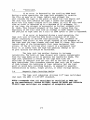
The location of the components which require
cleaning are shown in figure 3-1. The unit should be turned
off before any cleaning is done. The components to be cleaned
are accessed through the cartridge loading slot. A flashlight
should be used to better view the components.
3.2.1
Read/Write Head Cleaning.
The magnetic read/write head should be cleaned daily
if the tape unit is in regular use. Dirty heads may cause data
drop-outs and error conditions during read or write operations.
Use a non-residue, non-corrosive cleaning agent, such as
Dupont Freon TF or isopropyl alcohol, and a cotton swab to clean
the head assembly. Be sure to wipe off any excess and allow the
heads to dry completely before operating the unit.
3-1
CAPST
l .' .-
I
I
I
--- ~ --
I
I
(Area within dotted line is
Figure 3-1.
Tape Unit Components Requiring Cleaning
3-2
3.2.1
--Continued.
CAUTION: SPRAY TYPE HEAD CLEARERS ARE NOT RECOMMENDED.
AN OVERSPRAY MAY CONTAIIIlIATE "f'BE MOTOR BEARIRGS. NEVER
CLEAR THE HEAD WITH MY BARD OBJECT. THIS WILL RESULT
IN PERMANENT HEAD DAMAGE.
3.2.2
Tape Cleaner Component Cleaning.
The tape cleaner removes loose tape oxide and other
foreign material from the tape beore it contacts the head. This
foreign material accumulates in and around the tape cleaner
and must be removed to ensure that the tape cleaner will
continue to work effectively. The tape cleaner should be cleaned
on the same schedule as the head.
To clean the tape cleaner component insert a folded
sheet of paper in the bottom of the cleaning slot of the tape
cleaner and lift up. This will lift out the foreign material
gathered around the tape cleaner. Compressed air or an air
brush can also be used. During alternate cleaning periods
the same materials used to clean the heads can be used.
CAUTION: DO NOT USE MY BARD OBJECTS TO CLEAR THE TAPE CLEARER.
IF ~E TAPE CLEANER SHOULD BECOME CHIPPED, IT COULD SCRATCH "f1IE
TAPE SURFACE, RESULTIRG IB LOST DATA ABO/OR PERIIARENT DAMAGE.
3.2.3
Motor Capstan Cleaning.
The drive capstan is composed of hard polyurethane
and must be cleaned after foreign material has built up. Clean
the capstan using isopropyl alcohol and a cotton swab. The
cleaning schedule should be the same as for the other components
listed earlier.
CAUTION: BE VERY CAREFUL NOT TO PERliIT CLEARIRG
TO CONTAIIIRATE ~E DRIVE MOTOR BEARIRG.
3-3 (3-4 Blank)
SOLVE~
4.
FILE BACK-UP AND RECOVERY.
4.1
File Back-up and Recovery Requirements.
The ALTOS tape unit subsystem provides both the
hardware and software necessary to back-up and restore data and
program files of any size. The tape unit allows total back-up
of a formatted 14.5 MByte hard disk on one cartridge.
However, this system is only as reliable as the
back-up procedures employed. It is the responsibility of the
user to determine which capabilities of the back-up/recovery
system are required for the operation involved and then
implement those procedures to ensure that the required files
are backed-up at the required intervals.
The reliability of the back-up/recovery system
hinges on two factors:
a.
b.
The discipline with which key data files are
backed-up onto tape. The most functional
and reliable tape back-up system 1S of no
value, if, at the one time it is needed,
the required data and program files were
not backed-up in accordance with established
procedures.
The care with which the tape cartridge containing the backed-up files are handled. The weakest
link in the reliability chain is tape media
which has been stored in hot or humid conditions,
or has been placed near magnetic or electrical
fields.
4.2
Back-up/Recovery Capabilities.
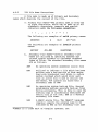
4.2.1
Tape Interchange Program (TIP).
The ALTOS file back-up and recovery system is
implemented through a program called the Tape Interchange
Program (TIP). TIP is distributed on diskette and/or tape
and comes as part of the MTU system. At present, TIP provides
seven functions that work together to provide complete file
back-up and recovery.
FUNCTION
TAPE INITIALIZATION
PURPOSE
writes two file marks at the start
of each of the four tracks of the
tape. Upon completion of this
function the tape can be utilized
for back-up and recovery operations
4-1
--continued.
4.2.1
FUNCTION
PURPOSE
DISK-TO-TAPE BACK-UP
Places a user-specified file or
files onto the tape from a user
specified disk
DISK-TO-TAPE RESTORE
Restores user specified data files
previously stored on tape onto a
user specified disk drive
DISK-TO-TAPE APPEND
Adds additional files to a tape
which already contains data or
program files.
FILE VERIFICATION
Compares a file which has been
backed-up to tape with a file
of the same name, stored on a disk
TAPE DIRECTORY
Lists the names of all data and
program files contained on the tape
RETENSION TAPE
Spools forward at 90 ips to end
of tape and then rewinds a tape
cartridge to ensure tape tension
meets manufacturers specifications.
This function will cure many error
conditions which occur during tape
use
4.2.2
File Back-up Utilizing TIP.
There are two general ways in which data and program
files are backed-up to tape.
a.
with the exception of a random write,file back-up
is utilized for those applications where either
an entire disk is to be backed-up or a family of
data and program files are to be backed-up.
b.
Individual file back-up is utilized where only
individual data or program files are to be
backed-up to tape.
TIP supports both types of back-up requirements
through the use of ambiguous and unambiguous file names. The
file naming system utilized by TIP is identical with CP/M*
and MP/M* file naming conventions.
4-2
4.2.3
TIP File Name Conventions.
A file name is made up of Primary and Secondary
names which describe the content of the file.
a. Primary File Names--The primary name is from one
to eight characters, which can be made up of all
alphabetic characters, numerals and special
characters with the following exceptions:
< >
•
, ., : =
?
*
[
]
The following are examples of valid primary names:
ABCDEFGH
A
Xl23
A@\-"22Z
The following are examples of invalid primary
names:
ABC?DEF
b.
JKL.MNO
PQRSTUVWX
Secondary File Names--several secondary file
names are utilized by operating systems and
related system software to represent standard
types of files. The standard secondary file names
are as follows:
ASM
An operating system assembler source file
BAD
Utilized to indicate a file which has been
written onto a bad portion of disk media.
Used with Winchester hard disks to reduce
system overhead which would occur each
time an active file tried to utilize the
bad media. TIP ignores all files with a
secondary name of BAD
BAK
An operating system back-up file. Several
programming systems generate back-up files
during processing. This is done in case the
working copy is accidentally destroyed the
entire file is not lost. BAK is a default
secondary file name.
BAS
A BASIC source file. The CBASIC* language
compiler expects the program name to be
followed by BAS as the secondary file name
*CBASIC is a trade mark of Compiler Systems, Inc.
4-3
4.2.3
--continued.
COM
An operating system command file. Programs
which can be loaded directly into the system
and executed are given the secondary file
name COM
INT
A BASIC language intermediate file.
Intermediate files are generated by
compilers such as CBASIC
SUB
An operating system command list file. Files
which contain lists of operating system
commands which may be executed by the user
through the use of SUBMIT commands are given
the secondary name of SUB
$$$
An operating system temporary file. System
programs which must generate temporary
files in the course of their execution
use the secondary file name of $$$
Although it is good programming practice to utilize
these operating system default secondary names it is
not mandatory to do so. If an installation determines
that other secondary names are more appropriate,
they may be used as well.
c. Unambiguous File Names--When valid Primary and
Secondary names are combined, they form an
unambiguous file name. Examples of valid
unambiguous file names are:
ABC.ASM
12345678.BAS
A.B
d. Group File Names--In many applications, the
ability to refer to families of files is useful.
For example, a diskette might contain program
files, data files and executable load module
files. You may wish to offload all program
files to a back-up tape. This would be much easier
if you could refer to all program files with a
single name. This is accomplished through the use
of Group File Names. In converting unambiguous
file names to group file names which represent
families of files, two special editing characters
are used:
4-4
4.2.3
--Continued.
?
Whenever the operating system finds a
question mark in a file name, it will
consider any character to be a match
*
The asterisk in either the primary or
secondary file name position tells the
operating system to consider any primary
or secondary name marked with * to be a
match.
The user's manual for your operating system gives
examples of files using the two special characters
described above.
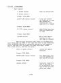
4.3
Tape Interchange Program (TIP) Operation.
4.3.1
Invoking TIP and Entering TIP Commands with a Diskette.
TIP is stored as a COM file and will execute under
both CP/M and MP/M operating systems. Once the TIP diskette
is inserted (it is issued in single density) entering TIP
and pressing return will cause the TIP menu display.
NOTE: A tape cartridge must be inserted before invoking TIP.
CODE
I
T
B
R
A
V
D
ESC
ACTION
IBITIALIZE TAPE
RETENSION TAPE
DISK-To-TAPE BACK-UP
TAPE-To-DISK RESTORATION
DISK-TQ-TAPE APPEND
FILE VERIFICATION
TAPE DIREC'!'ORY
ESCAPE TO OPERATIRG SYSTEM
This menu and the explanations given are based on version 3.3
of TIP. Subsequent versions may contain more options or
variations to existing options. Information on those changes,
as they occur, will be explained in the TIP User's Instructions
which will accompany the TIP software. Instructions on using TIP
from a tape cartridge, which differ from those described in this
section, will be available at a later date.
With the menu displayed, select the option you wish
performed, by code letter, and press return. An invalid selection
will result in an error display and a prompt to select again.
4-5
4.3.2
TIP Commands.
INITIALIZE TAPE--This function writes two file
marks at the beginning of each of the four tracks
of the tape. These two file mark records indicate
that there is no data on the track. Thus the
initialization process not only formats a new tape,
it also erases any data pr~viously written on the
tape. If the tape cartridge being used is write
protected (the Rsafe R write protection arrow has
been set) the user will be prompted that the tape
cannot be initialized.
RETENSION TAPE--This function rewinds the tape,
performs a high speed search to the end of the tape,
and again performs a rewind operation. This action
retensions the tape and will often alleviate errors
that have occurred while using a particular tape.
DISK-TO-TAPE BACK-UP--This function rewinds the tape
cartridge and then prompts the user for the file name
or names which are to be transferred from the user
specified disk to the tape inserted. When the file
transfer is complete, the user will be prompted for
the next file to be transferred. No rewind action
takes place at this time. This allows the user to
stack files on the tape. If file transfer is
complete, the user responds with a carriage return.
TIP then writes two file mark records on the tape
indicating end of data and rewinds the tape. If
the user enters a file name or names which cannot
be found on the disk the user will be informed by
a screen display and prompted to select again.
If the tape becomes full during a transfer the user
will be informed that the tape is full. A fresh
cartridge, which has been initialized, can be
inserted and the file transfer can continue. This
can be done as many times as necessary.
DISK-TO-TAPE APPEND--This function is similar to
a disk-to-tape back-up except that initial tape
positioning is changed. When this function is
invoked the tape is rewound, then read until the
two file mark records are found. They are erased
and the additional file or files are added to the
tape. When the last file has been added, respond
to the prompt with a carriage return. TIP will
then write the two file mark records on the tape,
and rewind the tape. When a tape becomes full,
the procedure is the same as for disk-to-tape
back-up.
4-6
4.3.2
--Continued.
TAPE-TO-DISK RESTORATION--This function transfers
flIes from the tape to the user specified disk.
When the files were originally backed-up from
disk-to-tape, the disk address from which the file
or files originated was stored as a source device
code. For example, if the user backed-up all files
from disk drive A, then each file would have a
source device code of A. When restoration is
desired, the user may be using the same disk drive
as was used for the disk-to-tape back-up or he may
be using a different drive. The user will have the
option of restoring all files on the tape to the
current disk, or restoring only those files which
were oringinally backed-up from the current disk
drive.
'IGNORE SOURCE DEVICE CODE, Y OR N?'
This prompt is the key. If you wish all files to
be restored to the current disk drive and it is
not the drive where those files originally came
from, you would respond Y to the prompt. TIP
would then restore all files on the tape to the
currently used disk drive. If you lespond N, TIP
would restore only those files which originated
on the currently used disk drive.
FILE VERIFICATION--This function allows the user to
compare the contents of a user specified file on
tape to the contents of the same file on disk. Once
both files have been identified and located, a byte
by byte comparison is made between the two. If any
discrepancies are found, the location of the byte
in error and the tape and disk file byte values are
displayed. The location of the error is supplied as
the disk extent, record number and the number of the
byte in error within the record. The values of the
bytes found on the tape and disk are also displayed.
If one file ends before the other, the remaining
bytes in the other file are displayed, with nXXn
being displayed as the byte value in the terminated
file.
TAPE DIRECTORY--This function allows the user to list
the file names of all data and program files on the
tape currently inserted into the unit. If the "CNTRL
pIt function is entered on the keyboard, TIP will
echo the directory to the printer as well.
4-7
4.3.3.
TIP File Name Parameters.
For Disk-to-Tape, Tape-to-Disk and File Verification
operations, the user is prompted for the file or
files that are to be acted upon. The format for
user response is:
FILE NAME:
[Source/Destination Disk Drive:]file.name(s) [MP/M User Number]
INPUT
DESCRIPTION
Disk Drive
This optional input specifies
the source or destination disk
drive. For back-up operations
this input specifies the disk
drive on which the data files
are to be found. For restore
operations this input specifies
the disk drive to which the
files are to be transferred.
For file verification operations
this input specifies two criteria
which must be met. First, the
file on tape must match exactly
the name specified including the
disk drive specified during the
back-up or append operation.
Second, if the disk drive is
specified then the disk file to
be compared is presumed to be
located on the specified disk
drive. The format for the disk
drive specification is the drive
letter followed by a colon.
Example: E:
If no disk drive entry is made
the currently logged drive is
used by default.
FILE-NAME
The file name indicates the
or files to be backed-up
or restored by TIP. As described
earlier, file names may be
Group or Unambiguous file
names.
4-8
4.3.3
--Continued.
CP/M or MP/M
When TIP is used under either
CP/M or MP/M operating systems,
the user may specify that the
files to be backed-up or
restored must reference a
specific user number. If no
user number is specified then
the current user number is
used as the default value. An
asterisk (*) indicates that
all user numbers meet the match
criteria. The entry requires that
an opening bracket ([), letter
G, user number or *, and closing
bracket (]) be used. Example:
[Ge]. This would indicate
user O.
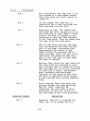
4.3.4
TIP Back-up and Restore Function Examples.
4.3.4.1
Back-up Example.
In this example the user wishes to back-up all data
and program files for an application called PAYROLL to the tape
cartridge. The application programs are located on the floppy
diskette in drive B. All of the program file names begin with
PAY and are followed by other identifiers such as INP, OUT, with
a file type of 'INT'. Example: PAYOUT.INT
All of the data files reside on the Winchester Hard
disk and have a secondary file name of FIL.
Exampl~: PAYDATA.FIL
The tape cartridge is new and has been inserted into
the unit. The sequence is as follows:
With TIP residing on currently logged
drive enter TIP (press return)
Screen Displays:
CODE:
I
T
B
R
A
V
D
ESC
(based on version 3.3 TIP)
ACTION:
IRITIALIZE TAPE
RETENSION TAPE
DISK TO TAPE BACKUP
TAPE TO DISK RESTORATION
DISK TO TAPE APPEND
FILE VERIFICATION
TAPE DIRECrORY
ESCAPE TO OPERATIRG SYSTEM
4-9
4.3.4.1
--Continued.
User Inputs:
I (press return)
tape is initialized
B (press return)
Prompt: FILE NAME:
B:PAY*.INT (press return)
files are backedup from disk to tape
and screen will
display each file
name as it is copied
Prompt: FILE NAME:
E:*.FIL (press return)
data files from hard
disk are backed-up
to tape
Prompt: FILE NAME:
(press return)
end of data marks
written to tape
and tape is rewound
Now the user discovers that there is an additional
file which must be added to the tape. The name of the additional
file is PAYROLL.ERR and it currently resides on the logged-on
drive. The user will re-insert the ·tape cartridge, invoke
TIP, press return, and from the menu:
enter A (press return)
invoke the append
function
Prompt: FILE NAME:
PAYROLL.ERR (press return)
the additional file
will be appended to
the end of the tape
Prompt: FILE NAME:
(press return)
this will cause the
end of data marks
to be placed at the
end of the new file
which was added
4-10
4.3.4.1
--Continued.
To obtain a printed list of the directory of the
tape, the user will enter a Ap before invoking the directory
command, D. After the directory has been displayed and printed,
tne user will press return to execute a warm boot and
return to operating system control.
4.3.4.2
Restoration Example.
A problem with the payroll system has developed.
The TAXES.FIL file has been inadvertently destroyed on the
disk and must be restored from the tape. The sequence, once
tne proper cartridge has been inserted into the unit is:
TIP (press return)
invoke TIP
Menu is displayed
R (press return)
invoke tape-to
disk restoration
Prompt: FILE NAME:
TAXES.FIL (press return)
PROMPT: IGNORE SOURCE DEVICE CODE, Y OR N?
If you want restoration of this file to be from tape
to the current~y logged-on drive, and the file was originally
backed-up from the same drive, respond with either Y or N.
If you want restoration of this file to be from tape
to the currently loggea-on drive, and the file was not originally
backed-up from tne same drive, respond with Y.
If you want restoration of this file to be from tape
to the drive (disk) from which it was backed-up, and that drive
is not the currently logged-on drive, respond with N. Restoration
will be from tape to the drive from which the file was originally
backed-up.
This next situation is one in which the user
discovers that a~l files have been lost on the disk and a total
restoration is necessary. Regardless of which drive was used
as the originating drive to back-up the files, the user wants
the whole tape restored to drive F. The sequence is as follows:
4-11
4.3.4.2
--Continued.
Invoke TIP (press return)
R (press return)
Invoke tape-to
disk restoration
Prompt: FILE NAME:
F:*.* (press return)
Prompt: IGNORE SOURCE DEVICE CODE, Y OR N?
Y (press return)
the entire tape will
be restored to
drive F
Prompt: FILE NAME:
(press return)
4.3.4.3
control returned to
operating system
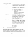
File Verification Example.
In this example the user has made some recent changes
to a data file called MASTER.FIL. The user is not certain if the
tape file has been backed-up since the last changes were made to
the disk file. The original back-up was made from drive E.
Invoke TIP (press return)
menu display
V (press return)
Invoke Verification
Prompt: FILE NAME:
MASTER.FIL (press return)
Specifying file to be
compared
Display: FILE NOT FOUND ON TAPE
user forgot that the
source drive was
made a part of file
name. Accurate file
name was E:MASTER.FIL
Prompt: FILE NAME:
E:MASTER.FIL (press return)
4-12
4.3.4.3
--Continued.
Display: FILES BEING VERIFIED
TIP will compare the
file on tape with the
file on drive E since
it was specified as
the source device
drive
Display: FILES VERIFY!
The files did match.
Had they not matched
a display would have
shown the addresses
where mis-matches
occurred
Prompt: FILE NAME:
(press return)
4.3.4.4
return to operating
system control
CP/M and MP/M User Examples.
Prompt: FILE NAME:
PAYROLL. * [G*l
This entry will result in
all files with a primary
name of PAYROLL to be
backed-up regardless of
their secondary names.
It also results in those
files being backed-up
regardless of user number
Prompt: FILE NAME:
*.ERR[GlJ
All files with a secondary
name of ERR from user
number 1 will be backedup
4-13
4.3.5
TIP Use Considerations.
The TIP program can utilize mUltiple tape cartridges
to store all of tne back-up files specified by the user. The TIP
program utilizes end-of-data and end-of-tape markers which
indicate whether the current tape cartridge contains the last
file or whether additional cartridges were utilized. No tape
labels are generated by TIP nor is the identification of the
user who did the back-up operation revealed. No information
concerning how many tapes make up a file are listed by TIP.
It is highly recommended that gum tape labels be
used to label each cartridge as it is used. The date that the
back-up was performed, who performed it, system configuration
and any other relevant information should be placed on the
label.
4.3.5.2
Documenting Back-up/Restore Operations.
Tne capabilities of CP/M and MP/M allow all output
lines sent to a user terminal to be echoed to the system
printer. On some operating systems this is done directly, while
on others, spooler action captures the output lines and causes
tne print action to occur later.
ALTOS recommends the use of Control P (Ap)
to engage the printer while using TIP. within TIP Ap
can be entered at any time except in response to the command
menu. This is the normal approach with CP/M.
TIP does cause a reduction in performance when
operating under MP/M. Under MP/M it is necessary to mask the
I/O interrupts while TIP is actively accessing the tape
cartridge. This requirement has two major effects:
a.
The MP/M time-of-day clock does not operate
while TIP is actively transferring data to the
tape, thus the clock will be "slow" after TIP
has been utilized.
b.
The performance of individual users in a multiuser environment will be substantially affected.
In a four user system each user could experience
a degradation of performance of up to 50%.
One way to minimize the effect of TIP in MP/M systems
is to create a single user MP/M system disk which contains TIP
and is only used for TIP operations. This will substantially
reduce the amount of degradation and will also keep other users
from accessing and altering data files which are being backedup on tape.
4-14
4.4
TIP Tape Recording Procedure.
The TIP system writes files to tape in blocks of
8,208 bytes. Contained within this block is a 16 byte tape
control block (TCB), which contains information describing the
file. The file data consists of from one to sixty four 128 byte
sectors as copied from the disk. If a file is over 64 sectors
in length, TIP will write additional tape blocks until all of
the file has been copied.
TIP utilizes the standard end-of-tape convention of
two file mark recoras on tracks 1, 2 and 3 to indicate that the
tape unit should rewind and continue on the next track. An endof-tape indication on track 4 signals that there are additional
tape volumes within the back-up/restore operation. TIP's endof-data indication is a file mark record followed by a blank
record and two additional file marks. When TIP encounters the
end-of-data condition on a restore operation, it indicates to
the user, by display, that the task has been successfully
completed.
The Tape Control Block format is as follows:
US Fl F2
00 01 02
/
/
F8 Tl T2 T3 00 LB SD RC
.. . .
08 09 10 11 12 13 14 15
us
The CP/M and MP/M User Number which
ranges from 00 to OF. If no user
number was specified the current user
is used as the default user number
FI-F8
Primary file name in upper case ASCII
TI-T3
Secondary file name in upper case ASCII
LB
Last block indicator
SD
Address of the disk drive from which
this data file was backed-up. The
value ranges from 0 to F which would
indicate disk drives from A to P
RC
The number of 128-byte sectors which
are contained in the 8192 byte block.
This value ranges from 1 to 64. If the
file does not utilize the entire tape
block then TIP fills the unused portion
of the tape block with OOH
4-15 (4-16 Blank)
5.
ERROR CODES, TROUBLESHOOTING AND PROBLEM DIAGNOSIS.
5.1
T1P Error Conditions.
The error conditions encountered by TIP fall into
2 categories:
a. User errors-specifying incorrect file names,
incorrect spelling, improper format when
entering commands
b. Tape media or tape unit problems-found by TIP
and not allowing TIP to properly perform a
valid user command
5.2
File Specification Errors.
If a user specifies an invalid file name, TIP
will respond with tne display: FILE NAME BAD, REENTER. If the
user enters a file name that does not exist, TIP will display
FILE NOT FOUND.
5.3
Inadequate
Di~k
Space During Restore.
If an attempt is made to restore files to a disk
that does not have suffic1ent space, TIP will inform the
user that restoration is being aborted and return to the
command menu. It is up to the user to ensure that sufficient
space is available. If an abort occurs, the user must insert
a new cartridge and restore, selectively, those files which
were not restored on tne previous cartridge.
5.4
'Full Tape Cartridge' Conditions.
TIP allows the user to back-up files to as many tape
cartridges as necessary. When multiple tape back-up files are
restored, TIP performs error checking to catch instances where
the tapes have been inserted into the tape unit out of sequence.
Tne display: UNEXPECTED END OF DATA indicates that a sequence
error has occurred. The user should restart the restore operation
using the proper sequence of tapes. The same display can occur
if the user extracts a tape from the unit while the unit is
attempting to back-up or restore a file or set of files. When
that tape is re-inserted at a later time, the tape is rewound,
but no end-of-tape or end-of-data marks are placed on the
tape since it was pulled from the unit prematurely.
5.5
Tape Media and Tape Unit Malfunctions.
TIP recognizes three error conditions that generally
indicaLe problems with the tape cartridge, tape unit or the
TIP software itself. TIP provides two types of error messages.
5-1
--continued.
5.5
A general error code provides a broad indicator of the type of
error which has occurred. A specific sub-error code provides
additional information as to the cause of the error.
5.5.1
General Error Codes.
5.5.1.1
TAPE COMMUNICATIONS ERROR, SYNTAX REJECT WITHIN TIP
This error code indicates that an invalid set of tape
movement commands were sent to the tape control unit by TIP. The
user should assume that the TIP.COM file has been compromised and
should go back to the original distribution diskette of TIP and
re-load TIP to see if the problem occurs again.
TAPE ABORT ATTEMPT WITH ATTEMPT
5.5.1.2
This error code indicates that an unrecoverable error
condition has occurred and that the tape media was moved. This
means that after 16 retries the tape unit was unable to complete
the requested operation. On a back-up operation this error
generally indicates bad media. A sub-error code will also be
displayed. During a restore operation this general error code
display means that after 16 tries tne block of data still could
not be read. Since the inability to read data is expected only
once every 100 million attempts, the error code generally
indicates a tape media or tape unit problem.
TAPE ABORT WITHOUT ATTEMPT
5.5.1.3
This error code indicates that an error has occurred
without the tape moving. Generally, another message would
fOllow. One common occurrence of this error display is when the
user invokes TIP without having the tape cartridge inserted in
the unit. Sub-error codes are generally included with any major
error display.
Sub-error Codes.
5.5.2
Following the general error code display TIP
will provide sub-error codes which provide more detailed
information about the error condition.
SUB-ERROR CODE
00
MEANING & SUGGESTED SOLUTION
The tape drive has executed an automatic rewind since the last TIP command
was issued. Return to the command menu
and proceed with the knowledge that
the tape is already rewound.
5-2
5.5.2
--continued.
01
A write operation was requested to a
write protected cartridge. Use of a
non-write protected cartridge is
required.
02
A TIP command was issued with no tape
cartridge inserted into the unit.
03
The tape unit did not respond to a
valid command. This is generally caused
by a hardware failure.
04-05
Not used
06
The Read-after-Write circuity indicates
an error in attempting to write a file
mark record. The tape should be reinitialized, the tape re-tensioned and
re-try the operation. If the same
failure occurs, try a new cartridge.
07
The tape unit aborted prior to
completion of a valid command. This
generally indicates a hardware failure.
08
A read command failed due to missing
data or file mark record. This is
usually caused by bad tape media. If
the same problem occurs with a new
cartridge, suspect a hardware failure.
09
A read command failed due to a "short"
record being encountered. Ensure that
the tape being read was created using
TIP. Cause could be bad tape media or
a hardware failure.
10
Same as 09 sub-error code.
11
A read command failed due to bad
vertical parity. This is generally
caused by bad tape media. If the error
occurs with different tapes, suspect
a hardware defect.
12
A write command failed due to a readafter-write verification error. Retension the tape and try the operation
again. If problem persists, suspect
hardware defect.
5-3
5.5.2
5.5.3
--continued.
13
A write command failed due to a read
data indicator not being detected prior
to the write operation being completed.
This is generally caused by bad media.
Proceed as in sub-error code 12 above.
14
A read command failed due to a file
mark being detected. This is generally
caused by bad tape media. Proceed as in
sub-error code 12 above.
Error Analysis.
When a problem develops with operations involving
the tape unit, the first step in troubleshooting the problem
is to make a dtermination as to whether the problem is with
tne user making bad input commands, tape media or hardware
failure. When the user is informed that an error has occurred,
the tape unit has already attempted recovery. For any Read or
Write operation, the unit has attempted 16 retries. When attempting a write operation, the unit, during each retry, will advance
the tape 3 inches to bypass possible bad media. If all 16 retries
failed this would mean tne tape unit had bypassed 48 inches of
bad tape. This is highly unlikely unless the whole cartridge is
in fact defective.
The tape unit utilizes three major design approaches
to insure the ability to read data:
a. Reads eacn block as it is being written using a
trailing read head.
b. Advances the unit past suspected bad media whenever write errors occur.
c. Uses a precise and clean signal during write
operations. The read-after-write function is
done with a 3db reduction in read head signal
strength. This is done so that if the readafter-write operation is successful then later
read only operations should occur without any
difficulties.
5.5.4
Tape Unit Status Codes.
The tape unit returns two status codes at the
completion of every operation requested by a program. One
status code is for the tape drive and the other is for the
tape interface. These status codes inform the callin9 program
5-4
--Continued.
5.5.4
whether the requested operation was completed successfully
as well as tne ending condition of the tape media. The
status codes are returned in the form of two status bytes
as follows:
DRIVE STATUS BYTE
Bit
Bit
Bit
Bit
Bit
Bit
Bit
Bit
INTERFACE STATUS BYTE
7 Reserved
6 File Mark Detected
5 Drive Rewinding
4
3
2
1
0
nOnn And Loaded
Beginning Of Tape
End Of Tape Warning
Auto Rewind Executed
Write Enabled
Bit
Bit
Bit
Bit
Bit
Bit
Bit
Bit
7 Reserved
6 Data Block Available
5
4
3
2
1
0
Command
Status
Current
Drive
Current
Track
The format of the Status bytes is as follows:
Bits
The status codes returned by tne drive are the
hexaaecimal representation of the Drive and Interface Status
Bytes. Depending upon the type of operation requested by the user
more than one indicator may be ON within the status byte. For
example, if the tape drive was powered-on and a tape cartridge
was loaded at the beginning of the tape, the Drive Status Byte
would be 15. The 10 bit indicates that tne drive is on and
loaded, the 04 bit indicates that the tape is at the beginning
and the 01 bit indicates that the tape is not write protected.
The user should break the status codes into their component
parts. The meaning of each bit in the status byte is defined
below.
DEFINITION
DRIVE STATUS
Bit 7
Reserved. This bit is reserved for
later use. It is always set to 1.
Bit 6
File Mark Detected. Whenever the tape
unit detects a file mark record on the
tape, this indicator is set.
5-5
5.5.4
--Continued.
Bit 5
Drive Rewinding. The tape unit is in
the process of a high speed rewind.
This flag stays set until rewind is
complete.
Bit 4
On and loaded. The tape unit is
powered-on and a tape cartridge has
been inserted into the unit.
Bit 3
Beginning of tape. The loaded tape
cartridge has been rewound and is at
the beginning of tape. When a rewind
occurs, the tape is rewound to the
beginning of tape and then advanced
to the load point. This bit shows that
the tape is at the load point.
Bit 2
End of tape early warning. The tape
unit has detected the early warning
hole in the tape, indicating that
approximately 48 inches of tape
remain before the phys1cal end of
tape cartridge. Only file mark write
operations are permitted when this
flag is set. The flag is reset when
the tape is rewound.
Bit 1
Warning flag. Since the last operation
the tape drive has executed an automatic rewind. This is caused by taking
the cartridge out of the unit and then
re-inserting it again. The program
must recognize that positional
integrity of the tape has been lost,
and that no operations which assume
a tape location will provide expected
data.
Bit
a
Write enabled. This flag tells the
program whether the tape cartridge
has the 'safe' indicator ON,
indicating the cartridge is write
protected. If this bit is set to 1
the cartridge is not write protected.
INTERFACE STATUS
Bit 7
DEFINITION
Reserved. This bit is reserved for
later use. It is always set to 1.
5-6
5.5.4
--Continued.
Bit 6
Data Block available. A tape read or
search operation has been successfully
completed and the data is available to
be read into the control unit buffer.
Bits 5 & 4
Command status. These bits indicate
the results of every tape operation.
The return codes are:
00 - Operation Successful
01 - The operation was aborted
without tape movement.
01 - Read operation aborted after
16 retries
11 - The specified input parameters
requesting an operation were
invalid. This is usually a
programming error.
Bits 3 & 2
Current tape drive. The tape unit
allows up to 4 tape units to be daisy
chained on the same data bus. These
bits indicate the selected drive.
Presently, only 1 MTU is available
to the user. These bits are thus
always set to 00 indicating
drive 1 is selected.
Bit 1 - 0
Current track. These bits indicate
which of the current tracks is being
accessed. When the end of a track is
encountered the tape unit automatically rewinds the tape cartridge and
selects the next track, unless the
tape was already on track four. The
bit indications are as follows:
00
01
10
11
5.5.5
-
track
track
track
track
1
2
3
4
Error Recovery Techniques.
Always suspect the obvious. Clean the tape unit, try
a different tape, retension the tape, check the error codes.
This will solve many read and write problems. Tape errors caused
by media problems usual~y result from the way the tape is stored.
Heat and humidity will greatly increase the incidence of temporary and permanent tape related errors. A good example of this
5-7
5.5.5
--Continued.
is the manufacturer's statement that a minlmum of 8 hours is
necessary for a tape to become 'acclimated' to a new operating
environment after the tape has been transported from one location
to another. Another cause of media problems is tape the being
wound onto a cartridge with variable tensions. If all of your
attempts fail, note all of the symptoms, note all the actions
that you took and call your distributor for assistance.
5-8
6.
STAND-ALONE MAGNETIC TAPE CARTRIDGE BACK-UP UNIT
(MTU-l) WITH ACS8000 COMPUTERS.
6.1
8200-CPU PCB and MTU-l.
The MTU-l package provides the components necessary for
modifying a~l the ACS8000 systems built on the 8200 chassis.
ACS8000 computers built on the 8000 or the 8100 chassis can not be
field upgraded to support the ALTOS Tape Subsystem. MTU-l contains
the following items:
6.1.1
•
MTU-l Chassis Containing the Mag Tape Drive,
#530-10809
•
Tape Controller Printed Circuit Board (PCB),
#330-10265
•
50-pin Internal Tape Interface Connector Cable,
#510-10529
•
Connector Caole with 37-pin Connector on
one end, and a 34-pin Connector and a pig-tail
6-pin Connector on the other end, #510-10292
•
50-pin Interconnect Cable Assembly, #510-10513
•
37-pin Interconnect Cable Assembly, #510-10286
•
Power Cord, #230-10233
•
Floppy Diskett Containing TIP and TIP Manual,
#580-10825
•
Blank Magnetic Tape Cartridge, #180-10267
Installation of the MTU-l.
Follow the procedure below when installing the MTU-l:
a.
With the power off, lay the ACS8000 on a flat
working surface. Loosen the six screws that secure
the top cover. Remove the top cover from the
computer.
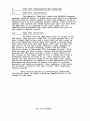
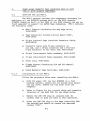
b.
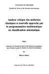
Refer to Figure 6-1 for circuit chips and connector
locations of the 8200 PCB for the steps below.
c.
Remove the Z80 CPU chip at location 14M. Be
careful that no pins are bent in this operation.
d.
Place the Z80 CPU chip in the Tape Controller PCB.
The notched end should be toward the embossed
letters "CPU".
6-1
I~j
J1!
[27AAJ
~
D~
L
_IJ
0
2- 4 A-A]
8
H
0\
I
N
JV
JW
~~
L'D20
13C
~~
130
SID
~~
-~
r-;OB I
'--~
~
===
~
~~~
~
~~~~
Pl
~~~
~~~
~~~~
~~~
~QD~
~~~~
~~~~
~~~
~QD~~
~~~
~~~~
~.~~
~~~
~~~
~~~
~~~
~~~
~~~
~~~
~~~~
~~~
~~~
~~~
Figure 6-1
~~~~
~~~~
~~~
~~~
~~~
~2J~
~~~
~GU~
~5=:J~
~~~
8200 PCB with Tape Controller PCB Mounted
6.1.1.
--Continued
e.
f.
g.
Locate and remove the white six-wire power connector;
it is to tne left of Matrix position 13K on the
8200 CPU PCB (See Figure 6-1).
Install the Tape Controller PCB onto the 8200
chassis in location 14M. The PCB makes two
interconnections on the 8200 chassis:
1.
The pins on the PCB will mate with the 40
pin socket at location 14M
2.
The pins from which the plastic connector
was removed in step (e) above will mate
with the 6 pin connector on the 8200
PCB when placed properly.
Insert the white six-wire power connector removed
in step (e) above onto the six-pin connector on the
rear of the Tape Controller PCB at P2. The red
wire of the connector should be on the right when
viewed from the front of the 8200 PCB. Be sure
the lip on the connector securely inter-locks with
the lip on the Tape Controller PCB.
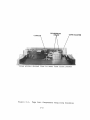
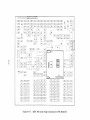
h.
Remove the 50-pin rear
connector (Figure 6-2)
and from the header at
(Figure 6-1). Save the
panel additional disk
from the 8000 computer
J2 of the 8200 PCB
hardware for next step.
i.
Attach the 50-pin ribbon cable supplied with
the Tape Controller to the rear panel of the
8000 computer at tne additional disk connector
shown in Figure 6-2 and secure it with the hardware from step (h) above.
j.
Attach the other end of the 50-pin ribbon
cable connector to the Tape controller PCB at Pl.
The red stripe along one side of the ribbon should
be on the right side of the connector when viewed
from the front of the 8200 board.
k.
Remove the 37-pin cable slot from the Parallel
Port slot on the rear panel of the 8000 computer
(See Figure 6-2); remove tne other end of the cable
connector (34-pin) from the header at J4 on the 8200 PCB.
Save the hardware for the next step.
1.
Attach the 37-pin slot end of the connector cable supplied with the MTU-l to the
parallel port slot on the rear panel of the 8000
computer and secure it with the screws from
step (k) above.
6-3
CONSOLE CONNECTORS
PRI NTER
1
2
3
4
CON N ECTORS
~
7
~
AUXILIARY
7 4--+-SERIAL
CONNECTOR
HARD DISK
CONNECTOR
ADDITIONAL DISK
CONNECTOR
Figure 6-2 Rear Panel of ACS8000 Computer
6-4
6.1.1.
--Continued
m.
Connect the 34-pin end of the connector cable
onto the header at J4 on the 8200 PCB. Connect
the 6-pin pig-tail to the six-pronged plug on
the Tape Controller PCB at P3. The pigtail
connector is keyed and can only go in one way.
n.
Attach the 50-pin interconnect cable from
the ACS8000 (additional disk) connector to the
rear of the MTU-l chassis. It is the only 50pin connector on the MTU-l rear panel.
o.
Attach the 37-pin interconnect cable from
the ACS8000 Parallel Port Connector to the rear
of the MTU-l Chassis it is the only 37-pin
connector on the rear panel.
p.
Replace the cover of the ACS8000 computer and
tighten the six screws on that hold the cover
in place.
q.
Install the power cord supplied with the MTU-l.
r.
Switch on the computer and the MTU power switch.
s.
Insert the tape cartridge. The front panel should
be lit and the tape should rewind to the beginning
of tape.
6-5
6.2
8500-CPU and MTU-2.
The MTU-2 package provides the necessary components
to upgrade your 8500 CPU system--ACS8000-l0 and ACS8000-l5.
Your upgrade k~t will contain the following items:
~.
MTU-2 Chassis Containing the Mag Tape Drive,
#530-10809
•
Tape Controller Printed Circuit Board (PCB),
#500-10762-001
•
l3-inch 34-pin internal interface ribbon cable
(8500 board to tape controller board) #510-10529
•
22-inch 50-pin internal connector cable
(tape controller to computer rear panel) #51010542
•
72-inch 50-pin interconnect ribbon cable, #51010513
•
Associated haraware
',e
Power cord
•
MTU-2 Upgrade k~ts for the ACS8~00-l0 will
have an 8 1/2-inch 6-wire power cable #51010658
Note 3 kinds of cables
Interface cable--Printed c~rcuit board to printed circuit
board connection
Connector cable--Printed
nection
c~rcuit
board to rear panel con-
Interconnect cable--Computer rear panel to U/K rear
panel connection
To install your MTU-2 to your system you will need
the following items:
o
Regular Screw Driver
o
5/16 open ended wrench or equivilent
6-6
6.2.1
Installation of MTU-2.
D1~connect the power cord on your computer.
Remove
the top cover by loosening the side panel screws with a
regular screw driver. Carefully, lift off the top cover and
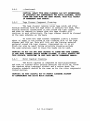
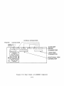
set it aside. When installing any ribbon cables, be sure that
the red strip is to the right as you face the coaputer. Refer
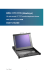
to Figure 6-3 when installing your upgrade kit. Follow the steps
be~ow to install your MTU-2.
a.
If you have an ACS8~BB-lB or U/K-lB, you have a
hard disk controller board on the right side 85BB
board. You will have to remove the 5 nuts that
secure the hard disk controller board to the 85BB
board to access J5 Pinning for the MTU controller
board. You do not have to remove any cables connected to the hard disk controller board--after
removing the nuts, simply fold the controller board
to the rear of the computer.
b.
Insert the l3-inch 26-pin interface cable at
Matrix position J5 on the 85BB board.
c.
Place the Tape Controller board onto the standprovided on the left side of the 85BB
board as you face the front of the computer.
Secure the nuts finger-tight and then snug with
the wrench. Do not overtighten •
o~fs
..d.
the l3-inch interface cable installed in step
(a) above over the Tape Controller board and insert
into the Tape Controller board at matrix position
J5. Verify that the red strip is on the right
as you face the front of the computer.
, er.
Connect one end of the 22-inch 5B-pin cable connector at J2 on the tape controller board and the
other end into the rear panel of the Computer at JC.
Secure with nuts and screws provided with your kit.
f.
Fo~a
If you have an ACS8BBB-lB or and U/K-IB take the
6-w1re power cable connector and insert one end
at PIon the tape controller board and the other
end atJ3)on the power supply inside the rear panel
of the ~mputer.
It you do not have a hard disk controller board'
connected to the 85BB~b-oard, there are two power
connectors bound together by plastic wrapping
Carefully cut the plastic wrapping that binds
the 2 white power connectors on the 85BB board.
6-7
===:::J1J2
<-I_ _ _ _ _--'IJ3
CI
f
R~um
On
DD
11J
,..a •
]
=~
GhJ
~
8U:j-~.J
=
J2
[EJrn~rn'BU!JJ 'J[}Q::)JjQQI]~rn~rn
DDQJ~QJGf:JI.D Q~JJ>iVJQJG£:Jrn~lJ)
~QJ~rnGLJQJ O~GQlJ)GOlJ)~ll
ODQJ\ 55 IQJGf:Jrn U~QJCKJrnG£JQJ~lD
GDQJeillUJGUOJ
OCillaJ~m~QJ~rn
DDrn[j[JlJ)~W ll~UJQQrn~lD~rn
~rn~rn~:}ll JOQ:jjl)DfJruLEJQJ, "2~ru
~rnGIJlD\ IC]W OL!QJJJGUru\ IF Irn~Q)
Figure 6-3.
ODZJrn~rn~QJ
OillJrnu:;]rn~rn
J~w~rn\ ('Lrn
J[gJ]~lDGUQJ
O[EJrn~rn~o
o~rn~lJ)~O
ocarn~wGUo
o~rn~rn~o
JGLJrn~WGhJlJ) O~rul
AN
Iru~O
J[3LIru~wUhJrn O~lD~lJ)~O
1.1\ "1.J]UJChlrnU.dll J~Q)lliJlD[illO
,IGLJlDG;:Jrn~J)
JI
1M
IllJGLlrn~
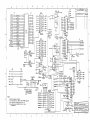
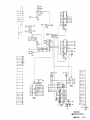
8500 Central Processing Board and MTU-2
Controller Board.
6-8
R.5
6.2.1
--Continued.
h.
When fully extended, insert the end connector
into PI position on the Tape Controller board.
Be sure that the red wire is to the right
as you face the computer.
i.- If there is no Hard Disk controller, let the
other 6-wire connector rest in the computer
so that is does not obstruct any ICs or interfere with the power supply or the fan.
~
Secure the tape controller board to the 8500
board in the four standoffs positions with
the nuts provided.
k.
Attach the 72-inch 50-pin interconnect cable
from the rear panel of the computer at JC
to the rear panel of the MTU-2 Chassis.
1.
Verify all the steps above.
m.
Before replacing the top cover install the power
cords and check to be sure the system work properly.
6-9
Rear Panel Interconnect
~
Fan
I
JT
...-------.
JB
JD
JX
JE
I I
JU
JY
JV
JZ
Fuse
85i1i1-LBil7
Figure 6-4.
Rear Panel of
6-1~
ACS8~~~
Computer.
J
5
6
7
8
2
3
4
P3
CI
CDt)14
(0' 1)1 ~
I~PF .~ M2J.
"),...........L.._ _
.--~
14!
_ _ _ _--f,;;!..j
I
'>---+---__-.;;.:.!:------""""i
2
(O~12~~---~~~---------~
D
3
4
(C!l c
(D~ 7~~-----r~~-----~
ronl~'>--+------~~-----~~
CA¢)30
~1)31>-~----~~-----~
g
(A 3) ~ ..~-+---_--!:~-----"'"'1
(A4)34
CA 5-"'3" )--------..;~--------..&..Kj
(A 6)3 -....J....--_-7-=--------~l=l
DI
,
II
>-.,...-t-""-- 0 94
16
05
>-f''''---
06
D7
>+~-DB7
74LS244
WR42Z>--~--~~~~-----~
RESET~~>-~--~~~~------~
WAI HE- 2''O--....:....----..v~I'I:._----_&.::.I
vee
40
ADD5EL
(185)
-5 3)
5
vee
5yce
)3
MtO
A ¢--1A.
A I --2 B
GNO
Y I t:.-!-=14"-+----+----f--,
Y2~
1:
AODSEL
.-----' I
vee
PI
P'vCC
L-ouT GI
.
WDS J48
~---1-41"""e5""""}-6""'Ic-7}"-8-~""'"~vec
RNZ
'36';'
1,=,57,9,11,1 3,15,11, 19,
NOTES:
A
I. i.JNlESS OTHER WISE SPECIFIEO:
0
OAv.. 4 ."'
C.C.P.u.(Z8O) SIGNALS ARE NOT
PII
SLOi 2
REFERENC~::
WITH
FLG*
2 i7
74lS240
D.H.
9 .... xc
12
~
1
2 M~
I.
74lS240
-
I
." RXC'
TX®~
r
~1:-.ul'4l.-+-_""'"
~rp;':....:.-5-+---,
?I:.,;::- M4
0\",~7
16 xC
I .~O
oj'
02
A0~ A~ 2651 0.;;
A I~AI
0
A
L __________-.!.l·~
,~:iR ESET _ 0"
B¢
-DB I
~B 2-
~8
I
2
5
6
7
I"",
7
... 86
II
9
-0 B7
B
~
17'11 <;?40
1013
-I
(ID~ n~
IJI.I..
RT~~
A
I...I'-'_.NO
___.........~
e
ALLOY
ENGIIlEERING COMPlIIT
OYO
4
.• t<.
7
.... 84
-0 85
2-71R/W O~
085
08 6
r - - - ------'-,-'<1,z.s fL.1. 0 19 DB 7
OHSEL-f __ J~
1
DZ-eO
1-.'.""
s
15
~8 :3
Ewst
ROY,
13
,e,
..(\84
LPSf
COORDINATE S
R>
.I~
l.!1
j
85'(*14
WHDI
FuPj I
A. All RESISTORS VALUES ARE IN Q-iMS·AND ARE I/~W,!:5r.
8.ALL CAPA:ITURS vALUES ARE IN MICFfCFJ..;; ... ['S
~3
RDS-:i38 /' :
,..i-
2 ~23,2 5,27,29,31,33,
35,37,39,'11,4 3,~5;47,
",9
4.7 K
PuP
19 8
1012
I 4.7 K Pu
~/-T'---+--+-1r-..,.1.-ole"",,-M 3
J
vee
llZ
vee
74LSI:38
(leG)
0
2
vq. ~
A3-t,:2A YE~7
- -....."~~28LJ.YJi:::'---t--'
~MI5~78AJ
~ ~NPG-i
~ ~~27~
IOOVOC
E2 EI
GNO 2
A2~C
~J
C4THUR C8
.IUF
I
C
...--_......
114
~-7 y~I~I----+-~_+--~
~---~6BL,-· . '(9:-JI~OH-+_------'
RO oM---~C1_-
~-
TIi .-
~M14
I/O Y::~
:)6
1
-
'~I
T2~~ 8212
II DHSE)J*
\-+1-""----1] B7
WR *-_-!!::i~_
:~
~I'"'
1. l~bS2
~-+:....:.I---DB6
l
,
1
'-':;:46TR2*
:)32SL4 ..
+----+........---nB~
1-+-'----0 B5
A5--~
P~
I
I
'~50TRlf
17
10
c
A
WR
8
Q
H.!.~-DB3
74L5244
,
~-
7D
I aD
Q
f-+..!..!.-..---r:... B I
0
1
1
(
PI
Q-~12~1--~'7~ZBSL~
Q Is
' .... 3QSL21
0-:;::.4_-'
I----t"'-----{; B 2
DE
07
+12 6)
PIN
I---+"''---DB¢
10115
,I
~3KE'(
Z-80 180· -+--t--i
74lStO
MI3
03
..,12
QI~
D~~D
DSDB7
I
B ROTATED
Qzl6-
D81--;J2D
D92 ----;;1~ 0
liOl
38
39
RD~211~~---~~~~~----~
DB0~ID
Da4~
DB5~~
)~3
r+
~
1145
0 e3
>+!:::-- 085
>---+"'-- 0 86
28
29
1~RQ~2C>-~--.-~~~---~
w.o..s. ...
A
2
113
M9
27
CA 1; 31'>---.!-----..;~-------~
15
.2.~
>+=~-DBI
D:3
04
18
19
23
25
(A 2)3'2~'>-~---=-.::------,~
D¢
>-"""';":=---D82
17
_------~Ir__
>--+'"'''--- DB¢
D2
5
6
ro~ 9>~~---~~--------·--4
(~) ~~~----~~~------~~
c
-ovec
r::nl·~
JI1
----!71
5
?
INTE~F t.C~
- '." . :::..
'H I OF
!c:r:!;-(y~~
I
'·'8
j:
C2
~
rlI
;T-2~
I-I f}11l~~Dl
-3
-+
-5
r4~
~Q
7C
-12 II
+ '51/
+ 51/
r
J/- {, -1---+-
l'io,l 4"
RP/1
+.U:: ..1+5"
1
,r-p~P:1:---.-------"""
~~IIl
~S'
1>1
1>1.
tz-3_-,
3
Q3Q4F-'21---SLl
.0 Q5 8
SL2
Q(, 'T
Tl'-1
QT 10
T R2.
II
D~ ~ I/o])
TP~A IT ----....;.:....t7i
---d- 5D
1>4
~ bD Zn
.Db -----1. 1 D
PS
+ 12"
Q8 15
D7 -----1!. 8D
CI
".f
ql-
Q2-
b
l
TPwR
b 6CP-:--IOIIIR
AB3,----i14C 1>3_ _ _ HJ)~EL
SL4-
'I ~~} 8Z12.
+s
~MD
'14LSOO
-l! 5T6R c:...
71-l532-
~:l:>-!-9+-_ lol:.D
14
TPM>~
MitRE SE.T--2J-:.q~. ~QClI"~_+-_ _ _ _ _....J
i'4Ls 00
1'+lC; 2.40
Ai; --'- A
Y6 o:-='S'-+----.
A81 ---* 13 3C Y1£G:""'II..'-+----ll--.....
AB2-1 (
--4
D4J
It
Q I t = / - : ' - ' - - - - - - - REV
D I --!!...2.D
Q2 ,
FWD
D2. ~30
Q3 4
H5P
03 ~ 4D
Q4 2.,
WEN
7 5'D 28 Q5~
D+ ----':-8
D5 ---4- bD
Q{,f.=o'l!--.+_-+---- RWD
D6
7])
Q7 ~
Y2. 0
741.S1S8'13 D,
'I4L")-"''-t---if---+--+----+----l
y~"'\IO
Y6D
Y7
o-L
-----+
----.-.!! 8D
D7
Q8rl5'~+_-+-'1'_1IB t!J
r
I~ D~
8Z12
J
+5" I
;)1
J5-B
-8
-i?8
TPWAIT
TPDMA
IOW~
-32
M~tES€T
-""I-
TfwR
-26
TP~n
-e3
Do
-I']
'/)1
1)3
-Z/
D4-
c..
-18
-13
1)5
Db
D1
I
RPI-
~
2 ~
41K
AB~
-31
Af3,1
-~
AB2.
-i?7
At!.}
-16
AB4
AB5"
ABb
-/2
-7
-"f-
075-2
ABl
YI4-
-+
~DY
~~~S
wreD
I'
.,-+~-+-------------+~--~-:~; --;?~
,-----,
+--~II Ie
WDS --+-~f--+--+----.,;";:q~ rXc. noo~
'7+Lc;2.~O
~
RtJl _-+-+-<6--_ _+---=z.<:tt~ RXD
RDS
2f: iiXC.
DAD
-34
:!l.-2.
SLD
Il
-ZQ
1000 pt
c3
~------------~
t>2.
-II
-'-
1'1-
IOJ.D
-5
-15
~MD
..J..! STBR
SLG
7+/1"
1'80
A~ I
,,&2.
I'!>
AI
l\D5El
11
£f
II
•
1>41
DO 27
D 1 28
1) I
FL..~
-s
L'PS
fUP
t.sy
-10
RN
D+
ffl
~
2.
I)
EIoI~
-1(.
-II~
Ile.V
-2.0
Fwl>
-2.2.
WEN
-u
SLI
-18
51.2-
SL.4
-30
-31
-54
-3~
D.\D
WDE
OS
06
1
0'-
D7
8
bl
.7..+0 ,
t--'-".'------'I~If.~....
B)o:iO~--WNc
GiN))
RTSl-"l=!--'1
2~51
SL/4
«Ni
RbS
'
T}(»
-.24-
HSP
D3
D+
05
6§
-It
-14
f,VlJ)
02.1----:-'-'_1>2
2C»3
L.--_ _ _~a:!f' REseT
~
f--D'~D7
14LS2..40
R;;;V D-'-I~,---. . .
I'Ia. OC.D
t\O
10
IS
TIt
~1>+
L-DS
-(,
LD...r ,
7+LU~
7~
-3'
-40
-~
-4+
w,,~
-+,
-+8
TlI..l0
WJ)S
WOE.
nl
'Jz-SO
~
S'CHE"MrJrIC
~nD/ ~ 0I9IaA!' CON~~
B$CJCl'- 00/1
J'2. -1 il,,,,,
.7Z.-41 all (1...-.
,-..l~J