1
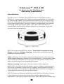
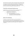
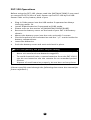
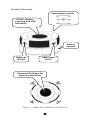
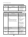
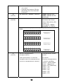
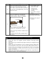
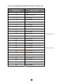
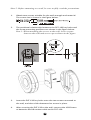
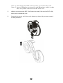
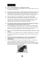
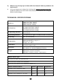
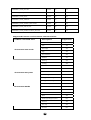
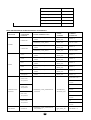
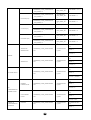
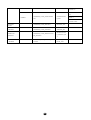
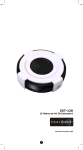
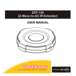
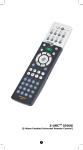
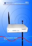
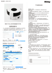
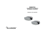
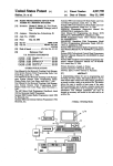
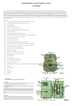
ZXT-120 (Z-Wave-to-AC IR Extender) Firmware Version: V1.0, V1.1, V1.2 1 Table of Contents Introduction .................................................... 3 Controller and Gateway Requirements ............ 4 Built-in IR code library .................................... 4 Glossary .......................................................... 5 ZXT-120 Operations ........................................ 6 Product Overview ............................................. 7 Z-Wave Remote Control ................................... 8 ZXT-120 Information ....................................... 9 Listening Mode Change .................................... 11 IR Code Selection ............................................ 12 IR Code Learning ............................................ 13 Reset ZXT-120 to factory default........................ 17 INSTALLATION ................................................ 18 MOUNTING THE ZXT-120 TO A WALL .................. 18 WIRELESS INFORMATION ............................... 21 MAINTENANCE................................................. 21 FREQUENTLY ASKED QUESTIONS .................... 21 Z-Wave Frequently Asked Questions ................... 21 TECHNICAL SPECIFICATIONS .......................... 23 CHECKING ACCESSORIES ................................ 28 FCC NOTICE .................................................... 28 WARNINGS ...................................................... 28 CAUTION ........................................................ 28 WARRANTY ..................................................... 29 2 Z-ExtenderTM ZXT-120 (Z-Wave-to-AC IR Extender) Operating Instructions Introduction The ZXT‐120 is a Z‐Wave to IR extender for air‐conditioner (AC), (Figure 1), it works with any Z‐Wave compliant gateway or controller by translating Z‐Wave Thermostat Commands to AC IR control code. User can select the IR code from the built‐in code library of ZXT‐120, or use learning function, by using Z‐Wave Configuration Commands according to the parameter table. ZXT‐120 is also with built‐in temperature sensor which allows gateway or controller to get the current room temperature. Figure 1 ZXT-120 ZXT‐120 can be configured as either “Frequently Listening Routing Slaves” (FLiRS) or “Always Listening” node after exclusion process (before inclusion process). FLiRS node type is for battery operated applications and it will enter sleep mode frequently in order to conserve battery consumption that can provide the flexibility if there is out of 5Vdc power source. Also, user can place the unit in anywhere at home. Always Listening node type is for the needs of fast response application. It works with 5Vdc power source. Always Listening node can act as a repeater, which will re‐transmit the RF signal to ensure that the signal is received by its intended destination by routing the signal around obstacle and radio dead spots. ZXT‐120 supports Network Wide Inclusion (NWI) and Explore Frames. It also supports Z‐Wave networks with multiple gateways and controllers. Like every Z‐Wave accessory, user will need to include the 3 ZXT‐120 into their Z‐Wave network using the primary controller. Then, the user can use either the primary controller or secondary controller to configure and setup the ZXT‐120 using Z‐Wave’s configuration command class. Once the configuration and setup is complete, the controller can use Z‐Wave “Thermostat commands class” to control their IR‐controlled air‐conditioner through the ZXT‐120. Controller and Gateway Requirements The ZXT‐120 can work with any Z‐Wave compliant controller or gateway supporting the following Z‐Wave commands. - Configuration Command Class - Multilevel Sensor Command Class - Thermostat Command Class Thermostat Mode Command Class Thermostat Fan Mode Command Class Thermostat Set‐point Command Class Built‐in IR code library The Built‐in IR code library supports most of the popular air conditioner brands in the market. Z‐Wave gateway and controller does not need to have any IR control code knowledge. User can use Z‐ Wave controller or gateway to select the IR code according to the ZXT‐ 120 code list separately provided through Z‐Wave configuration command. 4 Glossary Device or Node Inclusion Exclusion Remove Z‐Wave Network Primary Controller Secondary Controller Inclusion Controller Devices and nodes are all terms to describe an individual Z‐Wave device. These are all interchangeable when setting up your Z‐Wave network. Add a Z‐Wave device to the network. Delete a Z‐Wave device from the network. To take a device out of a group, scene or association group while that device still exists in the same Z‐Wave network. A collection of Z‐Wave devices is controlled by primary and secondary controllers operating on the same system. A Z‐Wave network has its own unique ID code so that controllers not in the network cannot control the system. The first controller is used to set up your devices and network. Only the Primary Controller can be used to include or delete devices from a network. It is recommended that you mark the primary controller for each network for ease in modifying your network. A controller containing network information about other devices within the network and is used for controlling devices. Secondary controller is created from the Primary Controller and cannot include or delete devices to the network. A controller containing network information about other devices within the network and is used for controlling devices. Inclusion controller is created from the Primary Controller in a SIS enabled Z‐Wave network. Inclusion Controllers have the ability to add and remove devices from the network. 5 ZXT‐120 Operations Before using the ZXT‐120, please read the [INSTALLATION] if you need to mount the ZXT‐120 to a wall. Power up the ZXT‐120 by the USB Power 5Vdc or Dry battery AAA x 3pcs. • Plug‐in 5Vdc power into the USB socket if operated at Always Listening mode. Or • Install 3xAAA batteries if operated at FLiRS mode. • Please refer to the section of [MOUNTING PROCEDURE]. • Remove the battery cover on the back of your ZXT‐120 battery chassis. • Mount the battery cover into the main unit with 2 screws. • Check the polarity of the batteries and the "+/‐" marks inside the battery compartment. • Insert the batteries. • Push the battery cover and main unit back in place. L CAUTION (battery and power adaptor safety) − Use new batteries of the recommended type and size only. − Never mix used and new batteries together. − To avoid chemical leaks, remove batteries from the ZXT‐120 if you do not intend to use the remote for an extended period of time. − Dispose of used batteries properly; do not burn or bury them. (Please carefully read through the following then store the manual for future reference.) 6 Product Overview Temperature sensor “PROG” Button, Learning and LED Indication Battery chassis External IR Port USB Power 5V DC Surround IR Output for top and 4-directions Figure 2 PROG Key and IR Port of ZXT-120 7 Z‐Wave Remote Control 1) 2) 3) 4) 5) Select your operation mode; please refer to “Listening Mode” section. Include or Exclude the unit from the existing Z‐Wave home control network with your primary controller. ‐ Refer to your primary controller instructions to process the inclusion / exclusion setup procedure. ‐ When prompted by your primary controller, click once on the PROG button. ‐ The primary controller should indicate that the action was successful. If the controller indicates the action was unsuccessful, please repeat the procedure. User can use either primary controller or secondary controller (should support configuration command class) to setup the ZXT‐ 120 AC code by the parameter 27 (IR code number for built‐in code library), please refer to code list for the parameter value then setup your AC control code. Once the configuration and setup were completed, the controller can use Z‐Wave “Thermostat commands class” to control their IR‐controlled air‐conditioner with the ZXT‐120. You can record down your device code under the below table for future reference after setting up the ZXT‐120 correctly. AC device programmed to your ZXT‐120 Code no.: 8 ZXT‐120 Information How to get the NIF “Node Information Frame” on ZXT‐120 (Inclusion) Step 1 Setup Key LED Indication Status on ZXT‐120 Press the PROG button on the ZXT‐120 • LED flashes once then stay off (ZXT‐120 will report the supported command class) Parameter No. and Parameter Value of configuration command Parameter Definitions Parameter Value Number 25 Indicate a location for IR code 0‐22 (0x19) learning and start learning (0x00 – 0x16) 26 Learning status register 0x00: Idle ‐ this IR (0x1A) channel is idle (default) Note: 0x01: OK ‐ the latest The status value 0x01 and learning process 0x04 will be reset to 0 when successful and the ZXT‐120 receive a get completed command to this parameter 0x02: Learning ‐ the ZXT‐120 is busy processing previous learning request 0x04: Failed ‐ the latest learning request failed 27 IR code number for built‐in Refer “Code list” for (0x1B) code library details 28 (0x1C) External IR Emitter power level 32 (0x20) Surround IR control - to avoid the IR interference by disabling the surrounding IR emitter if 2 9 0x00: normal power mode 0xFF: high power mode (default) 0x00: disable Surround IR Emitters 0xFF: enable Surround IR Emitters 33 (0x21) 35 (0x23) 37 (0x25) air‐conditioners in a room are used - extend the battery life by disabling the Surround IR Emitters AC function “SWING” control (default) 0x00: SWING OFF 0x01: SWING AUTO (Default) Learn location status Bit mask = 1, learn location has learn data. Otherwise, Bit mask = 0 See figure “Learn location” as below On below example, location 1, 7, 8, 12, 16 are learned data. 7 6 5 4 3 2 1 0 1 0 0 0 0 0 1 0 7 6 5 4 3 2 1 0 0 0 0 1 0 0 0 1 7 6 5 4 3 2 1 0 0 0 0 0 0 0 0 1 7 6 5 4 3 2 1 0 0 0 0 0 0 0 0 0 Bit Mask Byte 1 Location 0‐7 Bit Mask Byte 2 Location 8‐15 Bit Mask Byte 3 Location 16‐23 Bit Mask Byte 4 [Reseved] Figure: Learn location Sensor temperature Temperature offset compensation value. (This parameter is used to Formula: compensate the temperature Display temperature error at temperature sensor) = sensor reading value + offset value (unit = degree C) o 0x00 = 0 C (Default) o 0x01 = 1 C o 0x02 = 2 C o 0x03 = 3 C o 0x04 = 4 C o 0x05 = 5 C 10 o 0xFF = ‐1 C o 0xFE = ‐2 C o 0xFD = ‐3 C o 0xFC = ‐4 C o 0xFB = ‐5 C Parameter Table L Mapping Information − − BASIC Set Value 0x00 will map to Thermostat mode Off 0x00. BASIC set Value 0xFF will map to Thermostat mode Resume 0x05. Listening Mode Change (default mode is FLiRS) ZXT‐120 can be configured as either “Frequently Listening Routing Slaves” (FLiRS) or “Always Listening” node after exclusion process. FLiRS node type is targeted for battery operated applications and it will enter sleep mode frequently in order to conserve battery consumption. Always Listening node type is targeted for the needs of required a fast response application. Important: It is not allowed to changing ZXT‐120 operation mode without exclusion process (do not change ZXT‐120 operation mode while ZXT‐ 120 is included in a network). How to switch ZXT‐120 listening mode from “Always Listening" to “FLiRS" (or vice verse) LED Indication Status on ZXT‐120 Step Setup Key 1 Press and hold the PROG button on the ZXT‐120 for around 5 seconds • LED stay off 2 Release the button and then press the PROG button 3 times within 2 seconds • LED flashes twice then stay off 11 (ZXT‐120 set in FLiRS mode) OR • LED flashes four times then stay off (ZXT‐120 set in Always Listening mode) IR Code Selection ZXT‐120 is with built‐in IR AC code library, user may select the IR code using Configuration Command Class. LED Indication Status on ZXT‐120 Step Setup Key After included ZXT‐120 to Z‐Wave controller or Gateway, go to device setup for configuration on gateway or controller. ‐ 1 ‐ 2 Input parameter number “27” and parameter value (please look up the code list of ZXT‐120 according to your AC brand). Then complete the configuration process. 3 Press the PROG button on the ZXT‐ 120. (this step apply when using ZRC‐100 or other portable controller for set up, if using gateway, user can skip this step) • LED flashes once when ZXT‐120 receives the configuration setting Go back to the control page of ZXT‐ 120 on the gateway and try the function such as (cool, temperature set). • LED flashes once every time it receives a command from gateway 4 If the air conditioner does not respond to the command you set on Gateway (Cool, Heat, Auto, Temperature set etc.), repeat step 2 and 3 to select the next code on code list. 12 L Important Information − Different brand or model of air conditioner has different function. For example, some air conditioner only support o o o temperature set from 18 C‐30 C, if user set 17 C on gateway, ZXT‐120 will not respond. − There are more than 1 code for each brand, some does not support heat, if user selected a code that does not support heat but the original air conditioner supports heat function, please continue to try next code until the correct one is selected. − If none of the code works on the target air conditioner, or the air conditioner brand is not shown on the code list, please select code “000” for IR code learning (refer to instruction of IR Code Learning) IR Code Learning In case none of the code on the code list works for the targeted air conditioner, user can use IR code learning function using configuration according to below steps: LED Indication Status on ZXT‐120 Step Setup Key 1 Go to configuration setting page on the gateway or ZRC‐100 and input parameter number “27” and parameter value “000” to select the dedicated AC code number “000” for learning. Look up below mapping table (value 0‐22) for learning, and decide the IR setting you intent to learn next. 2 3 • LED flashes once when ZXT‐120 receives the configuration setting ‐ For example “22°C, cool” which matches value “5” (IR code to be learnt will locate at “5” in ZXT‐120). Set your original air conditioner remote at “22°C, cool” and turn it off. (Besides temperature and mode, you may set other desired settings, such as Fan, Swing etc.) Go to configuration setting page on the gateway or ZRC‐100 and input parameter number “25” and 13 ‐ parameter value “5” (in this case). 4 Press the PROG button on the ZXT‐ 120. (this step apply when using ZRC‐100 or other portable controller for set up, if using gateway, user can skip this step) • LED flashes once when ZXT‐120 receives the configuration setting • ZXT‐120 is ready to learn Aim the original air conditioner remote at ZXT‐120 according to below position within 1‐3 inches LED flashes twice if learning is successful. LED flashes 6 times if it’s failed. 5 Press “power on” button on the original air conditioner remote. If the learning is failed, repeat step 3 to step 5. To learn next IR code, repeat step 2 to step 5. L When you encounter problem, check followings: − Make sure your original remote is switched to power off. − Press the key on original remote before learning mode timeout. − Keep away from incandescent light and direct sunlight during learning. − Make sure IR Transmitter of your original remote alight with learning diode of ZXT‐120, you may also slight adjust closer or further away the distance of two devices. Some of remotes the IR transmitter in hidden behind lens and may not installed center of remote. − Make sure the power is good on both devices, especially the original remote. Use fresh batteries. 14 IR Learning Mapping Table (Parameter number 25) Parameter Value Thermostat command (Location) & IR setting 0 OFF 1 ON (resume) 2 19°C cool 3 20°C cool 4 21°C cool 5 22°C cool 6 23°C cool 7 24°C cool 8 25°C cool 9 26°C cool Default Cool 10 27°C cool 11 28°C cool 12 19°C heat 13 20°C heat 14 21°C heat 15 22°C heat Default Heat 16 23°C heat 17 24°C heat 18 25° C heat 19 26°C heat 20 27°C heat 21 28°C heat 22 Dry mode 15 L Important Information After all learning completed, user can go back to the ZXT‐120 control page on the gateway for normal operation. − On the gateway UI, user can only use the temperature range from the mapping table, OFF, ON(RESUME), COOL, HEAT, DRY, If user press the button of FAN, or other function on the gateway UI which is not listed in above table, ZXT‐120 will not respond. − If user only learnt ON, OFF, or part of the settings according to the above table, ZXT‐120 will send the learnt data to the air conditioner only. For example, user only learnt ON, OFF, 22°C Cool, 24°C Heat, ZXT‐120 will not send IR data to air conditioner if user set 27°C Cool on the gateway. − ZXT‐120 has been pre‐defined default cool at 26°C, default heat at 22°C, when user press Cool on gateway without setting temperature, ZXT‐120 will send the learnt data of 26°C Cool to air conditioner. When user press Heat on gateway without setting temperature, ZXT‐120 will send the learnt data of 22°C Heat to air conditioner. − There is only one code for dry mode, user can set it at any preferred temperature. − User can still use gateway to set up scene and schedule with ZXT‐120, for example, to have AC turn on at 23°C every day at 7pm, 25°C at 11pm. Just make sure the set code is learnt. − The learning mapping table is for split air conditioner which remote control is with LCD display. For window type air conditioner (which remote control is without LCD display), the mapping table with temperatures do not apply, due to different type of IR control protocol. However, user may still use the OFF, or ON/RESUME, DRY key for learning. (Because the POWER key on the original remote without LCD display is toggle, user can choose either ON key, or OFF key to learn Power key, after learning is done, press once to turn on the air conditioner if the air conditioner is OFF, press once to turn off if the air conditioner is ON) 16 Reset ZXT‐120 to factory default Press and hold “PROG” button for 10seconds on ZXT‐120. The LED will flash twice until reset process is completed. Note: This reset step will not affect the operation mode of ZXT‐120, user should refer to “Listening Mode" section if you want to change the operation mode. L Information − If you are using Gateway or other Z‐wave controllers to operate ZXT‐120, Please follow the instruction from the gateway or other controller. − You can check either the specifications in the manual of your ZXT‐120 or also check online at www.remotec.com.hk for a full list of products that can be used with your ZXT‐120. 17 INSTALLATION MOUNTING THE ZXT‐120 TO A WALL MOUNTING LOCATION PRECAUTIONS • Before mounting, check the material and structure of the mounting location. If the location does not have the proper material or structure, the ZXT‐120 can fall and cause injuries. • Use commercial items that best match the wall structure and material for the screws and other fixtures. • Do not mount near a kitchen counter, humidifier, or other location in which it can be exposed to smoke or steam. Doing so could cause a fire or electrical shock. • Do not mount in locations with high humidity or large amounts of dust. Doing so could cause a fire or electrical shock. • Do not mount to locations subject to high temperatures, high humidity, or exposure to water. Doing so could cause a fire or electrical shock. • Do not mount to locations subject to large amounts of vibration, large jolts, or large forces. These could cause an injury if the ZXT‐ 120 falls and breaks. MOUNTING PROCEDURE PRECAUTIONS • Do not modify parts or use the ZXT‐120 in ways other than its intended use. Doing so could cause the ZXT‐120 to fall and result in an injury. • Be sure to fully check that there are no electrical wires or pipes inside the wall before mounting. • If any of the screws are loose, the ZXT‐120 can fall and cause an injury. Do not mount the ZXT‐120 with the screws still loose. • Check that the two screws mounted to the wall are fully inserted into the key holes of the ZXT‐120. Otherwise, the ZXT‐120 can fall and cause an injury. • Do not mount the ZXT‐120 so that it sticks out from the wall edge. It could get hit by people’s bodies or objects and cause an injury. • Supplier will not be liable for any accidents or injuries that occur due to improper mounting or handling. • When mounting, be careful not to get your fingers pinched or injure your hands. MOUNTING PROCEDURE The ZXT‐120 can be mounted to a wall or wooden racks using the two key holes in the bottom case. Note 1: The reception sensitivity varies depending on the antenna direction. 18 Note 2: Before mounting to a wall, be sure to fully read the precautions. 1. Obtain two screws suitable for the wall strength and material. The screw size is shown in the figure below. 2. The positional relationship between the ZXT‐120 key holes and the screw mounting positions are shown in the figure below. Note 1: When mounting the screws to the wall, leave a space between the wall and screw cap as shown in the figure. 3. 4. Insert the ZXT‐120 key holes onto the two screws mounted to the wall, and then slide downward to secure in place. After securing the ZXT‐120 to the wall, connect the USB Power or batteries and IR emitter cable to the ZXT‐120. 19 Note 1: Check that the ZXT-120 is firmly secured to the wall. Note 2: Insert USB plug or batteries and IR emitter cable so that they are firmly connected to the ZXT-120. 5. 6. When removing the ZXT‐120 from the wall, lift up the ZXT‐120, then pull it towards you. Detach the main unit from the battery chassis by move toward to top position. 20 WIRELESS INFORMATION Wireless range: This device has an open‐air line‐of‐sight transmission distance of 100 feet which complies with the Z‐Wave standards. Performance can vary depending on the amount of objects in between Z‐Wave devices such as walls and furniture. Every Z‐Wave device set up in your network will act as a signal repeater allowing devices to talk to each other and find alternate routes in the case of a reception dead spot. Radio frequency limitations: 1. Each wall or object (i.e.: refrigerator, bookshelf, large TV, etc) can reduce the maximum range of 65 feet by up to 25 to 30%. 2. Plasterboard and wooden walls block less of the radio signal then concrete, brick or tile walls which will have more of an effect on signal strength. 3. Wall mounted Z‐Wave devices will also suffer a loss of range if they are housed in metal junction boxes which could also reduce the range by up to 25 to 30%. MAINTENANCE 1 2 3 4 5 Do not expose your ZXT‐120 to dust, strong sunlight, humidity, high temperatures or mechanical shocks. Do not use old and new batteries together as old batteries tend to leak. Do not use corrosive or abrasive cleansers on your ZXT‐120. Keep the unit dust free by wiping it with a soft, dry cloth. Do not disassemble your ZXT‐120, it contains no user‐serviceable parts. FREQUENTLY ASKED QUESTIONS Z‐Wave Frequently Asked Questions Q Why won’t my ZXT‐120 work with the Z‐Wave devices I purchased from another country? A Due to different countries regulations Z‐Wave products from different regions are set to different frequencies. Before purchasing new devices make sure you have checked that the device is compatible in your region. Q How do I know which product is compatible with my ZXT‐120? A ZXT‐120 should work with any Z‐Wave controller or gateway that has control capability for “Thermostat” devices. You can check either the specifications in the manual of your ZXT‐120 or also check online at www.remotec.com.hk for a full list of products that can be used with your ZXT‐120. All Z‐Wave products also come with the Z‐Wave logo. 21 Q Can I use the USB port to configure ZXT‐120? A No, the mini USB port only provides an alternative option for user to power the ZXT‐120. Q Do I need an electrician to install Z‐Wave products in my house? A Installation can be simple. In some cases all you need to do is mount the ZXT‐120 to a wall or wooden racks. You also can place the ZXT‐120 on the desk and power it with dry cell batteries. Q How to select my air‐conditioner IR code from ZXT‐120? A You should refer to the code list and look into the brand and try the code no. sequentially until you find the right code. You can record down your device code under the table for future reference after setting up the ZXT‐120 correctly. Q ZXT‐120 is working on top and 4‐directions IR output, but there is no response on the IR emitter socket, why? A ZXT‐120 supports two IR power levels for the external IR emitter to avoid saturation of the IR receiver. You can set the IR output power level by the Parameter Table value (normal or high power mode) or adjust the position of your external IR emitter. Q Can I use 2 or more ZXT‐120 in my house? What is the max. units if yes? A Yes and it is very depend on the capability of gateway / controller. For example, gateway can supports up to 8, 16 or 32 ZXT‐120 in a network. Q How to avoid the IR interference if I am using 2 identical air‐ conditioners in same location but want to control them individually? A User can disable the Surround IR Output function, connect the external IR emitter and aim it at the specific AC unit. The operating distance of external IR emitter is around 100cm (High power mode) and 50cm (Low power mode) but it is also depends on the sensitivity of the IR receiver. External IR emitter cable 22 Q Where can I keep up to date with the latest Z‐Wave products for my house? A You can keep up to date by visiting the www.remotec.com.hk website where we will have information and ideas for using Z‐ Wave technology. TECHNICAL SPECIFICATIONS Model no. RF frequency RF operating distance IR operating distance IR learning Temperature Powered by Dimension Weight BW8377EU (ZXT‐120EU) BW8377AU (ZXT‐120AU) BW8377US (ZXT‐120US) BW8377IN (ZXT‐120IN) 868.4MHz (EU) (ZXT‐120EU) 921.4MHz (AU) (ZXT‐120AU) 908.4MHz (US) (ZXT‐120US) 865.22MHz (IN) (ZXT‐120IN) up to 80ft outdoor line of sight, in unobstructed environment up to 25ft line of sight, in unobstructed environment Max. 23 commands Measurable range: 32 – 104 °F / 0 – 40 °C Report resolution: 1 degree C Operation: 0 ‐ 40°C Storage: ‐20 ‐ 60°C USB Power DC 5V 100mA or Dry battery AAA x 3pcs Dia.=70mm, T = 18mm (Main unit) Dia.=70mm, T = 15.5mm (Battery chassis) 35g (Battery chassis excluded) 60g (Battery chassis included) 90g (Main + Battery chassis + AAA x3pcs) Z‐Wave device type Basic Device Class: BASIC_TYPE_ROUTING_SLAVE Generic Device Class: GENERIC_TYPE_THERMOSTAT Specific Device Class: SPECIFIC_TYPE_THERMOSTAT_GENERAL_V2 Z‐Wave Command Class Version Controlled Supported COMMAND_CLASS_THERMOSTAT_MODE Version2 NO YES COMMAND_CLASS_THERMOSTAT_SETPOINT Version2 NO YES COMMAND_CLASS_THERMOSTAT_FAN_MODE Version2 NO YES 23 COMMAND_CLASS_BATTERY Version1 NO YES COMMAND_CLASS_CONFIGURATION Version1 NO YES COMMAND_CLASS_BASIC Version1 NO YES COMMAND_CLASS_VERSION Version1 NO YES COMMAND_CLASS_SENSOR_MULTILEVEL Version1 NO YES COMMAND_CLASS_SWITCH_ALL Version1 NO YES COMMAND_CLASS_MANUFACTURER_SPECIFIC Version1 NO YES Supported function in Thermostat Command Class Z‐Wave command class Description Supported Auto/Auto Low YES Low YES Auto High YES High YES Auto Medium YES Medium YES Heating YES Cooling YES Furnace NO Dry Air YES Thermostat Fan mode Thermostat Set point Thermostat Mode Moist Air NO Auto changeover YES Energy Save heating NO Energy Save cooling NO Away heating NO Off YES Heat YES Cool YES Auto YES Auxiliary/Emergency Heat NO Resume YES Fan only YES Furnace NO 24 Dry Air YES Moist Air NO Auto Changeover YES Energy Save Heat NO Energy Save Cool NO AWAY NO ZXT‐120 functions and Parameters summaries: AIR FUNCTIONS CONDITIONER Z-WAVE COMMAND COMMAND PARAMETER Z-WAVE COMMAND CLASS FUNCTION COMMAND_CLASS_THERMOSTAT THERMOSTAT_ _MODE MODE_SET COMMAND_CLASS_BASIC BASIC_SET COMMAND_CLASS_THERMOSTAT THERMOSTAT_ _MODE MODE_SET COMMAND_CLASS_BASIC BASIC_SET COMMAND_CLASS_THERMOSTAT THERMOSTAT_ _MODE MODE_SET COMMAND_CLASS_THERMOSTAT THERMOSTAT_ _MODE MODE_SET COMMAND_CLASS_THERMOSTAT THERMOSTAT_ _MODE MODE_SET COMMAND_CLASS_THERMOSTAT THERMOSTAT_ _MODE MODE_SET COMMAND_CLASS_THERMOSTAT THERMOSTAT_ _MODE MODE_SET AUTO COMMAND_CLASS_THERMOSTAT THERMOSTAT_ Changeover _MODE MODE_SET MODE = 5 POWER ON VALUE = 0XFF POWER MODE = 0 POWER OFF AUTO VALUE = 0X00 MODE = 3 COOL MODE = 2 FAN MODE = 6 MODE HEAT MODE = 1 DRY MODE = 8 MODE = 10 SETPOINT TYPE = HEAT mode 1, Temperature TEMPERATURE VALUE SETPOINT TYPE = COOL mode 2, Temperature TEMPERATURE TEMPERATURE COMMAND_CLASS_THERMOSTAT THERMOSTAT_ VALUE SETTING _SETPOINT SETPOINT_SET SETPOINT TYPE = DRY mode 8, Temperature TEMPERATURE VALUE SETPOINT TYPE = AUTO mode 10, Temperature TEMPERATURE VALUE THERMOSTAT_ COMMAND_CLASS_THERMOSTAT FAN SPEED FAN AUTO FAN_MODE_SE _FAN_MODE, v1 T 25 FAN MODE = 0 THERMOSTAT_ COMMAND_CLASS_THERMOSTAT FAN MODE = 0, 2, or FAN_MODE_SE _FAN_MODE, v2 4 T THERMOSTAT_ COMMAND_CLASS_THERMOSTAT FAN_MODE_SE FAN MODE = 1 _FAN_MODE, v1 T FAN LOW (1/3) THERMOSTAT_ COMMAND_CLASS_THERMOSTAT FAN_MODE_SE FAN MODE = 1 _FAN_MODE, v2 T FAN MID (2/3) - - THERMOSTAT_ COMMAND_CLASS_THERMOSTAT FAN_MODE_SE FAN MODE = 5 _FAN_MODE, v2 T THERMOSTAT_ COMMAND_CLASS_THERMOSTAT FAN_MODE_SE FAN MODE = 3 _FAN_MODE, v1 T FAN HIGH (3/3) THERMOSTAT_ COMMAND_CLASS_THERMOSTAT FAN_MODE_SE FAN MODE = 3 _FAN_MODE, v2 T PARAMETER NO. = 33 SWING ON/ COMMAND_CLASS_CONFIGURATI CONFIGURATIO SWING AUTO ON N_SET SIZE = 1 VALUE = 1 SWING PARAMETER NO. = 33 COMMAND_CLASS_CONFIGURATI CONFIGURATIO ON N_SET SIZE = 1, SWING OFF VALUE = 0 PARAMETER NO. = 27 COMMAND_CLASS_CONFIGURATI CONFIGURATIO ON N_SET SIZE = 2, IR CODE SETUP VALUE = (CODE#) PARAMETER NO. = 28 NORMAL COMMAND_CLASS_CONFIGURATI CONFIGURATIO POWER LEVEL ON N_SET SIZE = 1, VALUE = 0 IR TRANSMISSION PARAMETER NO. = POWER LEVEL 28 HIGH POWER COMMAND_CLASS_CONFIGURATI CONFIGURATIO LEVEL ON N_SET COMMAND_CLASS_CONFIGURATI CONFIGURATIO PARAMETER NO. = ON N_SET 32 SIZE = 1, VALUE = 0xFF FRONT IR DISABLE TRANSMISSION CONTROL SIZE = 1, 26 VALUE = 0 PARAMETER NO. = 32 COMMAND_CLASS_CONFIGURATI CONFIGURATIO ON N_SET SIZE = 1, ENABLE VALUE = 0xFF BATTERY COMMAND_CLASS_BATTERY BATTERY_GET VERSION COMMAND_CLASS_VERSION VERSION_GET MANUF'ER COMMAND_CLASS_MANUFACTUR SPECIFIC ER_SPECIFIC LEVEL MANUFACTURE R_SPECIFIC_GE T TEMPERATURE SENSOR COMMAND_CLASS_SENSOR_MUL SENSOR_MULTI TILEVEL LEVEL_GET 27 CHECKING ACCESSORIES After opening the cover of the packing box, check that the following accessories are included. • ZXT‐120 (Z‐Wave‐to‐AC IR Extender) • Screws (bottom cover) x 2pcs • ZXT‐120 User Manual (download from our website) • AC Code List (download from our website) FCC NOTICE This device complies with Part 15 of the FCC rules. Operation is subject to the following two conditions: (1) this device may not cause harmful interference, and (2) this device must accept any interference received, including interference that may cause undesired operation. WARNINGS Changes or modifications not expressly approved by the party responsible for compliance could void the user's authority to operate the equipment. ‐ RISK OF FIRE ‐ RISK OF ELECTRICAL SHOCK ‐ RISK OF BURNS ‐ The socket‐outlet shall be installed near the equipment and shall be easily accessible. ‐ Use only power supplies listed in the user instructions. Do not dispose of electrical appliances as unsorted municipal waste, use separate collection facilities. Contact your local government for information regarding the collection systems available. CAUTION ‐ RISK OF EXPLOSION IF BATTERY IS REPLACED BY AN INCORRECT TYPE. ‐ DISPOSE OF USED BATTERIES ACCORDING TO THE INSTRUCTIONS. 28 WARRANTY ONE‐YEAR LIMITED WARRANTY: Remotec warrants this product to be free from defects in materials and workmanship under normal use and service for a period of one year from the original date of purchase from the distributor or dealer. REMOTEC shall not be liable for: z damages caused by defective devices for indirect, incidental, special, consequential or punitive damages, including, inter alia, loss of profits, savings, data, loss of benefits, claims by third parties and any property damage or personal injuries arising from or related to the use of the device. z Service trips to provide instruction on product use. Shipping costs for replacement products. z This warranty is limited to the repair or replacement of this product only, if the purchase date cannot be substantiated, the warranty period will begin on the date of manufacture as indicated on this product. All warranty claims must be made to Remotec appointed distributors or dealers during the applicable warranty period. This warranty gives you specific legal right and you may also have other rights which vary in each country. www.remotec.com.hk Printed in China F820‐8377‐0000 29