1
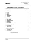
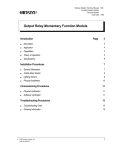
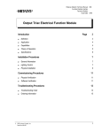
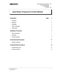
Metasys Network Technical Manual 636
Function Modules Section
Technical Bulletin
Issue Date 0793
Output Analog Isolated Function Module
Introduction
©
Page
3
•
Description
3
•
Application
4
•
Capabilities
4
•
Theory of Operation
5
•
Specifications
6
Installation Procedures
7
•
General Information
7
•
Physical Installation
7
•
Current Source (0 to 20 mA)
8
•
Voltage Source (0 to 10 volts)
9
•
Current Control (0 to 20 mA)
10
Commissioning Procedures
11
•
Physical Verification
11
•
Software Verification
11
Troubleshooting Procedures
13
•
Troubleshooting Chart
13
•
Ordering Information
15
1993 Johnson Controls, Inc.
Order No. 636-043
1
2 Function Modules—Output Analog Isolated Function Module
Introduction
The Output Analog Isolated (OAI) Function Module is an isolated
interface between the DCM and field devices. It is used whenever a
connected field device has an internal ground reference that would
interfere with the operation of an OAE Function Module. The OAI may
be configured to source isolated analog output voltage (0-10 VDC),
source isolated analog output current (0-20 mA), or modulate isolated
current (0-20 mA) for externally powered devices. The OAI Function
Module features:
●
●
●
digital to analog converter for converting DCM digital input into
isolated analog output
Auto/Manual (A-M) switch to enable/disable DCM control
manual set potentiometer for manual output control. (CW increases
output.)
●
optical isolation from DCM electronics
●
feedback indication of the Auto/Manual switch setting to the DCM
For non-isolated analog outputs, use the OAE Function Module.
The OAI Function Module plugs into any one of the bottom ten slots
associated with the DCM. Figure 1 shows typical function module
locations in the NCU. A five slot panel is pictured.
Output FMs
DCMs
A
M
oai101
O AI 101
Description
Figure 1: OAI Function Module Locations
Function Modules—Output Analog Isolated Function Module
3
Application
The OAI Function Module is typically used to:
●
●
Capabilities
control a variable speed motor controller
provide a current control (0 to 20 mA) for use with an external current
source
Table 1: Function Module Capabilities
Capability
Description
Purpose
Input from DCM
DCM inputs a digital command.
Allows DCM to provide automatic
control of outputs.
Auto/Manual Switch, and
Manual Adjustment
Switch selects one of:
- Auto—DCM control of outputs
Allows for manual override of
DCM control for special
situations.
- Manual—DCM control disabled
and output is controlled by
manual adjustment.
Allows for local/manual control,
even if the DCM is not present.
Power on Reset
At low power or after power up,
output goes to zero (in Auto
mode).
Provides controlled restart.
Output to Field
Module outputs an isolated
voltage or current signal
proportional to input signal.
Provides proportional control
signals for motor driven actuators
or variable speed controllers.
4 Function Modules—Output Analog Isolated Function Module
Theory of
Operation
OAI
Control
Electronics
and
Isolation
DCM
Signal
Conditioner
A uto
Manual
Manual
Adjustment
Current
Source,
Voltage
Source,
or
Current
Control
Field
Device
oai101
Figure 2: OAI Function Diagram
The process is:
●
●
●
●
●
The DCM provides a digital control signal.
The control electronics in the OAI latch the digital control signal, then
convert it to an isolated, proportional analog signal.
Depending on how the OAI is wired, this isolated analog signal is a
current source, voltage source, or will modulate externally sourced
current.
A manually controlled Auto/Manual switch can disable the DCM
control of the OAI outputs. The status of this switch is reported back
to the DCM.
With the Auto/Manual switch in the Manual position, the module
output is controlled by a manual adjustment on the OAI.
(CW increases the output.)
The unit will operate in the Manual mode without the DCM present. The
corresponding power supply must be present.
Function Modules—Output Analog Isolated Function Module
5
Specifications
Table 2: OAI Function Module Specifications
Specifications for Configurations
Current Source
Current Control
Category
Voltage Source
Product Code Number
FM-OAI101
Output Range
0 to 10 V
(25 mA maximum)
0 to 20 mA
Output Limits
40 mA (Maximum)
910 ohm maximum
load, including line
resistance
Output Protection
Fused at 500 mA with a non-field replaceable fuse
Output Isolation
350V minimum isolation between output and analog supplies; and output and
DCM electronics
Input-Output
Characteristics
Linear analog output proportional to digital input value
Input Range
0 to 1024, based on a 10 bit data value from the DCM
Response Time
1 sec. for a full range change
Resolution
0.1% of full range
Accuracy
±0.4% of full scale output at 70 ±2°F. (21 ± 1.1°C)
Thermal Effects
Gain Drift: ± 0.0055% per °F (±0.01% per °C) of full scale deviation
Offset Drift: ± 0.0055% per °F (±0.01% per °C) of full scale deviation
Calibration
The module is factory calibrated.
Default Condition
Output = 0 VDC on loss
of input power
Source Power
Power is from the PWR in the NCU/NEU.
Operating
Environmental
Requirements
32 to 122°F (0 to 50°C)
10 to 90% noncondensing relative humidity
86°F (30°C) maximum dew point
Storage/Shipping
Environmental
Requirements
-40 to 158°F (-40 to 70°C)
5 to 95% noncondensing relative humidity
86°F (30°C) maximum dew point
Size
0.85 in. H x 3.06 in. W x 7.0 in. L
(2.2 cm H x 7.8 cm W x 17.8 cm L)
Weight
0.5 lb. (0.22 kg)
Agency Compliance
FCC Part 15 Subpart J - Class A, UL 916, CSA C22.2 No. 205
Agency Listings
UL Listed and CSA Certified as part of Metasys®
6 Function Modules—Output Analog Isolated Function Module
Output = 0 mA on loss
of input power
0 to 20 mA
(4 VDC to 30 VDC)
(External power supply)
Output = 0 mA on loss
of input power
(External power)
Installation Procedures
General
Information
When installing and connecting function modules:
●
●
follow NEC and local codes
observe maximums as specified in the specification table and in these
installation guidelines
Physical
Installation
Assumptions
The following procedure for the physical installation of the OAI Function
Module assumes:
●
NCU/NEU panel is installed.
●
Connections to field devices are complete.
●
You have engineering drawings defining details for the installation.
●
Procedure
You are familiar with Metasys Network terminology, and the location
and operation of power switches.
For each OAI Function Module in the network, perform the following
steps.
1.
Set the Auto/Manual switch to Manual.
2.
Adjust output to minimum.
3.
Refer to the engineering drawings, and identify the proper panel and
slot number location for this module.
4.
Open the latch.
5.
Insert the module in the appropriate slot.
6.
Close the latch, locking function module in place.
Function Modules—Output Analog Isolated Function Module
7
Current Source
(0 to 20 mA)
Figure 3 diagrams the wiring for current source (0 to 20 mA) applications
using the OAI Function Module.
TBF
OAI
DCM
C o n tr o l
E le c tr o n ic s
and
Is o la tio n
1
Signal
Conditioner
A u to
M anu al
A d ju s tm e n t
2
5
Field
Device
O p tion a l*
2
TBF in left bay
of NCU/NEU
3
6
+
_
V a r ia b le
C u rr e n t
S o urc e
M anual
C o n n e c tio n to D C M
co m p le te d th r o u g h
in te rn a l co n n e cto r
o n e n d o f fu n ctio n
m o d u le .
2 5 0 ft. m a x .
No. 18 AW G
tw is te d p a ir
* O p tio n a l fo r O A I.
S h ie ld m a y b e r e q u ire d b y th e
fie ld d e vic e fo r n o is e im m u n ity .
S e e in d iv id u a l m a n u fa ctu r e r 's
sp e cific a tio n s h e e t.
TBF in right bay
of NCU/NEU
1
4
1
4
2
5
3
6
Strip wire and insert in side face of TBF. Use
set screw in front face to secure.
oaiwire
Figure 3: Wiring for Current Source Applications
8 Function Modules—Output Analog Isolated Function Module
Voltage Source
(0 to 10 volts)
Figure 4 diagrams the wiring for voltage source (0 to 10 volts)
applications using the OAI Function Module.
TBF
OAI
DCM
Control
Electronics
and
Isolation
4
Signal
Conditioner
A u to
Manual
Adjustment
F ie ld
D e v ic e
O p tion a l*
5
TBF in left bay
of NCU/NEU
3
6
+
_
V a r ia b le
C u rr e n t
S o urc e
M anual
C o n n e c tio n to D C M
co m p le te d th r o u g h
in te rn a l co n n e cto r
o n e n d o f fu n ctio n
m o d u le .
2 5 0 ft. m a x .
No. 18 AW G
tw is te d p a ir
2
5
* O p tio n a l fo r O A I.
S h ie ld m a y b e r e q u ire d b y th e
fie ld d e vic e fo r n o is e im m u n ity .
S e e in d iv id u a l m a n u fa ctu r e r 's
sp e cific a tio n s h e e t.
TBF in right bay
of NCU/NEU
1
4
1
4
2
5
3
6
Strip wire and insert in side face of TBF. Use
set screw in front face to secure.
oaiwire
Figure 4: Wiring for Voltage Source Applications
Function Modules—Output Analog Isolated Function Module
9
Current Control
(0 to 20 mA)
Figure 5 diagrams the wiring for current control (0 to 20 mA) applications
using the OAI Function Module.
TBF
OAI
DCM
Control
Electronics
and
Isolation
2
Signal
Conditioner
A u to
C u rr e n t
S ourc e
Manual
Adjustment
O p tion a l*
Externally
Powered
Field
Device
(4 to 30V)
3
TBF in left bay
of NCU/NEU
3
6
+
_
M anual
C o n n e c tio n to D C M
co m p le te d th r o u g h
in te rn a l co n n e cto r
o n e n d o f fu n ctio n
m o d u le .
2 5 0 ft. m a x .
No. 18 AW G
tw is te d p a ir
2
5
* O ptio n al fo r O A I.
S hield m a y be re qu ired b y th e
fie ld d e vice fo r no ise im m u nity .
S ee ind ividu al m a nu fa ctu re r's
spe cifica tion s he et.
TBF in right bay
of NCU/NEU
1
4
1
4
2
5
3
6
Strip wire and insert in side face of TBF. Use
set screw in front face to secure.
oaiwire
Figure 5: Wiring for Current Control Applications
10 Function Modules—Output Analog Isolated Function Module
Commissioning Procedures
Physical
Verification
Assumptions
Procedure
The following procedure for the physical verification of the OAI Function
Module assumes:
●
Physical installation at the NCU/NEU and PWR panel is complete.
●
Power is available at the panel power supply and at the field device.
For each OAI Function Module in the network, perform the following
steps.
1.
Power up the appropriate DCM power supply.
2.
Adjust the manual control on the function module and verify that the
intended device responds, and that the response is appropriate.
Software
Verification
Assumptions
The following procedure for the software verification of the OAI Function
Module assumes:
●
●
●
Procedure
Physical installation at the NCU/NEU panel is complete, including
NCM, DCM, FM, etc.
The operating software for the network has been downloaded to the
NCM controlling the panel.
An Operator Workstation is available.
For each OAI Function Module in the network, perform the following
steps.
1.
Select the System summary that includes this OAI object.
2.
Set Auto/Manual switch on the OAI to Auto.
3.
Use the software override command and verify that the object’s value
attribute (as seen in the Summary) matches the actual value for the
field device.
Function Modules—Output Analog Isolated Function Module
11
12 Function Modules—Output Analog Isolated Function Module
Troubleshooting Procedures
Troubleshooting
Chart
Use the diagram in Figure 6 (next page) as a troubleshooting guide. It
applies for failures between point objects and field devices connected
through an OAI Function Module.
Function Modules—Output Analog Isolated Function Module
13
Start
Is the
Summary
containing this object
displaying correct
values?
Yes
Exit
No
Is
Point
object definition
OK?
Fix definition.
See Operator Workstation
User's Manual .
No
Yes
Is DCM
error LED off and
is N2 polling and
responding?
No
Troubleshoot DCM.
See DCM 101 Technical
Bulletin .
Yes
No
Is
external power
required?
Yes
Is
external power
supply OK?
No
Yes
Using a
DVM, check FM
output. Is it
OK?
No
Repair or replace if
JCI is responsible.
Replace FM.
See Ordering Information
ordering information. Refer
to Material Return and
Allowance Program,
Procedure 3C2700
for
information on returning
defective FMs.
for
Yes
Using a
DVM, check input
to field device.
OK?
No
Troubleshoot
connections
and wiring.
Yes
Repair or replace field
device if JCI is responsible.
Figure 6: OAI Troubleshooting
14 Function Modules—Output Analog Isolated Function Module
oaiflow
Ordering
Information
Table 3: Code Number
Description
OAI Function Module
Product Code Number
FM-OAI101-0
Function Modules—Output Analog Isolated Function Module
15
Notes
Controls Group
507 E. Michigan Street
P.O. Box 423
Milwaukee, WI 53201
16 Function Modules—Output Analog Isolated Function Module
FAN 636
Metasys Network Technical Manual
Revision Date 0793
Printed in U.S.A.