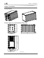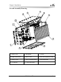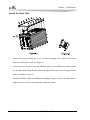
1
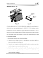
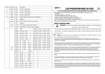
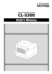
CPC-3406-ATR 3U CPCI 传导加固机箱 3U Rugged CPCI Chassis Version: B00 Copyright Notice Information offered in this manual is believed to be correct at the time of printing, and is subject to change without prior notice in order to improve reliability, design and function and does not represent a commitment on the part of the manufacturer. In no event will the manufacturer be liable for direct, indirect, special, incidental, or consequential damages arising out of improper installation and/or use, or inability to use the product or documentation. This user manual is protected by copyright. No part of this manual may be reproduced, stored in any retrieval system, or transmitted, in any form or by any means, mechanical, electronic, photocopied, recorded or otherwise, without the prior written permission from the manufacturer. Trademarks EVOC is a registered trademark of EVOC Intelligent Technology Co., Ltd. Other product names mentioned herein are used for identification purposes only and may be trademark and/or registered trademarks of their respective companies. Please visit our website: http://www.evoc.com for more information, or send an email to the Technical Support Mailbox [email protected] (International) or [email protected] (Domestic) for consultation. Customer Service Hotline: 4008809666 Safety Instructions 1. Please read this manual carefully before using the product; 2. Before inserting, removing or re-configuring motherboards or expansion cards, first disconnect the computer and peripherals from their power sources to prevent electric shock to human bodies or damage to the product; 3. Before moving the product, please unplug the AC cable from the power socket; 4. When inserting or removing boards, please firstly unplug the AC power cable; 5. Before connecting or disconnecting any signal cable, make sure all power cables are unplugged in advance; 6. After turning off the computer, wait at least 30 seconds before turning it back on; 7. All the operations such as upgrade, remove or installation shall be implemented on the ESD worktable, because some exactitude components are sensitive to electrostatic discharge (ESD). 8. If there's no ESD worktable, please take the following measures to prevent damage from electrostatic discharge (ESD): a) Wear a antistatic wrist strap and connect it with the metal part of the corresponding product; b) Always touch the metal enclosure or frame before touching any components; c) Keep part of your body in contact with the metal enclosure to discharge the static while handling components; d) Avoid unnecessary movement; e) Hold the components (especially the boards) by the edges; f) Place the components on a grounded, static-free operating platform. Use a conductive foam pad if available (not the component wrapper). g) 9. Do not let the components slide on the operating platform. Use cross-head screwdriver to operate. A magnetic screwdriver is recommended (Magnet helps to prevent screws from remaining in the enclosure). Do not leave any tools or accessories inside the enclosure; 10. Ensure abundant cooling and ventilation. 11. Non-professional personnel are not allowed to open the enclosure. C o n t e n t s Chapter 1 Product Introduction.....................................................................................1 Overview ......................................................................................................................1 Main Functions .............................................................................................................1 Mounting Mode ............................................................................................................3 Requirements of Transportation and Storage ................................................................3 Chapter 2 Installation....................................................................................................4 Product Outline.............................................................................................................4 Product Appearance and Installation Dimensions.........................................................4 Overall Assembly Drawing...........................................................................................5 Install the Hard Disk.....................................................................................................6 Install the Add-in Card..................................................................................................7 Chapter 1 Product Introduction Chapter 1 Product Introduction Overview CPC-3406-ATR is a 3U rugged CPCI computer system, borrowing the appearance and the dimensions of the GJB441-88 5/8 ATR. It can meet requirements of harsh environments, especially computational control and data acquisition in aviation, aerospace and armament. The product adopts high-intensity al-alloy to conduct and dissipate heat; therefore, it is excellent in air-proof, anti-vibration and EMC performance and can be applied in a wide temperature range of -40°C ~ 85°C. The system supports six 3U CPCI slots (one is the motherboard slot while the other five are expansion slots). The backplane and the I/O board are connected via CPCI connector. All of the I/O connectors are brought out via on-board aviation plugs without converter cable; therefore, the reliability of the system is improved. It can meet the military communication and computing requirements under different environment by using different patch boards or backplanes. Main Functions Power: 18V~36V DC wide voltage input; All of the I/O connectors are aviation plugs, which are stable and reliable; The I/O connectors include: one VGA, two COMs, two LANs, two USBs and one DC-in connector; One fool-proof power switch. Power Consumption of the PC Power Consumption: 58.08W (No program is operating within the system); Power Consumption: 65.76W (Operate 3D 03 v110); CPC-3406-ATR -1- Chapter 1 Product Introduction Mechanical Dimensions, Weight and Environment Dimensions: 352mm (L) x 157.2mm (W) x 194mm (H); Note: the dimensions excluding the handle: 315mm (L) x 157.2mm (W) x 194mm (H); Net Weight: 8.65Kg; Operating Environment: Temperature: -40°C ~85°C; Humidity: 5% ~ 90% (non-condensing); Storage Environment: Temperature: -45°C ~ 90°C; Humidity: 5% ~ 90% (non-condensing). EMC Radiation disturbance is compliant with GB9254-2008, class B; Conducted susceptibility meets the threshold of GB/T 17618-1998. Reliability MTBF≥50000h; MTTR≤0.5h. Safety Meets the basic requirements of GB4943. Mechanical and Environment Adaptability Anti-vibration: comply with ANSI/VITA 47 4.4.2, level 2; The V2-level connectors can endure the following vibration, each axis per hour: 1. 5Hz ~ 100Hz PSD, increasing by 3dB/octave; 2. 100Hz ~ 1000Hz PSD=0.04g2/Hz; -2- CPC-3406-ATR Chapter 1 Product Introduction 3. 1000Hz ~ 2000Hz PSD, decreasing by 6dB/octave; Anti-shock: comply with ANSI/VITA 47 4.5.1, OS1. The connectors can endure 20g, 11ms, half sine impulse or 20g, 11ms, final peak saw-tooth impulse in three axes. Mounting Mode □19″ Rack Mount □Wall Mount □Desktop □Embedded Panel □VESA Standard Supporting Arm □Portable ■Others: Cartridge Airborne Electronic Device Requirements of Transportation and Storage Transportation Well-packaged products are suited for transportation by truck, ship, and plane. During transportation, products should not be put in open cabin or carriage. When transshipping en route, products should not be stored in open air without protection from the atmospheric conditions. Products should not be transported together with inflammable, explosive and corrosive substances and are not allowed to be exposed to rain, snow and liquid substances and mechanical force. Storage Products should be stored in package box when it is not used. And warehouse temperature should be 0°C ~ 40°C, and relative humidity should be 20% ~ 85%. In the warehouse, there should be no harmful gas, inflammable, explosive products, and corrosive chemical products, and strong mechanical vibration, shock and strong magnetic field interference. The package box should be at least 10cm above ground, and 50cm away from wall, thermal source, window and air inlet. CPC-3406-ATR -3- Chapter 2 Installation Chapter 2 Installation Product Outline Product Appearance and Installation Dimensions Unit: mm -4- CPC-3406-ATR Chapter 2 Installation Overall Assembly Drawing 1. Front Cover 2. Backplane 3. Carrier 4. Right Side Board 5. Rear Cover 6. Slot for Expansion Card 7. Upper Cover 8. Slot for Motherboard 9. Partition Board 10. I/O Board 11. Left Side Board CPC-3406-ATR -5- Chapter 2 Installation Install the Hard Disk 1. Loosen the screws fixing the cover via inner hexagon screw driver and locate them at a safety place (refer to Figure-1); 2. Loosen the two screws fixing the HDD module via crosshead screwdriver, take out the hard disk fixing bracket and then tighten the four screws fixing the hard disk according to Figure-2; 3. Install the HDD module (assembled according to Figure-2) back into the chassis; tighten the cover after connecting and fixing the cables. -6- CPC-3406-ATR Chapter 2 Installation Install the Add-in Card All of the add-in cards for CPC-3406-ATR shall be configured by users themselves, which shall meet the signal definitions for PICMG 3U CPCI backplane and the mechanical and structural standard for rugged CPCI. It is recommended to use the locking device with excellent conductive and heat dissipation design and the handle with pull-assistant devices (refer to Figure-2). Please note that anti-static gloves shall be used during operation. 1. When removing the add-in card, please do as follows: 1) Loosen the screws fixing the cover via inner hexagon screw driver and locate them at a safe place (refer to Figure-1); 2) Loosen the two clamp bars on both sides of the board via screwdriver and make sure the clamp bars have returned to the loose status; 3) Hold the chassis with one hand and the handle of the board by the other hand; open outward and then pull the board outward with force until it breaks away from the backplane connector; CPC-3406-ATR -7- Chapter 2 Installation 4) Take out the board along the guide rail and locate it at a safety location. 2. When installing the add-in card, please do as follows: 1) Make sure the clamp bars of the board are loose; hold the board with one hand and then hold the handle of the board with the other hand tightly with the component side facing up; 2) Push the board into the corresponding slot along the guide rail; 3) When the board is approaching the backplane connector, hole the panel of the board with both hands and push the panel inward at the same time until the dowel pin of the board is completely inserted into the backplane slot; 4) After confirming the board is properly installed, tighten the clamp bars on both sides of the board via screwdriver; make sure the board is stable and the clamp bars and the guide slot are well connected; 5) Tighten the cover via screws. -8- CPC-3406-ATR