1
Logic Express 9
Instruments
Copyright © 2009 Apple Inc. All rights reserved.
Your rights to the software are governed by the
accompanying software license agreement. The owner or
authorized user of a valid copy of Logic Express software
may reproduce this publication for the purpose of learning
to use such software. No part of this publication may be
reproduced or transmitted for commercial purposes, such
as selling copies of this publication or for providing paid
for support services.
The Apple logo is a trademark of Apple Inc., registered in
the U.S. and other countries. Use of the “keyboard” Apple
logo (Shift-Option-K) for commercial purposes without
the prior written consent of Apple may constitute
trademark infringement and unfair competition in violation
of federal and state laws.
Every effort has been made to ensure that the information
in this manual is accurate. Apple is not responsible for
printing or clerical errors.
Note: Because Apple frequently releases new versions
and updates to its system software, applications, and
Internet sites, images shown in this manual may be slightly
different from what you see on your screen.
Apple
1 Infinite Loop
Cupertino, CA 95014
408-996-1010
www.apple.com
Apple, the Apple logo, GarageBand, Logic, Mac, and
Ultrabeat are trademarks of Apple Inc., registered in the
U.S. and other countries.
Finder is a trademark of Apple Inc.
Other company and product names mentioned herein
are trademarks of their respective companies. Mention of
third-party products is for informational purposes only
and constitutes neither an endorsement nor a
recommendation. Apple assumes no responsibility with
regard to the performance or use of these products.
Contents
Preface
9
9
10
10
An Introduction to the Logic Express Instruments
About the Logic Express Instruments
About the Logic Express Documentation
Additional Resources
Chapter 1
13
14
15
15
16
17
17
18
ES E
Getting to Know the ES E Interface
Using the ES E Oscillators
Using the ES E LFO
Using the ES E Filter
Using the ES E Envelope
Using the ES E Output Parameters
Extended ES E Parameters
Chapter 2
19
20
21
22
23
23
ES M
Getting to Know the ES M Interface
Using the ES M Oscillator
Using the ES M Filter and Filter Envelope
Using the ES M Level Envelope and Output Controls
Extended ES M Parameters
Chapter 3
25
26
27
27
28
29
30
30
ES P
Getting to Know the ES P Interface
Using the ES P Oscillators
Using the ES P LFO
Using the ES P Filter
Using the ES P Envelope and Level Controls
Using the Integrated ES P Effects
Extended ES P Parameters
Chapter 4
33
34
35
37
ES1
Getting to Know the ES1 Interface
Using the ES1 Oscillators
Using the ES1 Filter Parameters
3
38
39
41
44
45
4
Using the ES1 Amplifier Parameters
Using the ES1 Envelope Parameters
Modulating the Sound of the ES1
Adjusting Global ES1 Parameters
ES1 MIDI Controller List
Chapter 5
47
48
49
50
62
64
74
76
106
108
110
112
123
ES2
ES2 Architecture and Features
Getting to Know the ES2 interface
Using the ES2 Oscillators
Using the ES2’s Global Parameters
Using the ES2 Filters
Using the ES2 Amplifier Parameters
Working with Modulation in the ES2
Using the ES2’s Integrated Effect Processing Section
Creating Random ES2 Sound Variations
Using Macro Controls and Assigning Controllers in the ES2
ES2 Tutorial: Creating Sounds
ES2 Tutorial: Using Templates to Create Sounds
Chapter 6
131
132
133
136
137
138
139
139
EFM1
Getting to Know the EFM1 Interface
Working with the EFM1 Modulator and Carrier Parameters
Working with the EFM1 Modulation Parameters
Adjusting Global EFM1 Parameters
Setting EFM1 Output Parameters
Creating EFM1 Random Sound Variations
Assigning EFM1 MIDI Controllers
Chapter 7
141
141
144
145
147
148
153
156
157
158
160
163
EVOC 20 PolySynth
How the EVOC 20 Polysynth Works
Getting to Know the EVOC 20 PolySynth Interface
EVOC 20 PolySynth Sidechain Analysis Parameters
EVOC 20 PolySynth (U/V) Detection Parameters
EVOC 20 PolySynth Synthesis Section Parameters
EVOC 20 PolySynth Formant Filter Parameters
EVOC 20 PolySynth Modulation Parameters
EVOC 20 PolySynth Output Parameters
Getting the Best Results with the EVOC 20 PolySynth
A Brief Vocoder History
EVOC20 Block Diagram
Contents
Chapter 8
165 External Instrument
165 Getting to Know the External Instrument Interface
166 Using the External Instrument
Chapter 9
167
168
169
170
172
173
178
182
184
187
188
202
205
210
213
215
216
218
219
221
222
223
224
233
234
237
239
239
Chapter 10
241 Klopfgeist
242 Using the Klopfgeist Parameters
Chapter 11
243
244
246
247
247
251
EXS24 mkII
EXS24 mkII Features
Getting to Know the EXS24 mkII Interface
About EXS24 Sampler Instruments
Getting to Know the EXS24 mkII Parameter Window
Using the EXS24 mkII Sampler Instruments Pop-Up Menu
Adjusting EXS24 mkII Global Parameters
Using the EXS24 mkII Pitch Parameters
Working with EXS24 mkII Filter Parameters
EXS24 mkII Output Parameters
Working with EXS24 mkII Modulation
An Overview of the EXS24 mkII Instrument Editor
Creating EXS24 mkII Instruments, Zones, and Groups
Editing EXS24 mkII Zones and Groups
Setting EXS24 mkII Zone Parameters
Using the EXS24 mkII Zone Loop Parameters
Setting EXS24 mkII Group Parameters
Using the EXS24 mkII Advanced Group Selection Parameters
Graphical Editing of EXS24 mkII Zones and Groups
Saving, Renaming, and Exporting EXS24 mkII Instruments
Editing Samples in the EXS24 mkII Sample Editor
Using an External Instrument Editor with the EXS24 mkII
Importing EXS24 mkII Sampler Instruments
Managing EXS24 Sampler Instruments
Setting EXS24 mkII Sampler Preferences
Configuring EXS24 mkII Virtual Memory
Advanced EXS24 mkII RAM Management
Using the VSL Performance Tool in EXS24 mkII
Ultrabeat
Getting to Know the Structure of Ultrabeat
Loading and Saving Ultrabeat Settings
Getting to Know the Ultrabeat Interface
Getting to Know Ultrabeat’s Assignment Section
Importing Sounds and EXS Instruments into Ultrabeat
Contents
5
Chapter 12
6
254
256
257
258
262
267
268
269
270
272
273
279
289
299
303
304
305
305
310
316
316
317
318
318
Getting to Know the Ultrabeat Synthesizer Section
Getting to Know the Ultrabeat Oscillators
Getting to Know the Ultrabeat Oscillator Parameters
Using Oscillator 1 in Ultrabeat
Using Oscillator 2 in Ultrabeat
Using the Ultrabeat Ring Modulator
Using the Ultrabeat Noise Generator
Getting to Know the Ultrabeat Filter and Distortion Section
Using Ultrabeat’s Multimode Filter
Using Ultrabeat’s Distortion Circuit
Using the Ultrabeat Output Section
Working with Modulation in Ultrabeat
Working with the Ultrabeat Step Sequencer
Automating Parameter Values in Ultrabeat’s Step Sequencer
Exporting Ultrabeat Patterns as MIDI Regions
Using MIDI to Control Ultrabeat’s Sequencer
Ultrabeat Tutorial: Introduction
Ultrabeat Tutorial: Creating Kick Drums
Ultrabeat Tutorial: Creating Snare Drums
Ultrabeat Tutorial: Creating Toms and Tonal Percussion
Ultrabeat Tutorial: Creating Hi-Hats and Cymbals
Ultrabeat Tutorial: Creating Metallic Sounds
Ultrabeat Tutorial: Creating Extreme Sounds
Ultrabeat Tutorial: Programming in Building Blocks
321
322
323
324
325
326
328
329
330
331
332
333
334
335
335
336
337
338
GarageBand Instruments
GarageBand Instrument Features
GarageBand Analog Basic
GarageBand Analog Mono
GarageBand Analog Pad
GarageBand Analog Swirl
GarageBand Analog Sync
GarageBand Bass
GarageBand Church Organ
GarageBand Digital Basic
GarageBand Digital Mono
GarageBand Digital Stepper
GarageBand Drum Kits
GarageBand Electric Clav(inet)
GarageBand Electric Piano
GarageBand Guitar
GarageBand Horns
GarageBand Hybrid Basic
Contents
Appendix
340
342
343
344
345
346
347
348
GarageBand Hybrid Morph
GarageBand Piano
GarageBand Sound Effects
GarageBand Strings
GarageBand Tonewheel Organ
GarageBand Tuned Percussion
GarageBand Voice
GarageBand Woodwind
349
349
353
355
369
373
Synthesizer Basics
Sound Basics
What Is a Synthesizer?
How Subtractive Synthesizers Work
Other Synthesis Methods
A Brief History of the Synthesizer
Contents
7
Preface
An Introduction to the
Logic Express Instruments
Logic Express provides a number of software-based instruments that include: innovative
synthesizers, a powerful sampler, and authentic recreations of vintage instruments. You
can use these instruments for real time playback in Logic Express.
The Logic Express instruments cover almost every sound generation need you will
encounter in your day to day work with Logic Express. All instruments feature intuitive
interfaces that provide access to all functions and parameters. Pristine audio quality is
assured when needed, or—at the other end of the spectrum—extremely harsh and dirty
sounds can be created with many of the included instruments. All instruments are highly
optimized for efficient CPU usage, maximizing the real time playback potential of your
computer.
This preface covers the following:
• About the Logic Express Instruments (p. 9)
• About the Logic Express Documentation (p. 10)
• Additional Resources (p. 10)
About the Logic Express Instruments
Logic Express includes a comprehensive collection of instruments that can be used in
your music projects. Instruments are grouped in the following categories.
Instrument category
Included instruments
Synthesizer
•
•
•
•
•
•
•
Drum synthesizer
• Ultrabeat
Software sampler
• EXS24 mkII
Vocoder synthesizer
• EVOC 20 PolySynth
EFM1
ES E
ES M
ES P
ES1
ES2
Klopfgeist
9
Instrument category
Included instruments
Utility
• External Instrument
GarageBand instruments
Analog Basic, Analog Mono, Analog Pad, Analog Swirl, Analog Sync,
Bass, Digital Basic, Digital Mono, Digital Stepper, Drum Kits, Electric
Clavinet, Electric Piano, Guitar, Horns, Hybrid Basic, Hybrid Morph,
Piano, Sound Effects, Strings, Tonewheel Organ, Tuned Percussion,
Voice, Woodwind (see GarageBand Instruments)
About the Logic Express Documentation
Logic Express comes with various documents that will help you get started as well as
provide detailed information about the included applications.
• Logic Express User Manual: This onscreen manual provides comprehensive instructions
for using Logic to set up a recording system, compose music, edit audio and MIDI files,
and output audio for CD productions.
• Exploring Logic Express: This booklet provides a fast-paced introduction to the main
features and tasks in Logic Express, encouraging hands-on exploration for new users.
• Logic Express Control Surfaces Support: This onscreen manual describes the configuration
and use of control surfaces with Logic Express.
• Logic Express Instruments: This onscreen manual provides comprehensive instructions
for using the powerful collection of instruments included with Logic Express.
• Logic Express Effects: This onscreen manual provides comprehensive instructions for
using the powerful collection of effects included with Logic Express.
• Logic Express Working with Apogee Hardware: This onscreen manual describes the use
of Apogee hardware with Logic Express.
Additional Resources
Along with the documentation that comes with Logic Express, there are a variety of other
resources you can use to find out more.
Release Notes and New Features Documents
Each application offers detailed documentation that covers new or changed features and
functions. This documentation can be accessed in the following location:
• Click the Release Notes and New Features links in the application Help menu.
Logic Express Website
For general information and updates, as well as the latest news on Logic Express, go to:
• http://www.apple.com/logicexpress
10
Preface
An Introduction to the Logic Express Instruments
Apple Service and Support Websites
For software updates and answers to the most frequently asked questions for all Apple
products, go to the general Apple Support webpage. You’ll also have access to product
specifications, reference documentation, and Apple and third-party product technical
articles.
• http://www.apple.com/support
For software updates, documentation, discussion forums, and answers to the most
frequently asked questions for Logic Express, go to:
• http://www.apple.com/support/logicexpress
For discussion forums for all Apple products from around the world, where you can search
for an answer, post your question, or answer other users’ questions, go to:
• http://discussions.apple.com
Preface
An Introduction to the Logic Express Instruments
11
ES E
1
The 8-voice ES E (ES Ensemble) synthesizer is ideal for quickly creating warm, rich pad
and ensemble sounds.
ES E produces sounds using subtractive synthesis. It features an oscillator that generates
harmonically rich waveforms. You subtract (cut, or filter out) portions of these waveforms,
and reshape them, to create new sounds.
If you’re totally new to synthesizers, it might be best to start off with Synthesizer Basics,
which will introduce you to the terminology and give you a great overview of different
synthesis methods and how they work.
This chapter covers the following:
• Getting to Know the ES E Interface (p. 14)
• Using the ES E Oscillators (p. 15)
• Using the ES E LFO (p. 15)
• Using the ES E Filter (p. 16)
• Using the ES E Envelope (p. 17)
• Using the ES E Output Parameters (p. 17)
• Extended ES E Parameters (p. 18)
13
Getting to Know the ES E Interface
Before you take a look at the individual parameters of the ES E, this section will familiarize
you with the various elements in the ES E graphical interface.
Oscillator parameters
Filter parameters
LFO parameters
Output parameters
Envelope parameters
Oscillator parameters
• Oscillator parameters: The oscillator Wave and Octave parameters are shown in the
area to the left. The oscillator generates the waveforms that form the basis of your
sound. See Using the ES E Oscillators.
• LFO parameters: The LFO parameters (below the oscillator Wave parameter knob) are
used to modulate the sound. See Using the ES E LFO.
• Filter parameters: The section to the right of the Oscillator parameters includes the
Cutoff (Frequency) and Resonance knobs. You use the filter to contour the waveforms
sent from the oscillator. See Using the ES E Filter.
• Envelope parameters: The area to the right of the Filter parameters contains the Envelope
parameters, which control the level of the sound over time. See Using the ES E Envelope.
• Output parameters: The area at the extreme right houses the Volume knob, responsible
for the main output level, and the Effect parameters. The effects can be used to color
or thicken the sound. See Using the ES E Output Parameters.
• Extended parameters: Not shown in the image, the extended parameters are accessed
by clicking the triangle at the lower left of the interface. These parameters include bend
and tuning functions. See Extended ES E Parameters.
14
Chapter 1 ES E
Using the ES E Oscillators
The synthesizer oscillator generates a waveform, which is then sent to other portions of
the synthesizer engine for processing or manipulation.
• Wave knob: Selects the waveform of the oscillator, which is responsible for the basic
color of the tone. The leftmost setting of the Wave parameter causes the oscillators to
output sawtooth signals. Across the remaining range, the oscillators output pulse waves,
with the average pulse width being defined by the Wave parameter position.
• 4, 8, 16 buttons: Allow you to switch the pitch in octaves (transpose it up or down). The
lowest setting is 16 feet, and the highest is 4 feet. The use of the term feet to determine
octaves comes from the measurements of organ pipe lengths. The longer (and wider)
the pipe, the deeper the tone.
Using the ES E LFO
The LFO (low frequency oscillator) generates a cyclic waveform that is used to modulate
the ES E waveform. The behavior and effect of the LFO depend on whether a sawtooth
or pulse wave is selected.
• If Wave is set to sawtooth, the LFO modulates the frequency of the waveform, resulting
in a vibrato or siren effect—depending on the LFO speed and intensity.
• If Wave is set to a pulse wave, the LFO modulates the waveform’s pulse width (PWM).
• Vib/PWM knob: Defines the intensity of the LFO modulation.
• Speed knob: Sets the frequency of the LFO modulation.
Chapter 1 ES E
15
Note: When the pulse width becomes very narrow, the signal sounds as if it is being
interrupted (“breaking up”). Given this potential artifact, set the PWM intensity with
care, and select the Wave parameter’s 12 o’clock position (50% rectangular) for the
pulse width, if you want to achieve the maximum modulation range.
Using the ES E Filter
The ES E includes a lowpass filter that lets you contour the output from the oscillator.
• Cutoff knob: Controls the cutoff frequency of the ES E filter.
• Resonance knob: Boosts or cuts portions of the signal that surround the frequency
defined by the Cutoff parameter.
Note: Increasing the Resonance value results in a rejection of bass (low frequency
energy) when using lowpass filters.
• AR Int knob: The ES E features one simple envelope generator per voice-offering an
Attack and a Release parameter (see Using the ES E Envelope). The AR Int knob defines
the amount (depth) of cutoff frequency modulation applied by the envelope generator.
• Velo Filter knob: Sets the velocity sensitivity of the cutoff frequency modulation applied
by the envelope generator.
Note: This parameter has no effect if AR Int is set to 0.
16
Chapter 1 ES E
Using the ES E Envelope
The AR (Attack and Release) envelope affects both the filter cutoff (AR Int) and the level
of the sound over time.
• Attack slider: Determines the time that it takes for the signal to reach the initial, desired
signal level (the sustain level).
• Release slider: Determines the time that it takes for the signal to fall from the sustain
level to a level of zero.
Using the ES E Output Parameters
The ES E output stage consists of the Volume section and the Chorus/Ensemble buttons.
• Volume knob: Sets the overall output level of the ES E.
• Velo Volume knob: Sets the amount (depth) of velocity sensitivity to incoming MIDI
note events. When it is set to higher values, each note is louder, if struck more firmly.
At lower values, the dynamic response is reduced, so that there is little difference when
you play a note pianissimo (soft) or forte (loud/hard).
Chapter 1 ES E
17
• Chorus I, Chorus II, and Ensemble buttons: Click to switch any of these effect variations
on or off.
• Chorus I and Chorus II are typical chorus effects.
• Chorus II is characterized by a stronger modulation.
• The Ensemble effect employs a more complex modulation routing, creating a fuller
and richer sound.
• If none of the buttons is active, the effects processor is turned off.
Extended ES E Parameters
The ES E offers three additional parameters that are accessed by clicking the disclosure
triangle at the lower left of the interface.
• Pos. Bender Range: Changes the positive (upwards) pitch bend range in semitone steps.
This allows you to use the pitch bend controller of your keyboard to bend the ES E
pitch.
• Neg. Bender Range: The default Neg. Bender Range value is Pos PB (Positive Pitch Bend).
In essence, this means that only positive pitch bend is available. You can adjust the
negative (downwards) pitch bend range in semitone steps-up to 2 octaves (a value of
24).
• Tune: Tunes the entire instrument in cents. A cent is 1/100th of a semitone.
18
Chapter 1 ES E
ES M
2
The monophonic ES M (ES Mono) synthesizer is a good starting point if you’re looking
for bass sounds that punch through your mix.
ES-M features an automatic fingered portamento mode, making bass slides easy. It also
provides an automatic filter compensation circuit that delivers rich, creamy basses, even
when using higher resonance values.
ES M produces sounds using subtractive synthesis. It features an oscillator that generates
harmonically rich waveforms. You subtract (cut, or filter out) portions of these waveforms,
and reshape them, to create new sounds.
If you’re totally new to synthesizers, it might be best to start off with Synthesizer Basics,
which will introduce you to the terminology and give you a great overview of different
synthesis methods and how they work.
This chapter covers the following:
• Getting to Know the ES M Interface (p. 20)
• Using the ES M Oscillator (p. 21)
• Using the ES M Filter and Filter Envelope (p. 22)
• Using the ES M Level Envelope and Output Controls (p. 23)
• Extended ES M Parameters (p. 23)
19
Getting to Know the ES M Interface
Before you take a look at the individual parameters of the ES M, this section will familiarize
you with the various elements in the ES M graphical interface.
Filter and Filter Envelope
parameters
Overdrive
Oscillator parameters
Output parameters
• Oscillator parameters: The oscillator Mix and Octave parameters are shown in the area
to the left. The oscillator generates the basic waveforms that form the basis of your
sound. See Using the ES M Oscillator.
• Filter and Filter Envelope parameters: The section to the right of the Oscillator parameters
includes the (Cutoff ) Frequency and Resonance knobs. The filter is used to contour the
waveforms sent from the oscillators. The Filter Envelope parameters are found towards
the upper right. These control the filter cutoff over time. See Using the ES M Filter and
Filter Envelope.
• Output parameters: The angle-shaped area to the lower right contains the Level Envelope
and Output parameters, which control the level of the sound over time. The Overdrive
knob is located near the right edge of the interface, halfway up. The Overdrive can be
used to color or add bite to the sound. See Using the ES M Level Envelope and Output
Controls.
• Extended parameters: Not shown in the image, the extended parameters are accessed
by clicking the triangle at the lower left of the interface. These parameters include bend
and tuning functions. See Extended ES M Parameters.
20
Chapter 2 ES M
Using the ES M Oscillator
The synthesizer oscillator is used to generate a waveform, which is then sent to other
portions of the synthesizer engine for processing or manipulation.
• Mix knob: Sets the waveform of the oscillator, which is responsible for the basic color
of the tone.
• Setting the Wave parameter all the way to the left causes the oscillators to output
sawtooth signals.
• Setting the Wave parameter all the way to the right outputs a 50% rectangular
wave—which is heard one octave below the sawtooth.
• For any Wave setting between these extreme positions, the oscillator outputs a
crossfaded mix of the two waveforms.
• 8, 16, 32 buttons: Allow you to switch the pitch in octaves (transpose it up or down).
The lowest setting is 32 feet, and the highest is 8 feet. The use of the term feet to
determine octaves comes from the measurements of organ pipe lengths. The longer
(and wider) the pipe, the deeper the tone.
• Glide knob: Determines the speed of the glide (the time it takes to slide between note
pitches). At a value of 0, no glide effect occurs.
Note: The ES M always works in a fingered portamento mode, with notes played in a
legato style resulting in a glide (portamento) from pitch to pitch.
Chapter 2 ES M
21
Using the ES M Filter and Filter Envelope
The ES M includes a lowpass filter that lets you contour the output from the oscillator.
The filter features a dedicated envelope.
Filter Envelope
parameters
• Cutoff knob: Controls the cutoff frequency of the ES M filter. Its slope is 24 dB/octave.
• Resonance knob: Boosts or cuts portions of the signal that surround the frequency
defined by the Cutoff parameter.
Note: Increasing the Resonance value results in a rejection of bass (low frequency
energy) when using lowpass filters. The ES M compensates for this side-effect internally,
resulting in a more bassy sound.
• Int knob: Defines the amount (the intensity or depth) of cutoff frequency modulation
applied by the envelope generator.
• Decay knob: Defines the decay time of the filter envelope.
• Velo knob: Sets the velocity sensitivity of the cutoff frequency modulation applied by
the envelope generator.
Note: The Decay and Velo parameters have no effect if Int is set to 0.
22
Chapter 2 ES M
Using the ES M Level Envelope and Output Controls
The output stage of the ES M offers the following parameters.
Level parameters
• Decay knob: Sets the decay time of the dynamic stage. The attack, release, and sustain
times of the synthesizer are internally set to 0.
• Velo knob: Determines the velocity sensitivity of the dynamic stage.
• Vol knob: Sets the master output level of the ES M.
• Overdrive knob: Controls the level of the integrated overdrive effect.
Important: To avoid hurting your ears or damaging your speakers, consider turning
down the Volume level before setting Overdrive to a high value; then turn it up
gradually.
Extended ES M Parameters
The ES M offers three additional parameters that are accessed by clicking the disclosure
triangle at the lower left of the interface.
• Pos. Bender Range: Changes the positive (upwards) pitch bend range in semitone steps.
This allows you to use the pitch bend controller of your keyboard to bend the ES P
pitch.
• Neg. Bender Range: The default Neg. Bender Range value is Pos PB (Positive Pitch Bend).
In essence, this means that only positive pitch bend is available. You can adjust the
negative (downwards) pitch bend range in semitone steps-up to 2 octaves (a value of
24).
• Tune: Tunes the entire instrument in cents. A cent is 1/100th of a semitone.
Chapter 2 ES M
23
ES P
3
The 8-voice ES P (ES Poly) emulates classic polyphonic synthesizers of the 1980s.
It is a versatile instrument that is capable of producing a huge variety of useful musical
sounds. The creation of classic analog synthesizer brass sounds is just one of its many
strengths.
ES P produces sounds using subtractive synthesis. It features an oscillator that generates
harmonically rich waveforms. You subtract (cut, or filter out) portions of these waveforms,
and reshape them, to create new sounds.
If you’re totally new to synthesizers, it might be best to start off with Synthesizer Basics,
which will introduce you to the terminology and give you a great overview of different
synthesis methods and how they work.
This chapter covers the following:
• Getting to Know the ES P Interface (p. 26)
• Using the ES P Oscillators (p. 27)
• Using the ES P LFO (p. 27)
• Using the ES P Filter (p. 28)
• Using the ES P Envelope and Level Controls (p. 29)
• Using the Integrated ES P Effects (p. 30)
• Extended ES P Parameters (p. 30)
25
Getting to Know the ES P Interface
Before you take a look at the individual parameters of the ES P, this section will familiarize
you with the various elements in the ES P graphical interface.
Oscillator parameters
Filter parameters
Effect parameters
Envelope parameters
LFO parameters
Level parameters
• Oscillator parameters: The Oscillator sliders are shown in the area to the left. The Octave
parameters are also found in this section. The oscillators generate the basic waveforms
that form the basis of your sound. See Using the ES P Oscillators.
• LFO parameters: The LFO parameters (to the right of the Oscillator parameters) are used
to modulate the sound. See Using the ES P LFO.
• Filter parameters: The vertical column in the center includes the (Cutoff ) Frequency and
Resonance knobs and the Key Follow buttons. The filter is used to contour the
waveforms sent from the oscillators. See Using the ES P LFO.
• Envelope and Level parameters: The area to the right of the Filter parameters contains
the Envelope and Level parameters, which control the level of the sound over time.
See Using the ES P Envelope and Level Controls.
• Effect parameters: The area at the extreme right contains the Chorus and Overdrive
parameters. These can be used to color or thicken the sound. See Using the Integrated
ES P Effects.
• Extended parameters: Not shown in the image, the extended parameters are accessed
by clicking the triangle at the lower left of the interface. These parameters include bend
and tuning functions. See Extended ES P Parameters.
26
Chapter 3 ES P
Using the ES P Oscillators
The ES P features several oscillators that output different waveforms. These signals can
be mixed together—at different levels—providing countless variations of the raw material
used for your sounds.
• Oscillator sliders: Set the level of the waveforms output by the oscillators.
• In addition to triangular, sawtooth, and rectangular waves, the rectangular waves of
two sub-oscillators are also available. The left sub-oscillator fader is one octave lower
than the main oscillators, and the right sub-oscillator fader is two octaves lower. Use
these to fatten up the sound.
• The pulse width of all rectangular waves is fixed at 50%.
• The rightmost fader adds white noise to the mix. This is the raw material for classic
synthesizer sound effects, such as ocean waves, wind, and helicopters.
• 4, 8, 16 buttons: Allow you to switch the pitch in octaves (transpose it up or down). The
lowest setting is 16 feet, and the highest is 4 feet. The use of the term feet to determine
octaves comes from the measurements of organ pipe lengths. The longer (and wider)
the pipe, the deeper the tone.
Using the ES P LFO
The ES P features an LFO (low frequency oscillator), which can do either of the following:
• Modulate the frequency of the oscillators, resulting in a vibrato.
Chapter 3 ES P
27
• Modulate the cutoff frequency of the dynamic lowpass filter, resulting in a wah wah
effect.
• Vib/Wah knob: Turn to the left to set a vibrato; turn to the right to cyclically modulate
the filter.
• Speed knob: Sets the rate of the vibrato or cutoff frequency modulation.
Using the ES P Filter
The ES P includes a lowpass filter that lets you contour the output from the oscillator.
• Frequency knob: Controls the cutoff frequency of the ES P’s lowpass filter.
• Resonance knob: Boosts/cuts portions of the signal that surround the frequency defined
by the Frequency knob.
28
Chapter 3 ES P
Note: Increasing the Resonance value results in a rejection of bass (low frequency
energy) when using lowpass filters. The ES P compensates for this side-effect internally,
resulting in a more bassy sound.
• 1/3, 2/3, 3/3 (Key Follow) buttons: The cutoff frequency can be modulated by MIDI note
number (keyboard position); you may know this parameter as keyboard follow on other
synthesizers. Enable one of the 1/3, 2/3, 3/3 buttons to choose one-third, two-thirds,
or full-keyboard follow. If no button is active, the key you strike won’t affect the cutoff
frequency. This makes the lower notes sound relatively brighter than the higher ones.
If 3/3 is chosen, the filter follows the pitch, resulting in a constant relationship between
cutoff frequency and pitch. This is typical of many acoustic instruments where higher
notes sound both brighter in tone and higher in pitch.
• ADSR Int knob: Defines the amount (depth) of cutoff frequency modulation applied by
the envelope generator (see Using the ES P Envelope and Level Controls).
• Velo Filter knob: Sets the velocity sensitivity of the cutoff frequency modulation applied
by the envelope generator. The main envelope generator (ADSR) modulates the cutoff
frequency over the duration of a note. The intensity of this modulation can respond to
velocity information. If you play pianissimo (velocity = 1), the modulation is minimal.
If you strike with the hardest fortissimo (velocity = 127), the modulation is more intense.
Using the ES P Envelope and Level Controls
The ES P features an ADSR envelope that affects both the filter cutoff (ADSR Int) and the
level of the sound over time. This section also covers the master level control parameters.
• Attack slider: Determines the time it takes for the signal to reach the initial, desired
signal level (the sustain level).
• Decay slider: Determines the time it takes for the signal to fall from the attack level to
the sustain level.
Chapter 3 ES P
29
• Sustain slider: Determines the desired signal level (the sustain level).
• Release slider: Determines the time it takes for the signal to fall from the sustain level
to a level of zero.
• Volume knob: Sets the overall output level of the ES P.
• Velo Volume knob: Sets the amount (depth) of velocity sensitivity to incoming MIDI
note events. When set to higher values, each note is louder if struck more firmly. At
lower values, the dynamic response is reduced, so that there is little difference when
you play a note pianissimo (soft) or forte (loud/hard).
Using the Integrated ES P Effects
The ES P offers integrated stereo chorus and overdrive effects. These are based on similar
effects processors found in the affordable Japanese synthesizers of the 1980s—which
the ES P, itself, emulates.
• Chorus knob: Sets the intensity (depth) of the integrated chorus effect.
• Overdrive knob: Determines the overdrive/distortion level of the ES P output.
Important: To avoid hurting your ears or damaging your speakers, consider turning
down the Volume level before setting Overdrive to a high value; then turn it up
gradually.
Extended ES P Parameters
The ES P offers three additional parameters that are accessed by clicking the disclosure
triangle at the lower left of the interface.
• Pos. Bender Range: Changes the positive (upwards) pitch bend range in semitone steps.
This allows you to use the pitch bend controller of your keyboard to bend the ES P
pitch.
30
Chapter 3 ES P
• Neg. Bender Range: The default Neg. Bender Range value is Pos PB (Positive Pitch Bend).
In essence, this means that only positive pitch bend is available. You can adjust the
negative (downwards) pitch bend range in semitone steps-up to 2 octaves (a value of
24).
• Tune field: Tunes the entire instrument in cents. A cent is 1/100th of a semitone.
Chapter 3 ES P
31
ES1
4
The ES1 emulates the circuits of analog synthesizers in a simple, streamlined interface.
ES1 produces sounds using subtractive synthesis. It features an oscillator and sub-oscillator
that generate harmonically rich waveforms. You subtract (cut, or filter out) portions of
these waveforms and reshape them to create new sounds. The ES1’s tone-generation
system also provides flexible modulation options that make it easy to create punchy
basses, atmospheric pads, biting leads, and sharp percussion.
If you’re totally new to synthesizers, it might be best to start off with Synthesizer Basics,
which will introduce you to the terminology and give you a great overview of different
synthesis systems and how they work.
This chapter covers the following:
• Getting to Know the ES1 Interface (p. 34)
• Using the ES1 Oscillators (p. 35)
• Using the ES1 Filter Parameters (p. 37)
• Using the ES1 Amplifier Parameters (p. 38)
• Using the ES1 Envelope Parameters (p. 39)
• Modulating the Sound of the ES1 (p. 41)
• Adjusting Global ES1 Parameters (p. 44)
• ES1 MIDI Controller List (p. 45)
33
Getting to Know the ES1 Interface
Before you take a look at the individual parameters of the ES1, this section will familiarize
your with the various elements that constitute the ES1’s graphical interface, which is
broken down into six main areas.
Oscillator parameters
Filter parameters
Amplifier parameters
Modulation parameters
Envelope parameters
Global parameters
• Oscillator parameters: Shown to the left, the oscillators generate the basic waveforms
that form the basis of your sound. See Using the ES1 Oscillators. A number of related
parameters that directly influence the overall sound, such as Tune, are found in the
Global Parameters section of the interface. See Adjusting Global ES1 Parameters.
• Filter parameters: These include the circular Filter area, and Drive and Key scaling
parameters. You use the filter to contour the waveforms sent from the oscillators. See
Using the ES1 Filter Parameters.
• Amplifier parameters: The area to the right contains the Amplifier parameters. See Using
the ES1 Amplifier Parameters.
• Envelope parameters: The ADSR sliders in the lower-right corner of the ES1 can be used
to control both filter cutoff and the amplifier level over time. See Using the ES1 Envelope
Parameters.
• Modulation parameters: The dark green/gray area houses the modulation sources,
modulation router, modulation envelope, and amplitude envelope, which you can use
to modulate the sound in a number of ways. See Modulating the Sound of the ES1.
• Global parameters: Global sound control parameters are located on the bottom
green/gray strip. This is where you can assign and adjust global tuning, activate the
in-built chorus, and more. The chorus can be used to color or thicken the sound. See
Adjusting Global ES1 Parameters.
34
Chapter 4 ES1
Using the ES1 Oscillators
The ES1 features a primary oscillator and a sub-oscillator. The primary oscillator generates
a waveform, which is then sent to other parts of the synthesizer for processing or
manipulation. The sub-oscillator generates a secondary waveform one or two octaves
below that of the primary oscillator.
• Wave knob: Selects the waveform of the primary oscillator, which is responsible for the
basic color of the tone. See Setting ES1 Oscillator Waveforms.
• Mix slider: Defines the level relationship between the primary and sub-oscillator signals.
When the sub-oscillator is switched off, its output is completely removed from the
signal path.
• Sub knob: The sub-oscillator generates square, pulse, and white-noise waveforms. It
also allows you to route a side chain signal through the ES1 synthesizer engine (see
Using the ES1 Sub-Oscillator).
• 2, 4, 8, 16, 32 buttons: Transpose the pitch of the oscillators up or down by octaves. The
lowest setting is 32 feet, and the highest is 2 feet. The use of the term feet to determine
octaves comes from the measurements of organ pipe lengths. The longer and wider
the pipe, the deeper the tone (for a description of the global Tune parameters, see
Adjusting Global ES1 Parameters).
Setting ES1 Oscillator Waveforms
The following table outlines how the oscillator waveform affects your synthesizer sound.
Waveform
Basic tone
Comments
Sawtooth
Warm and even
Useful for strings, pads, bass, and
brass sounds
Triangle
Sweet sounding, softer than
sawtooth
Useful for flutes, pads
Square
Hollow and “woody” sounding
Useful for basses, clarinets, and
oboes
Chapter 4 ES1
35
Waveform
Basic tone
Comments
Pulse
“Nasal” sounding
Great for reed instruments, synth
blips, basses
Using Pulse Width Modulation in the ES1
You can freely set any pulse width in-between the square wave and pulse wave symbols
of the Wave knob. The pulse width can also be automatically modulated in the modulation
section (see Using the ES1 Router). Modulating the pulse width with a slowly cycling LFO,
for example, allows periodically mutating, fat bass sounds.
Using the ES1 Sub-Oscillator
The sub-oscillator provides the following waveform options:
• A square wave that plays one or two octaves below the frequency of the primary
oscillator.
• A pulse wave that plays two octaves below the frequency of the primary oscillator.
• Variations of these waveforms with different mixes and phase relationships. Their use
results in different sounds.
• White noise which is useful for creating percussion sounds, as well as wind, surf, and
rain sounds.
• You can also completely disable the sub-oscillator by choosing OFF.
Processing Side Chain Signals Through the ES1
The sub-oscillator of the ES1 allows you to run an external channel strip signal through
the ES1 synthesizer engine, by using a side chain.
To process a channel strip signal through the ES1 synthesizer engine
1 Set the Sub knob to EXT.
2 Choose the side chain source channel strip from the Side Chain menu at the top of the
plug-in window.
36
Chapter 4 ES1
Using the ES1 Filter Parameters
This section outlines the filter parameters of the ES1.
• Cutoff slider: Controls the cutoff frequency of the ES1’s lowpass filter.
• Resonance slider: Cuts or boosts the portions of the signal that surround the frequency
defined by the Cutoff parameter. Boost can be set so intensively that the filter begins
to oscillate by itself (see Driving the ES1 Filter to Self-Oscillation).
Tip: You can simultaneously adjust the cutoff frequency and resonance parameters by
dragging vertically (cutoff) or horizontally (resonance) on the word Filter, found between
the Slope buttons.
• Slope buttons: The lowpass filter offers four different slopes of band rejection above
the cutoff frequency. The four settings are arranged clockwise from the top left, as
follows:
• 24 dB classic: Mimics the behavior of a Moog filter. Turning up the resonance results
in a reduction of the low end of the signal.
• 24 dB fat: Compensates for the reduction of low frequency content caused by high
Resonance values. This resembles the behavior of an Oberheim filter.
• 12 dB: Provides a soft, smooth sound which is reminiscent of the early Oberheim
SEM.
• 18 dB: Tends to resemble the filter sound of Roland’s TB-303.
• Drive slider: An input level control, which allows you to overdrive the filter. Use it to
change the behavior of the Resonance parameter, which will eventually distort the
sound of the waveform.
• Key slider: Controls how strongly the keyboard pitch (the note number) modulates the
filter’s cutoff frequency:
• If Key is set to zero, the cutoff frequency won’t change, no matter which key you
strike. This makes the lower notes sound relatively brighter than the higher ones.
Chapter 4 ES1
37
• If Key is set to maximum, the filter follows the pitch, resulting in a constant relationship
between cutoff frequency and pitch. This mirrors the properties of many acoustic
instruments where higher notes sound both brighter in tone and higher in pitch.
• ADSR via Vel slider: Determines how note velocity affects the filter cutoff frequency
modulation—caused by the envelope generator (see Using the ES1 Envelope
Parameters).
Driving the ES1 Filter to Self-Oscillation
You can make the ES1 filter output a sine wave by following the steps below. This will
allow you to “play” the filter-generated sine wave with the keyboard.
To output a sine wave from the filter
1 Switch the Sub knob to OFF.
2 Move the Mix slider to the very bottom (Sub).
3 Turn the Resonance knob to the maximum position.
Using the ES1 Amplifier Parameters
The parameters in the ES1 Amplifier section allow you to fine-tune the behavior of your
sound’s level. These are separate from the global Out Level parameter, found on the strip
at the bottom of the interface, and which acts as the ES 1’s master volume (see Adjusting
Global ES1 Parameters).
• Level via Vel slider: Determines how note velocity affects the synthesizer level-set by
the global Out Level parameter. The slider’s upper arrow indicates the level when you
play fortissimo. The lower arrow indicates the level when you play pianissimo
(velocity = 1). The greater the distance between the arrows (indicated by the blue bar),
the more the volume is affected by incoming velocity messages. You can simultaneously
adjust the modulation range and intensity by dragging the blue bar-between the
arrows-and moving both arrows at once.
38
Chapter 4 ES1
• Amplifier Envelope Selector buttons: The AGateR, ADSR, and GateR buttons define which
of the ADSR envelope generator controls have an effect on the amplifier envelope (see
Using the Envelope to Control the ES1 Amplifier).
Using the ES1 Envelope Parameters
The ES1 features an attack, decay, sustain, and release (ADSR) envelope that can shape
the filter cutoff and the level of the sound over time.
• Attack slider: Determines the amount of time that it takes for the envelope to reach
the initial, desired level.
• Decay slider: Determines how long it takes for the envelope to fall to the sustain level,
following the initial attack time.
• Sustain slider: Sets the sustain level, which is held until the keyboard key is released.
• Release slider: Determines the length of time that it takes the envelope to fall from the
sustain level to a level of zero.
Using the Envelope to Control ES1 Cutoff Frequency
The envelope generator modulates the filter cutoff frequency over the duration of a note.
The intensity of this modulation—and how it responds to velocity information—is set
by the ADSR via Vel slider arrows (in the Filter Parameters section).
ADSR via Vel slider
Chapter 4 ES1
39
The modulation range is determined by the two arrows. The minimum amount of
modulation is indicated by the lower arrow. The upper arrow indicates the maximum
amount of modulation. The blue bar between the arrows shows the dynamic range of
this modulation. You can simultaneously adjust the modulation range and intensity by
dragging the blue bar and moving both arrows at once.
Tip: If you’re unfamiliar with these parameters, set the Cutoff to a low value, Resonance
to a high value, and move both of the ADSR via Vel arrows upwards. Constantly strike a
note on the keyboard while changing the arrows to discover how these parameters work.
Using the Envelope to Control the ES1 Amplifier
The AGateR, ADSR, and GateR buttons (in the Amplifier Parameter section) define which
of the ADSR envelope generator controls affect the amplifier envelope. All ADSR
parameters remain active for the filter.
Amplifier Envelope
Selector buttons
The letters A, D, S, and R refer to the attack, decay, sustain, and release phases of the
envelope (see Using the ES1 Envelope Parameters). Gate refers to a control signal used
in analog synthesizers that tells an envelope generator that a key is pressed. As long as
an analog synthesizer’s key is pressed, the gate signal maintains a constant voltage. When
Gate is used as a modulation source in the voltage-controlled amplifier (instead of the
envelope itself ), it creates an organ type envelope without any attack, decay, or release-an
even, sustained sound.
In the ES1, the Amplifier Envelope selector buttons have the following effect on played
notes:
• AGateR: The Attack and Release sliders of the ADSR Envelope control the attack and
release phases of the sound. In-between these phases, the Gate control signal is used
to maintain a constant level, while the note is held. As soon as you release the key, the
release phase begins. The Decay and Sustain sliders of the ADSR Envelope have no
impact on the sound’s level.
• ADSR: This is the standard operating mode of most synthesizers, where the level of the
sound over time is completely controlled by the ADSR Envelope.
40
Chapter 4 ES1
• GateR: The Gate control signal is used to maintain a constant level, while the note is
held. As soon as you release the key, the release phase begins. The Attack, Decay and
Sustain sliders of the ADSR Envelope have no impact on the sound’s level.
Modulating the Sound of the ES1
The ES1 offers a number of simple, yet flexible, modulation routing options. Modulation
is used to add animation to your sound over time, making it more interesting, lively, or
realistic. A good example of this type of sonic animation is the vibrato used by orchestral
string players.
LFO parameters
Router
Modulation Envelope
• LFO parameters: Used to modulate other ES1 parameters. See Using the ES1 LFO.
• Router: Allows you to choose which ES1 parameters are modulated. See Using the ES1
Router below.
• Modulation Envelope: A dedicated modulation control source, it can directly control
other ES1 parameters, or it can control the LFO level. See Using the ES1 Mod Envelope.
Using the ES1 Router
The router is used to determine which of the ES1 parameters are modulated by the LFO
(see Using the ES1 LFO) and/or by the Modulation Envelope (see Using the ES1 Mod
Envelope). The parameter target buttons in the left column enable LFO modulation, and
the ones in the right column set the target for the Modulation Envelope.
Parameter target buttons
• Pitch buttons: Turn on to modulate the pitch—the frequency—of the oscillators.
• Pulse Width buttons: Turn on to modulate the pulse width of the pulse wave.
Chapter 4 ES1
41
• Mix buttons: Turn on to modulate the mix between the primary and sub-oscillators.
• Cutoff buttons: Turn on to modulate the cutoff frequency of the filter.
• Resonance buttons: Turn on to modulate the resonance of the filter.
• Volume buttons: Turn on to modulate the main volume.
• Filter FM button (modulation envelope only): Turn on to use the triangle wave of the
oscillator to modulate the filter cutoff frequency. This modulation can result in a
pseudo-distortion of the sound, or it can create metallic, FM-style sounds. The latter
occurs when the only signal you can hear is the self-oscillation of the resonating filter
(see Driving the ES1 Filter to Self-Oscillation).
• LFO Amp (modulation envelope only): Turn on to modulate the overall amount of LFO
modulation.
Using the ES1 LFO
The LFO (low frequency oscillator) generates an adjustable, cyclic waveform that can be
used to modulate other ES1 parameters (as discussed in Using the ES1 Router).
• Wave knob: Sets the LFO waveform. You can choose from triangle, ascending and
descending sawtooth, square wave, sample & hold (random), and a lagged, smoothly
changing random wave. Each of these waveforms cycles in its own way, providing
different types of modulation. You can also assign a side chain signal as a modulation
source (EXT). Choose the side chain source channel strip from the Side Chain menu at
the top of the plug-in window.
• Rate slider and field: Defines the speed—the frequency—of the LFO waveform cycles.
• If you set values to the left of zero, the LFO phase is locked to the tempo of the host
application—with phase lengths adjustable between 1/96 bar and 32 bars. If you
select values to the right of zero, the LFO phase runs freely.
• When set to zero, the LFO outputs at a constant and full level, which allows you to
manually control the LFO speed with your keyboard’s modulation wheel. This could
be useful, for example, if you wanted to change the pulse width by moving your
keyboard’s modulation wheel. The pulse width would be chosen as the LFO
modulation target (left router column), and the modulation intensity range would
be determined by the Int via Whl setting.
42
Chapter 4 ES1
• Int via Whl slider: The upper arrow defines the intensity of the LFO modulation if the
modulation wheel (MIDI controller 1) is set to its maximum value. The lower arrow
defines the amount of LFO modulation if the modulation wheel is set to zero. The
distance between the arrows—shown by a green bar—indicates the range of your
keyboard’s modulation wheel. You can simultaneously adjust the modulation range
and intensity by dragging the green bar, thus moving both arrows at once. Note that
as you do so, the arrows retain their relative distance from each other.
Using the ES1 Mod Envelope
The modulation envelope allows you to set a percussive type of decay envelope by
choosing low values, or attack type envelopes with high values.
• Form slider and field: Allows you to fade in (attack) or fade out (decay) the modulation.
When set to the full position, the modulation envelope is turned off.
• Int via Vel slider: The top arrow controls the upper modulation intensity setting for the
modulation envelope—if you strike a key with the hardest fortissimo (velocity = 127).
The bottom arrow controls the lower modulation intensity setting for the modulation
envelope—if you strike a key with the softest pianissimo (velocity = 1). The green bar
between the arrows displays the impact of velocity sensitivity on the intensity of the
modulation envelope. You can simultaneously adjust the modulation range and intensity
by dragging the green bar, thus moving both arrows at once. Note that as you do so,
the arrows retain their relative distance from each other.
Controlling ES1 Parameters and the LFO with the Mod Envelope
The Modulation Envelope can directly modulate the parameter chosen in the router. It
essentially determines the time it takes for the modulation to fade in or fade out. At its
center position, which can be accessed by clicking the middle mark, the modulation
intensity is static—no fade in or fade out will occur. When set to its full value, it delivers
a constant level.
To modulate a parameter with velocity
1 Select a modulation destination (Pulse Width, for example).
2 Set Form to full, and adjust the Int via Vel parameter as needed.
This results in a velocity-sensitive modulation of the oscillator pulse width.
More interestingly, the Modulation Envelope can directly control the LFO level when you
click the LFO Amplitude button in the right column of the router.
Chapter 4 ES1
43
µ
µ
To fade the LFO modulation in or out
Choose a positive Form value (towards attack) to fade in the LFO modulation. The higher
the value, the longer it takes for you to hear the modulation.
Choose a negative value (towards decay) to fade out the LFO modulation. The lower the
value (closer to full), the shorter the fade out time is.
LFO control with envelopes is most often used for delayed vibrato, which is a technique
many instrumentalists and singers employ to intonate longer notes.
To set up a delayed vibrato
1 Position the Form parameter toward the right (attack).
2 Choose Pitch as the LFO target (left column).
3 Choose the triangular wave as the LFO waveform.
4 Select an LFO Rate of about 5 Hz.
5 Set the upper Int via Wheel arrow to a low value, and the lower arrow to 0.
Adjusting Global ES1 Parameters
This section covers global parameters that affect the overall sound, or behavior, of the
ES1. The global parameters are found in the strip that spans the lower edge of the ES1
interface. The Glide slider is displayed above the left end of the strip.
• Glide slider: Defines the amount of time it takes to slide between the pitches of each
triggered note. The Glide trigger behavior depends on the value chosen for the Voices
parameter (see below).
• Tune field: Tunes the entire instrument in cents. A cent is 1/100th of a semitone.
• Analog field: Slightly alters the pitch of each note, and the cutoff frequency, in a random
fashion. This emulates the random oscillator detuning and filter fluctuations that can
occur in polyphonic analog synthesizers—due to heat and age.
• Voices field: Sets the maximum number of notes that can be played simultaneously.
Each ES1 instance offers a maximum of 16 voices. Fewer played voices require less CPU
power.
• Bender Range field: Changes the sensitivity of the pitch bender. Adjustments are in
semitone steps.
• Neg Bender Range slider (Extended Parameters area): Adjusts the negative (downwards)
pitch bend range in semitone steps. The default value is Pos PB (Positive Pitch Bend),
which essentially means that there is no downward pitch bend available. Click the small
triangle at the lower left of the ES1 interface to access the Extended parameters area.
44
Chapter 4 ES1
• Chorus field: The ES1 offers two classic stereo chorus effects and one ensemble effect.
• Off deactivates the in-built chorus circuit.
• C1 and C2 are typical chorus effects. C2 is a variation of C1 and is characterized by a
stronger modulation.
• Ens (Ensemble) employs a more complex modulation routing, creating a fuller and
richer sound.
• Out Level field: Controls the master volume of the ES1.
Using the ES1 Analog Parameter
When the Analog parameter is set to a value of zero, the oscillator cycle start points of
all triggered voices are synchronized. This may be useful for percussive sounds, when
you want to achieve a sharper attack characteristic.
Use of Analog values higher than zero allows the oscillators of all triggered voices to cycle
freely. Use higher values if you’re aiming for a warm, analog type of sound—where subtle
sonic variations occur for each triggered voice.
Using the Voices Parameter in the ES1
When the Voices parameter is set to Legato, the ES1 behaves like a monophonic
synthesizer—with single trigger and fingered portamento engaged. This means that if
you play legato, a portamento will occur (the portamento time is defined by the Glide
slider). If you release each key before pressing a new one, the envelope will not be
triggered by the new note, and there will be no portamento.
Tip: You can use this feature to create pitch bend effects—without touching the pitch
bender—so make sure you select a higher Glide value when using the Legato setting.
ES1 MIDI Controller List
The ES1 responds to the following MIDI continuous controller numbers (CC).
Controller number
Parameter name
12
Oscillator pitch buttons
13
Oscillator waveform
14
Mix slider
15
Waveform of sub-oscillator
16
Drive slider
17
Cutoff slider
18
Resonance slider
19
Slope buttons
20
ADSR via Vel:lower slider
Chapter 4 ES1
45
46
Controller number
Parameter name
21
ADSR via Vel:upper slider
22
Attack slider
23
Decay slider
24
Sustain slider
25
Release slider
26
Key slider
27
Amplifier Envelope Selector buttons
28
Level via Velocity:lower slider
29
Level via Velocity:upper slider
30
Chorus parameter
31
Modulation envelope target
102
Modulation Envelope form slider
103
Modulation envelope:Int via Vel parameter:lower slider
104
Modulation envelope:Int via Vel parameter:upper slider
105
LFO rate
106
LFO waveform
107
LFO modulation target
108
LFO:Int via Whl:lower slider
109
LFO:Int via Whl:upper slider
110
Glide slider
111
Tune parameter
112
Analog parameter
113
Bender Range parameter
114
Out Level parameter
115
Voices parameter
Chapter 4 ES1
ES2
5
The ES2 synthesizer combines a powerful tone generation system with extensive
modulation features. It seamlessly blends subtractive synthesis and elements of FM and
wavetable synthesis methods to generate an extraordinary variety of sounds. This makes
it the perfect choice for creating powerful pads, evolving textures, rich basses, or synthetic
brass.
If you’re totally new to synthesizers, it might be best to start off with Synthesizer Basics,
which will introduce you to the fundamentals and terminology of different synthesis
systems.
This chapter covers the following:
• ES2 Architecture and Features (p. 48)
• Getting to Know the ES2 interface (p. 49)
• Using the ES2 Oscillators (p. 50)
• Using the ES2’s Global Parameters (p. 62)
• Using the ES2 Filters (p. 64)
• Using the ES2 Amplifier Parameters (p. 74)
• Working with Modulation in the ES2 (p. 76)
• Using the ES2’s Integrated Effect Processing Section (p. 106)
• Creating Random ES2 Sound Variations (p. 108)
• Using Macro Controls and Assigning Controllers in the ES2 (p. 110)
• ES2 Tutorial: Creating Sounds (p. 112)
• ES2 Tutorial: Using Templates to Create Sounds (p. 123)
47
ES2 Architecture and Features
The three oscillators of the ES2 provide classic analog synthesizer waveforms (including
noise) and 100 single-cycle waveforms, known as Digiwaves. This raw material forms the
basis for sounds that range from fat analog to harsh digital sounds, or hybrids of the two.
You can also cross-modulate oscillators, making it easy to create FM-style sounds. Further
options include the ability to synchronize and ring-modulate the oscillators, or to mix a
sine wave directly into the output stage, to thicken the sound.
ES2 features a flexible modulation router that offers up to ten simultaneous (user-defined)
modulation routings. These can be used alongside a number of hard-wired routings.
Further modulation options include the unique Planar Pad—which provides control of
two parameters on a two-dimensional grid. The Planar Pad itself can be controlled by the
sophisticated Vector Envelope. This is a multipoint, loop-capable envelope that makes it
easy to create complex, evolving sounds.
Lastly, Distortion, Chorus, Phaser, and Flanger effects are built into the ES2.
If you’d like to begin experimenting straight away, there are a number of settings that
can be loaded which will help you to get started. These are accompanied by two tutorial
sections which provide tips and information, and invite you to explore the ES2. See ES2
Tutorial: Creating Sounds and ES2 Tutorial: Using Templates to Create Sounds.
Note: Within the parameter description sections, you will often find information about
the use of parameters as modulation targets or sources. This underlines one of the ES2’s
greatest strengths—namely, the vast modulation possibilities it offers. It is recommended
that you read through the chapter, and return to these “modulation information” sections
(see below) when, and if, you need to refer to them. Descriptions on the use of all
modulation and control options, including reference tables, are covered in Working with
Modulation in the ES2.
48
Chapter 5 ES2
Getting to Know the ES2 interface
Before you take a look at the individual parameters and functions of the ES2, this section
will familiarize you with the various elements of the ES2’s graphical interface, which is
broken down into the following main areas.
Modulation router
Oscillator section
Global parameters
Global parameters
Effect section
Planar Pad
Amplifier parameters
Random parameters
Click here to display the
Vector Envelope.
Filter section
Macro Sound
parameters
Modulation controls and
parameters
• Oscillator section: The oscillator parameters are shown at the upper left of the
ES2 interface. The Triangle is used to set the mix relationships between the three
oscillators. See Using the ES2 Oscillators.
• Global parameters: A number of related global parameters that directly influence the
overall output of the ES2—such as Tune—are found to the left of the oscillators, and
above the amplifier and filter parameters. See Using the ES2’s Global Parameters.
• Filter section: The circular Filter area, including the Drive and Filter FM parameters. See
Using the ES2 Filters.
• Amplifier parameters: The area at the top right contains the output parameters, where
you can set the overall volume of the ES2, and add a sine signal at the output stage.
See Using the ES2 Amplifier Parameters.
Chapter 5 ES2
49
• Modulation router or Vector Envelope: The dark strip across the center of the ES2 interface
is shared by the modulation router and the Vector Envelope. You can use the buttons
at the right end of this section to switch between the two.
• The router links modulation sources, such as the envelopes and other parameters
shown in the lower portion of the interface, to modulation targets, such as the
oscillators and filters. See Getting to Know the ES2’s Modulation Router.
• The Vector Envelope is an extremely flexible and powerful envelope generator, which
provides extensive control over your sound. See Getting to Know the ES2’s Vector
Envelope.
• Modulation controls and parameters: The area immediately below the router is where
you can assign and adjust the modulation generator parameters (such as LFO and
envelope parameters). See Working with Modulation in the ES2.
• Planar Pad: The square area at the top right is a two-dimensional controller known as
the Planar Pad—which facilitates the simultaneous manipulation of two, freely
assignable, parameters. The Planar Pad can be controlled using the mouse, another
controller, or the Vector Envelope. See Using the ES2’s Planar Pad.
• Effect section: The built-in effect processing options are found to the right of the Output
parameters. See Using the ES2’s Integrated Effect Processing Section.
• Random parameters: Used to randomize sound parameters, the Random parameters
are found below the circular Filter area. See Creating Random ES2 Sound Variations.
• Macro and MIDI controller parameters: The area located on the thin, gray strip at the
bottom can display either Macro parameters or MIDI controller assignments. The
preassigned macro sound parameters are perfect for quick tweaks to the ES2’s sound
(and that of ES2-based GarageBand instruments). You can reassign MIDI control numbers
for these parameters if desired. See Using the ES2 Macro Control Parameters.
Using the ES2 Oscillators
The synthesizer oscillators are used to generate one or more waveforms. This signal is
then sent to other portions of the synthesizer engine for shaping, processing, or
manipulation.
Before the parameters are discussed, a few of the special features available to you in the
ES2 oscillator section should be mentioned.
• Oscillators 2 and 3 are almost identical to each other, but they differ from Oscillator 1.
• Oscillator 1 can be frequency modulated by Oscillator 2, for FM synthesis sounds.
• Oscillators 2 and 3 can be synchronized to, or ring modulated with, Oscillator 1. They
also have rectangular waves with either user-defined fixed-pulse widths or pulse width
modulation (PWM) features.
50
Chapter 5 ES2
• You can use the modulation router to simultaneously change the pulse widths of the
rectangular waves of Oscillator 1 and the synchronized and ring-modulated rectangular
waves of Oscillators 2 and 3.
Getting to Know the ES2 Oscillators
The following section gives you an overview of the parameters available for each oscillator.
You can find the oscillators in the area at the top left of the ES2 interface.
(Coarse) Frequency knob
Oscillator on/off button
Oscillator Mix (Triangle)
Wave knob
(Fine) Frequency
value field
• Oscillator on/off buttons: Click the oscillator number to the right of each oscillator to
activate or deactivate each oscillator independently. A green numeric button indicates
an active oscillator. A gray numeric button denotes an inactive oscillator. Deactivating
an oscillator saves computer processing power as you are not merely muting it—you
are actually turning it off.
• Wave knobs: Sets the type of waveform that an oscillator generates. The waveform is
responsible for the basic tonal color. See Using the ES2’s Basic Oscillator Waveforms.
• (Coarse) Frequency knobs: Sets the oscillator’s pitch—in semitone steps, over a range
of ±3 octaves. As an octave consists of 12 semitones, the ±12, 24, and 36 settings
represent octaves.
• (Fine) Frequency value field: Used to fine-tune the oscillator frequency (pitch). The value
display works as follows: the left numbers show the semitone setting, the right numbers
show the cent (1 cent = 1/100th semitone) setting. These are denoted by an s or c to
the right of the value. You can adjust these two values independently. For example,
an oscillator with the value 12 s 30 c sounds an octave (12 semitones) and 30 cents
higher than an oscillator with the value 0 s 0 c.
Chapter 5 ES2
51
• Oscillator Mix (Triangle): Dragging the square icon in the Triangle cross-fades (sets the
level relationships) between the three oscillators. See Setting the Oscillator Level Balance
in the ES2.
Using the ES2’s Basic Oscillator Waveforms
All of the ES2 oscillators output a number of standard waveforms—sine, pulse, rectangular,
sawtooth, and triangular waves—or, alternately, any of 100 Digiwaves (see Using Digiwaves
in the ES2). The following table includes the basic waveforms:
Waveform
Basic tone
Comments
Pulse/Rectangular
Nasal sounding
Great for reed instruments, synth blips, and basses
Square
Hollow and woody
sounding
Useful for basses, clarinets, and oboes. The pulse
width of (Oscillator 2 and 3) square waveforms can
be smoothly scaled between 50% and the thinnest
of pulses.
Sawtooth
Warm and even
Useful for strings, pads, bass, and brass sounds
Triangle
Sweet sounding, softer
than sawtooth
Useful for flutes and pad sounds.
Sine
A pure tone
The sine wave of Oscillator 1 can be frequency
modulated by Oscillator 2. This kind of modulation
forms the basis of FM synthesis (see Using
Frequency Modulation in the ES2).
Oscillators 2 and 3 also offer the selection of:
• A rectangular wave, synchronized to Oscillator 1.
• A sawtooth wave, synchronized to Oscillator 1.
• A ring modulator, which is fed by the output of Oscillator 1 and a square wave from
Oscillator 2.
• Colored noise for Oscillator 3 (see Using Noise in the ES2 (Oscillator 3 Only)).
Oscillator synchronization and ring modulation enable the creation of very complex and
flexible harmonic spectra. The principles behind oscillator synchronization are described
in Synchronizing the ES2 Oscillators. Ring modulation principles are discussed in Using
Ring Modulation in the ES2.
Using Pulse Width Modulation in the ES2
You can alter the tonal color of rectangular waveforms by scaling the width of waveform
pulses to any value. This is known as pulse width modulation.
52
Chapter 5 ES2
The pulse width modulation features of the ES2 are extensive. As an example, if rectangular
waves are chosen for all oscillators, you can simultaneously modulate the pulse width of
Oscillator 1 and the synchronized pulse waves of Oscillator 2 (or the square wave of
Oscillator 2’s ring modulator) and Oscillator 3.
µ
To set a basic pulse width in Oscillator 2 or 3
Drag the waveform rotary control in the area highlighted in the image above.
Only Oscillators 2 and 3 allow you to define a “base” pulse width, prior to any pulse width
modulation.
To set up a pulse width modulation routing (of Oscillator 1) in the router:
1 Choose Osc1Wave as the Target.
2 Choose LFO1 as the Source.
3 Adjust the modulation amount slider (a value of 0.12 is subtle, but sweet).
4 Choose a sine wave for LFO 1.
5 Adjust the LFO 1 Rate (0.160 Hz is nice for slow sweeps).
Chapter 5 ES2
53
Modulating ES2 Oscillator Pulse Width with an LFO
Pulse width modulation (PWM) can be automatically controlled with appropriate settings
in the router. A pulse wave (with PWM controlled by an LFO set to a sine wave) makes
a single oscillator sound vivid, undulating, and overtone-rich. Sonically, this is similar to
the sound of two slightly detuned, phasing oscillators, which is great for sustained bass
and pad sounds.
The graphic below shows a pulse wave, with the pulse width modulated by an LFO.
You can clearly see how the width of the pulses changes over time.
Note: Select the intensity and speed of the modulation with care, because the overall
volume decreases, and slight detuning occurs, when the pulses become very narrow
(below a width value of 10%).
Tip: Pulse width modulations via velocity-sensitive envelope generators sound very
dynamic—a great effect that is especially suitable for percussive bass sounds.
Using Frequency Modulation in the ES2
The principle of frequency modulation (FM) synthesis was developed in the late 1960s
and early 1970s by John Chowning. It was popularized by Yamaha’s range of
DX synthesizers in the 1980s. The ES2 can’t be compared with the DX series in the discipline
of pure FM synthesis, but it can certainly achieve some of the signature sounds of these
instruments.
How Frequency Modulation Works
Stated simply, the frequency of one signal generator, or oscillator, is
altered—modulated—by another signal generator. Positive values from the second
generator increase the frequency of the first generator. Negative values decrease the
frequency.
In a synthesizer, this type of modulation takes place in the audible range. Depending on
the design of the instrument, you can hear the signals of either the first oscillator alone
(being modulated by the other oscillator), or both oscillators. The interaction between
the two generators alters the waveform signal of the first oscillator and introduces a
number of new harmonics. This harmonic spectrum can then be used as the source signal
for further sound processing, such as filtering, envelope control, and so on. See Frequency
Modulation (FM) Synthesis for further information.
54
Chapter 5 ES2
How Frequency Modulation Works in the ES2
In the ES2, the frequency of Oscillator 1 (with a sine wave chosen—11 o’clock position
for the Wave knob) can be modulated by the output signal of Oscillator 2.
• When Oscillator 2 outputs a positive signal, the frequency of Oscillator 1 increases.
• When Oscillator 2 outputs a negative signal, the frequency of Oscillator 1 decreases.
The net effect of speeding up or slowing down the frequency of Oscillator 1 in each
waveform cycle is a distortion of the basic wave shape. This waveform distortion also has
the side benefit of introducing a number of new, audible harmonics.
Important: The impact of any frequency modulations you perform depends on both the
frequency ratio and the modulation intensity of the two oscillators.
To set the frequency ratio and adjust the modulation intensity
1 Adjust the Frequency (coarse and fine tune) parameter values of one, or both, oscillators.
2 Click (or drag) in the control range between the Sine and FM icons around the Oscillator 1
Wave knob. This determines the amount, or intensity, of frequency modulation.
FM Synthesis Options in the ES2 Router
You can also adjust the FM intensity by choosing the Osc1Wave modulation target in
the router.
• Use lower FM intensity values if you are after a subtle FM effect.
• If you’re after more extreme FM modulations, choose the Osc1WaveB target in the
router. See ES2 Modulation Target Reference for further details.
Using Different ES2 Waveforms for FM Synthesis
The “pure” FM synthesis method uses a sine wave for both the first and second signal
generator (both Oscillator 1 and 2 would be limited to generating a sine wave in the ES2
if you stuck with this approach).
The ES2, however, provides 100 Digiwaves and countless combinations of modulation
intensities and frequency ratios that can be used for either oscillator. This provides a vast
pool of harmonic spectra and tonal colors for you to experiment with—so it would be a
shame if you don’t take advantage of these options!
Chapter 5 ES2
55
Tip: The type of modulation that occurs can vary significantly when different waveforms
are chosen for Oscillator 2—the modulating oscillator—in particular.
Using Ring Modulation in the ES2
Ring modulation is a powerful tool for the creation of inharmonic, metallic, bell-like
sounds. The spectra resulting from its use are inharmonic at almost every frequency ratio.
The ring modulator is a device that dates back to the early days of the synthesizer.
How a Ring Modulator Works
A ring modulator has two inputs. At the output you hear both the sum and difference
frequencies of the input signals. If you ring modulate a sine oscillation of 200 Hz with a
sine oscillation of 500 Hz, the output signal of the ring modulator will consist of a 700 Hz
(sum) and a 300 Hz (difference) signal. Negative frequencies result in a change to the
phase polarity of output signals.
How Ring Modulation Works in the ES2
You can set Oscillator 2 to output a ring modulator signal by choosing the Ring setting
with the Oscillator 2 Wave knob. Feel free to experiment with different Frequency (main
and fine tune) values for one, or both, oscillators.
The Oscillator 2 ring modulator is fed with the output signal of Oscillator 1 and a square
wave—generated by Oscillator 2 itself. The pulse width of this square wave can be
modulated (see Using Pulse Width Modulation in the ES2).
Tip: Use sawtooth and rectangular (pulse width modulated) input signals from Oscillators
1 and 2, respectively, to create a much more complex output signal. The use of these
harmonically rich waveforms results in a number of extra sidebands becoming audible.
Using Digiwaves in the ES2
In addition to the basic synthesizer waveforms, all of the ES2 oscillators provide 100
additional waveforms, called Digiwaves. These are very short samples of the attack
transients of various sounds and instruments.
56
Chapter 5 ES2
µ
µ
µ
µ
To choose a Digiwave
Set the Wave knob to Sine (6 o’clock position), then do one of the following:
Control-click or right-click the Sine label, and choose a waveform from the pop-up menu.
Click-hold the Sine label and drag the mouse vertically.
Shift-click the menu, and type in a value, to select the Digiwave numerically.
ES2 Digiwave Modulation Options
The number assigned to each Digiwave is a parameter that can be modulated. This
feature allows the ES2 to produce sounds reminiscent of classic wavetable synthesizers
from PPG and Waldorf. See Wavetable, Vector, and Linear Arithmetic (LA) Synthesis.
You can automatically scroll through the list of Digiwaves by modulating the OscWave
target in the modulation router. If you choose a sufficiently low modulation intensity
and speed, you will hear each individual Digiwave being cross-faded.
The Digiwaves of the three oscillators can be modulated independently or as a group.
These modulation targets are discussed in Getting to Know the ES2 Oscillators.
Using Noise in the ES2 (Oscillator 3 Only)
The sonic palette of Oscillator 3 is bolstered by the inclusion of a noise generator, which
can be activated by choosing the noise waveform. By default, Oscillator 3’s noise generator
generates white noise.
White noise is defined as a signal that consists of all frequencies (an infinite number)
sounding simultaneously, at the same intensity, in a given frequency band. The width of
the frequency band is measured in Hertz. Sonically, white noise falls between the sound
of the consonant “F” and breaking waves (surf ). White noise is useful for synthesizing
wind and seashore noises, or electronic snare drum sounds.
Chapter 5 ES2
57
Modulating the Noise Color
Oscillator 3 has more up its sleeve than the output of neutral sounding white noise,
however. You can modulate the tonal color of the noise signal in real time—without
using the main filters of the ES2—by modulating the waveform of Oscillator 3.
To change the noise color, set up a modulation routing as follows: modulation target
Osc3Wave, source ModWhl. The modulation amount slider behaves somewhat differently
with this routing, essentially acting like a filter.
• Use negative modulation amount values (not −1.000) to set a descending filter slope
that roughly equates to 6 dB/octave, and the sound becomes darker (red noise) as
you adjust the mod wheel downwards.
• You can effectively tune this pseudofilter down to 18 Hz, with a modulation amount
setting of −1.000. When Osc3Wave is modulated positively, the noise becomes brighter
(blue noise).
• If you choose a modulation amount value of +1.000 for the Osc3Wave modulation
target, the filter cutoff frequency is set to 18 kHz.
Emulating Detuned Analog Synthesizer Oscillators in the ES2
The Analog parameter is found towards the top left of the ES2 interface. It alters the pitch
of each note—and the filter cutoff frequency—in a random fashion.
Much like polyphonic analog synthesizers, all three oscillators maintain their specific
frequency deviation from each other, but the pitches of all three oscillators are randomly
detuned by the same Analog amount. For example, if the Analog detuning is set to around
20%, all three oscillators (if used) will randomly drift by 20%.
• Low Analog values can add a subtle richness to the sound.
• Medium Analog values simulate the tuning instabilities of analog synthesizer circuitry,
which can be useful in achieving that much sought-after “warmth” of analog hardware
synthesizers.
• High Analog values result in significant pitch instability, which can sound truly out of
tune—but this may be perfect for your needs.
58
Chapter 5 ES2
Note: If the ES2 is set to Mono or Legato keyboard mode, the Analog parameter is effective
only when Unison is active. In this situation, Analog sets the amount of detuning between
the stacked (unison) voices. If the Voices parameter is set to 1 and/or Unison is not
activated, the Analog parameter has no effect. For more information about these
parameters, see Choosing the ES2 Keyboard Mode (Poly/Mono/Legato).
Emulating Stretch Tuning in the ES2
The (coarse) Frequency knob of each oscillator allows you to tune Oscillators 1, 2, and 3
in semitones or octaves. The (fine tune) Frequency parameter allows you to fine-tune
each oscillator in cents (1/100th of a semitone). Precise detuning between oscillators can
result in beats, or phasing, between the oscillator frequencies. The higher the played
frequency/pitch, the faster the phasing beats. High notes, therefore, may seem to be
somewhat out of tune in comparison with lower notes.
The CBD (Constant Beat Detuning) parameter—to the left of Oscillator 2’s Frequency
knob—detunes the harmonics of the low-note frequencies in a ratio that is proportionate
with the fundamental tone of the upper-note frequencies.
This is a very natural-sounding effect, common to acoustic pianos, which are intentionally
tuned “out-of-tune” (from equal temperament). This is known as stretch tuning—and
results in the upper and lower keyboard ranges being slightly out of tune with the center
octaves but harmonically “in-tune” with each other.
Some Tips on Using Constant Beat Detuning
CBD can be used as a corrective tool to even out the beating between oscillators, or it
can be used as a creative tool to emulate stretch tuning. The latter can be particularly
important when you use an ES2 sound alongside an acoustic piano recording.
The CBD parameter offers five values: off, 25%, 50%, 75%, and 100%. If you choose 100%,
the phasing beats are almost constant across the entire keyboard range. This value may,
however, be too high, as the lower notes might be overly detuned at the point where
the phasing of the higher notes feels right. Try lower CBD values in cases where the bass
notes appear to be a little too far out of tune with the upper keyboard range.
The reference pitch for CBD is C3 (middle C): Its (de)tuning is constant, regardless of the
chosen CBD value.
Chapter 5 ES2
59
Setting the Oscillator Level Balance in the ES2
Dragging the square icon in the Triangle cross-fades—sets the level
relationships—between the three oscillators. This is self-evident in use. If you move the
square icon along one of the Triangle’s sides, it cross-fades between the two closest
oscillators, and the third oscillator is muted.
Click or click-drag in the
Triangle to change the
level balance between
the oscillators.
Modulating Triangle Coordinates with the ES2 Router
The position of the square icon in the Triangle is described by two
parameters—coordinates, actually—which are relevant when it comes to automating
the oscillator mix. These parameters, called OscLevelX and OscLevelY, are accessible as
targets in the router.
Important: Don’t confuse these coordinates with the X and Y positions of the Planar
Pad (see Using the ES2’s Planar Pad).
Controlling Triangle Coordinates with the ES2 Vector Envelope
The position of the square icon in the Triangle can be controlled via the Vector Envelope.
As the Vector Envelope features a loop function, it can be used as a pseudo-LFO with
a programmable waveform. This can be used to alter the positions of the square icon
in the Triangle. For more information about this feature, see Vector Envelope Control
of the ES2’s Planar Pad and Triangle, and Getting to Know the ES2’s Vector Envelope.
60
Chapter 5 ES2
Adjusting the ES2 Oscillator Start Point
The oscillators can either run freely or begin at the same phase position of their respective
waveform cycles—each time the ES2 receives a note on message. You can set the desired
behavior using the Osc Start (Oscillator Start) pop-up menu, found at the upper-right
corner of the ES2 interface.
• When Osc Start is set to free: The initial oscillator phase start point is random for each
played note. This adds life to the sound. The downside is that the output level may
differ each time a note is played, making the attack phase sound less punchy—even
if the performance is identical each time—such as when the note is triggered by a MIDI
region. This setting is useful when you are emulating the sounds typical of hardware
analog synthesizers.
• When Osc Start is set to soft: The initial oscillator phase starts at a zero crossing for
each played note. This mimics the sonic character (and precision) that is typical of
digital synthesizers.
• When Osc Start is set to hard: The initial oscillator phase starts at the highest level in
the waveform cycle for each played note. The extra “punch” that this setting can provide
is audible only if the ENV3 Attack Time parameter is set to a low value—a very fast
attack, in other words. This setting is highly recommended for electronic percussion
and hard basses.
Note: Osc Start soft and hard result in a constant output level of the initial oscillator phase
every time the sound is played back. This may be of particular importance when you use
the Bounce function of Logic Express at close to maximum recording levels.
Synchronizing the ES2 Oscillators
Typical “oscillator sync” sounds tend toward the aggressive, screaming leads that
synthesizer manufacturers like to talk about. The rectangular and sawtooth waveforms
of Oscillators 2 and 3 feature a Sync option. When this parameter is turned on, the phase
of Oscillator 2 or 3 is synchronized with Oscillator 1.
Chapter 5 ES2
61
Every time Oscillator 1 starts a new oscillation phase, the synchronized oscillator
(Oscillator 2 or 3) is also forced to restart its phase from the beginning. Between the
waveform cycles of Oscillator 1, the waveform cycles of the synchronized oscillators run
freely.
Envelope Modulation of the Synchronized Oscillator Frequency
Synchronized oscillator sounds are especially cool when the frequency of the synchronized
oscillator is modulated by an envelope generator. This way, the number of phases within
a section of the synchronization cycle constantly changes, resulting in corresponding
changes to the frequency spectrum.
Using the ES2’s Global Parameters
These parameters affect the overall instrument sound produced by the ES2. You can find
the global parameters to the left of the oscillators, and above the filter and output sections.
Global parameters
Global parameters
• Keyboard Mode buttons: These buttons switch the ES2 between polyphonic, monophonic,
and legato behaviors. See Choosing the ES2 Keyboard Mode (Poly/Mono/Legato).
• Unison button: This button enables or disables unison mode. See Using Unison and
Voices for a Richer ES2 Sound.
• Voices field: Determines the maximum number of notes that can be played
simultaneously.
• Glide knob: This parameter—also known as Portamento—determines the amount of
time it takes for the pitch of a played note to slide to the pitch of the following played
note. See Setting a Glide (Portamento) Time in the ES2.
• Bend Range fields: This parameter pair determines the upward and downward pitch
bend range. See Determining a Bend Range in the ES2.
• Tune field: Sets the pitch of the ES2 in cents. 100 cents equals a semitone step. At a
value of 0 c (zero cents), the central A key is tuned to 440 Hz, or concert pitch.
• Analog knob: See Emulating Detuned Analog Synthesizer Oscillators in the ES2).
62
Chapter 5 ES2
• Constant Beat Detuning (CBD) menu: See Emulating Stretch Tuning in the ES2.
• Oscillator Start menu: See Adjusting the ES2 Oscillator Start Point.
Choosing the ES2 Keyboard Mode (Poly/Mono/Legato)
A polyphonic instrument allows several notes to be played simultaneously—an organ or
piano, for example. Many older analog synthesizers are monophonic, which means that
only one note can be played at a time, much like a brass or reed instrument. This shouldn’t
be viewed as a disadvantage in any way, because it allows playing styles that are not
possible with polyphonic instruments.
• If you choose Mono mode, staccato playing will retrigger the envelope generators
every time a new note is played. If you play in a legato style (play a new key while
holding another), the envelope generators are triggered only for the first note you play
legato, and then they continue their curve until you release the last legato played key.
• The Legato mode is also monophonic, but with one difference: The envelope generators
are retriggered only if you play staccato—releasing each key before playing a new key.
Note: On several monophonic synthesizers, the behavior in Legato mode is referred to
as single trigger, while Mono mode is referred to as multi trigger.
Using Unison and Voices for a Richer ES2 Sound
One of the great strengths of polyphonic analog synthesizers is unison—or “stacked
voices”—mode. Traditionally, in unison mode classic analog polysynths run
monophonically, with all voices playing simultaneously when a single note is struck. As
the voices of an analog synthesizer are never perfectly in tune, this results in an extremely
fat chorus effect with great sonic depth.
µ
To enable monophonic unison mode for the ES2
Activate either Mono or Legato mode, and turn on the Unison button:
• The intensity of the unison effect depends on the number chosen in the Voices
parameter field. Increase the Voices value for a fatter sound.
• The intensity of detuning (voice deviation) is set with the Analog parameter (see
Emulating Detuned Analog Synthesizer Oscillators in the ES2).
µ
To use the ES2 in polyphonic unison mode
Activate the Poly and Unison buttons.
Chapter 5 ES2
63
In Poly/Unison mode, each played note is effectively doubled—or, more correctly, the
polyphony value of the Voices parameter is halved. These two voices are then heard when
you trigger the note. Activating Poly/Unison has the same effect as setting the ES2 to
Mono/Unison (Voices = 2), but you can play polyphonically.
Setting a Glide (Portamento) Time in the ES2
The Glide parameter controls the portamento time. This is the amount of time it takes
for the pitch of one played note to travel to the pitch of another played note.
The Glide parameter behavior depends on the keyboard mode you choose. See Choosing
the ES2 Keyboard Mode (Poly/Mono/Legato).
• If the keyboard mode is set to Poly or Mono, and Glide is set to a value other than 0,
portamento is active.
• If Legato is chosen, and Glide is set to a value other than 0, you need to play legato
(pressing a new key while holding the old one) to activate portamento. If you don’t
play in a legato style, portamento won’t work. This behavior is also known as fingered
portamento.
Determining a Bend Range in the ES2
The Bend range fields determine the range for pitch bend modulation, typically performed
with your keyboard’s pitch bend wheel.
There are separate range fields for upward and downward bends. When you set the
right-hand Bend range field to Link mode, the bend range is identical in both directions—if
you assign a downward bend of 4 semitones, this will be mirrored in the upward bend
field, resulting in a combined bend range of 8 semitones—9 if you include the standard
pitch, or “no bend” position.
Using the ES2 Filters
The ES2 features two discrete, and different, filters.
• Filter 1 can operate as a lowpass, highpass, bandpass, band reject, or peak filter.
• Filter 2 is a lowpass filter that offers variable slopes (measured in dB/octave).
64
Chapter 5 ES2
Details on all filter parameters are covered in the following sections.
Filter 1 Resonance
Filter 1 Cutoff
Filter Blend
Filter 2 Cutoff
Filter 2 Resonance
Filter 2 Slope
Filter FM
Filter Drive
Filter button
Click here to choose a
parallel or series filter
configuration.
Filter 1 Mode
• Filter button: Activates or deactivates the entire filter section of the ES2. Deactivating
the filter section makes it easier to hear adjustments to other sound parameters, because
the filters always heavily affect the sound. Disabling the filters also reduces processor
load. If the Filter label is green, the filters are engaged. If gray, the filters are disabled.
• Filter Configuration button: Switches between a parallel or series filter configuration.
See Choosing a Series or Parallel Filter Configuration in the ES2.
• Filter Blend slider: Sets the balance between Filter 1 and Filter 2. See Filter
Blend: Cross-Fading Between the ES2 Filters.
• Filter 1 Mode buttons: These buttons switch Filter 1 between lowpass, highpass,
bandpass, band reject, or peak filter types. See Choosing Filter 1’s Mode in the ES2 (Lo,
Hi, Peak, BR, BP).
• Filter 2 Slope buttons: These buttons switch Filter 2 between different slopes. See Setting
Filter 2’s Slope in the ES2.
• Cutoff and Resonance: The Cutoff and Resonance knobs determine the cutoff frequency
and resonance behavior of each filter. See Using the ES2 Filter Cutoff and Resonance
Parameters.
• Filter Drive knob: Overdrives the filter, which affects each voice independently. See
Overdriving the ES2 Filters.
• Filter FM knob: Modulates the Filter 2 Cutoff parameter with the Oscillator 1 frequency.
See Modulating Filter 2’s Frequency in the ES2.
Chapter 5 ES2
65
Choosing a Series or Parallel Filter Configuration in the ES2
Click the Parallel/Series button to switch between a parallel and series filter routing. When
either is chosen, the entire circular filter element of the ES2 user interface rotates, and
the positions and direction of the filter controls clearly indicate the signal flow. The button
name also changes in each mode.
Series filter signal flow
Parallel filter signal flow
In the figure to the left, the filters are cabled in series. This means that the signal of all
oscillators (combined at the Oscillator Mix Triangle) passes through the first filter, and
then this filtered signal passes through Filter 2—if Filter Blend (see below) is set to 0, the
middle position. The output signal of Filter 2 is then sent to the input of the dynamic
stage (Amplifier section).
In the figure to the right, the filters are cabled in parallel. If Filter Blend is set to 0, you’ll
hear a 50/50 mix of the source signal—routed via Filter 1 and Filter 2. The output signals
of the two filters are then sent to the input of the dynamic stage.
Filter Blend: Cross-Fading Between the ES2 Filters
You can use the Filter Blend slider to cross-fade between the two filters when cabled in
parallel. Filter Blend can have a significant effect on the ES2 signal flow. See The Impact
of Filter Blend on the ES2 Signal Flow.
• When Filter Blend is set to its top position, you’ll only hear Filter 1.
• If Filter Blend is set to its lowest position, you’ll only hear Filter 2.
66
Chapter 5 ES2
• In between these positions, the filters are cross-faded.
You can also cross-fade the filters when they are cabled in series. In this scenario, the
distortion—controlled by the Drive parameter—also needs to be considered, as this can
be positioned either before or in-between the filters, depending on the Filter Blend setting
you choose.
Using the ES2 Router to Control Filter Blend
The Filter Blend parameter is available as a modulation target in the router. You can
obviously use manual control sources, such as the modulation wheel, to change the
filter blend; but the Filter Blend can also be used creatively, to rapidly switch or smoothly
fade between the two filters.
Examples of sources you might consider include an LFO, velocity, or even a combination
of the Vector Envelope and Planar Pad—using the X or Y Pad parameters as sources.
The latter would enable some interesting filter control possibilities that would evolve
along with oscillator parameters (also being controlled via the Vector Envelope), or
independently.
The Impact of Filter Blend on the ES2 Signal Flow
Regardless of whether parallel or series filter configurations are chosen, a Filter Blend
setting of −1 results in only Filter 1 being audible. A Filter Blend setting of +1 will limit
audibility to Filter 2.
The figures illustrate the signal flow between the Oscillator Mix stage (the Triangle) and
the dynamic stage. The signal flow through the filters and the filter overdrive circuit (the
Drive parameter) are dependent on the Filter Blend setting.
Filter Blend: Series Filter Configuration Information
• Use positive values for Filter Blend to partially bypass Filter 1.
• Use negative values for Filter Blend to partially bypass Filter 2.
• When zero or positive Filter Blend values are used, there is only one overdrive circuit
for both filters.
• Use of negative Filter Blend values introduces another overdrive circuit, which distorts
the output signal of the oscillator mix stage before it is fed into the first filter.
Chapter 5 ES2
67
• If Drive is set to 0, no distortion occurs.
+1:
Filter 1
Drive
Filter 2
+0,5:
Filter 1
Drive
Filter 2
0:
Filter 1
Drive
Filter 2
–0,5:
Drive
Filter 1
Drive
Filter 2
–1:
Drive
Filter 1
Drive
Filter 2
Filter Blend: Parallel Filter Configuration Information
In a parallel configuration, the overdrive/distortion circuit—the Drive parameter—is
always wired after the oscillator mix stage—the Triangle—and before the filters. The filters
receive a mono input signal from the output of the overdrive circuit. The outputs of both
filters are mixed to mono via Filter Blend.
Filter 1
Mix
Drive
Filter 2
Choosing Filter 1’s Mode in the ES2 (Lo, Hi, Peak, BR, BP)
Filter 1 can operate in several modes, allowing specific frequency bands to be filtered
(cut away) or emphasized.
Select one of the following buttons to choose a filter mode for Filter 1:
• Lo (lowpass): This filter type allows frequencies that fall below the cutoff frequency to
pass. When set to Lo, the filter operates as a lowpass filter. The slope of Filter 1 is fixed
at 12 dB/octave in Lo mode.
• Hi (highpass): This filter type allows frequencies above the cutoff frequency to pass.
When set to Hi, the filter operates as a highpass filter. The slope of Filter 1 is fixed at
12 dB/octave in Hi mode.
• Peak: Filter 1 works as a peak filter. This allows the level in a frequency band to be
increased. The center of the frequency band is determined by the Cutoff parameter.
The width of the band is controlled by the Resonance parameter.
68
Chapter 5 ES2
• BR: (band rejection):The frequency band directly surrounding the cutoff frequency is
rejected, whereas the frequencies outside this band can pass. The Resonance parameter
controls the width of the rejected frequency band.
• BP (bandpass): The frequency band directly surrounding the cutoff frequency is allowed
to pass. All other frequencies are cut. The Resonance parameter controls the width of
the frequency band. The bandpass filter is a two-pole filter with a slope of 6 dB/octave
on each side of the center frequency of the band.
Setting Filter 2’s Slope in the ES2
Most filters do not completely suppress the portion of the signal that falls outside the
frequency range defined by the Cutoff parameter. The slope, or curve, chosen for Filter 2
expresses the amount of rejection below the cutoff frequency in decibels per octave.
Filter 2 offers three different slopes: 12 dB, 18 dB, and 24 dB per octave. The steeper the
slope, the more severely the level of signals below the cutoff frequency are affected in
each octave.
The Fat setting also provides 24 dB per octave of rejection but features a built-in
compensation circuit that retains the “bottom end” of the sound. The standard 24 dB
setting tends to make lower end sounds somewhat “thin.” See Getting to Know the
ES2 Oscillators.
Using the ES2 Filter Cutoff and Resonance Parameters
In every lowpass filter (in the ES2:Lo mode for Filter 1. Filter 2 is a lowpass filter), all
frequency portions above the cutoff frequency are suppressed, or cut off, hence the name.
If you’re new to synthesizers and the concepts behind filters, see Synthesizer Basics.
Chapter 5 ES2
69
The Impact of Cutoff Frequency on the ES2 Signal
The Cutoff Frequency (Cut) parameter controls the brilliance of the signal.
• In a lowpass filter, the higher the cutoff frequency is set, the higher the frequencies of
signals that are allowed to pass.
• In a highpass filter, the cutoff frequency determines the point where lower frequencies
are suppressed and only upper frequencies are allowed to pass.
• In a bandpass/band rejection filter, the cutoff frequency determines the center frequency
for the bandpass or band rejection filter.
The Impact of Resonance on the ES2 Signal
The Resonance (Res) parameter emphasizes or suppresses portions of the signal above
or below the defined cutoff frequency.
• In a lowpass filter, Resonance emphasizes or suppresses signals below the cutoff
frequency.
• In a highpass filter, Resonance emphasizes or suppresses signals above the cutoff
frequency.
• In bandpass/band rejection filters, resonance emphasizes or suppresses the portions
of the signal—the frequency band—that surround the defined frequency, set with the
Cutoff Frequency parameter.
Controlling Cutoff and Resonance Simultaneously in the ES2
Changing the Cutoff and Resonance controls at the same time is essential to the creation
of expressive synthesizer sounds.
70
Chapter 5 ES2
µ
To control two filter parameters at once
Drag one of the three chain symbols in the ES2 filter section.
Click here to
simultaneously adjust
the cutoff and resonance
of Filter 1.
Click here to
simultaneously adjust
the cutoff of both Filter 1
and Filter 2.
Click here to
simultaneously adjust
the cutoff and resonance
of Filter 2.
• The chain between Cut and Res of Filter 1 controls both the resonance (drag horizontally)
and cutoff frequency (drag vertically) simultaneously.
• The chain between Cut and Res of Filter 2 controls both the resonance (drag horizontally)
and cutoff frequency (drag vertically) simultaneously.
• The chain between Filter 1 Cut and Filter 2 Cut controls the cutoff frequency of Filter 1
(drag vertically) and Filter 2 (drag horizontally) simultaneously.
Using Flt Reset to Drive the ES2 Filters to Self Resonance
If you increase the filter Resonance parameter to higher values, the filter will begin to
internally feed back and, as a consequence, will begin to self-resonate. This self-resonance
results in a sine oscillation—a sine wave—that is actually audible.
To start this type of oscillation, the filter requires a trigger. In an analog synthesizer, this
trigger can be the noise floor, or the oscillator output. In the digital domain of the ES2,
noise is all but eliminated. Therefore, when the oscillators are muted there is no input
signal routed to the filter.
Chapter 5 ES2
71
µ
To drive the ES2 filter to self-resonance
Turn on the Filter Reset button in the upper-right corner of the ES2 interface.
When engaged, each note starts with a trigger that makes the filter resonate immediately.
Using the ES2’s Fat Parameter to Compensate for High Resonance Values
Increasing the Resonance value results in a rejection of bass—low frequency
energy—when you are using lowpass filters.
Turn on the Fat(ness) button—below the other filter slope buttons—to compensate for
this side-effect and to obtain a richer sound.
Overdriving the ES2 Filters
The filters are equipped with separate overdrive modules. Overdrive intensity is defined
by the Drive parameter.
• If the filters are connected in parallel, the overdrive circuit is placed before the filters.
• If the filters are connected in series, the position of the overdrive circuits is dependent
on the Filter Blend parameter—as described in Filter Blend: Cross-Fading Between the
ES2 Filters.
The ES2 filter Drive parameter affects each voice independently. When every voice is
overdriven individually—like having six fuzz boxes for a guitar, one for each string—you
can play extremely complex harmonies over the entire keyboard range. They’ll sound
clean, without unwanted intermodulation effects spoiling the sound.
Furthermore, appropriate Drive parameter settings lead to a different tonal character for
the following reason: The way analog filters behave when they are overdriven forms an
essential part of the sonic character of a synthesizer. Each synthesizer model is unique in
the way its filters behave when overdriven. The ES2 is very flexible in this area, allowing
tonal colors that range from the most subtle fuzz to the hardest of distortions.
Tip: As Filter 2 can cut away the overtones introduced by the distortion, the Drive
parameter can be seen and used as another tool for deforming oscillator waveforms.
72
Chapter 5 ES2
Polyphonic Distortions in the Real World
The ES2 features a dedicated distortion effect in the Effects section. Given the inclusion
of this effect, you may be wondering what benefit the Drive function in the Filter section
brings.
The Distortion circuit in the Effects section affects the entire polyphonic output of the
ES2. Every rock guitarist knows that more complex chords—other than major chords,
parallel fifths, and octaves—sound “rough,” when using distortion. Therefore, distorted
guitar playing generally involves few voices, or parallel fifths and octaves.
The ES2 filter Drive parameter affects each voice individually, allowing you to play
complex chords without introducing the unpleasant intermodulations that the Distortion
effect can add to your sound.
Modulating Filter 2’s Frequency in the ES2
The Filter 2 cutoff frequency can be modulated by the sine wave of Oscillator 1, which is
always generated, even when the oscillator is switched off. The level of this sine signal
can be mixed in at the output stage with the Sine Level parameter (see Thickening the
ES2’s Sound with Sine Level).
The effect of such filter modulations in the audio spectrum is unpredictable, but the
results tend to remain harmonic if you avoid high modulation intensity values. The
FM parameter is used to define the intensity of this filter frequency modulation.
Note: Don’t confuse this filter frequency modulation with the oscillator FM feature
(Oscillator 1 is modulated by Oscillator 2, as described in Using Frequency Modulation in
the ES2). If Oscillator 1 is frequency-modulated by Oscillator 2, it does not influence the
sine wave signal used to modulate the cutoff frequencies.
Chapter 5 ES2
73
Controlling Filter FM in the ES2 Router
You can alter the value of the filter FM parameter with an appropriate modulation
routing in the router.
Choose LPF FM as the modulation target. A sine wave, at the frequency of Oscillator 1,
is always used as the modulation source.
Given the default assignment of Oscillator 1 as the modulation source, and the direct
relationship between the filter FM intensity and Oscillator 1’s frequency, you can set up
a second routing with Oscillator 1 frequency (Pitch1) as the target.
Filter 2 can also be driven to self-oscillation. If you set a very high Resonance value, it will
produce a sine wave. This self-oscillating sine wave will distort at the maximum Resonance
value. If you mute all oscillators, you’ll only hear this sine oscillation. By modulating the
Cutoff Frequency, you can produce effects similar to those produced by modulating the
frequency of Oscillator 1 with Oscillator 2.
Using the ES2 Amplifier Parameters
The dynamic stage of a synthesizer defines the level—the perceived volume—of a played
note. The change in level over time is controlled by an envelope generator. For more
information about envelope generators, see Synthesizer Basics.
Using Envelope 3 to Control ES2 Levels
ENV 3 is hard-wired to the dynamic stage of the ES2—it is always used to control the
level of each note. All envelope parameters are discussed in Getting to Know the ES2
Envelopes (ENV 1 to ENV 3), with specific information about Envelope 3 found in Getting
to Know ENV 2 and ENV 3 in the ES2.
Modulating the Amp in the ES2 Router
The dynamic stage can be modulated by any router modulation source. To do this,
choose the AMP modulation target in a modulation routing in the router.
For example, you can quickly create a tremolo effect by selecting AMP as the target,
and LFO1 as the source (leave via set to Off ) in a modulation routing. The level will
change periodically, based on the current LFO 1 Rate value.
74
Chapter 5 ES2
Thickening the ES2’s Sound with Sine Level
The Sine Level knob, located next to the Filter 2 section, allows a sine wave at the frequency
of Oscillator 1 to be mixed directly into the dynamic stage, independent of the filters.
Even if you have filtered away the basic partial tone of Oscillator 1 with a highpass filter,
you can reconstitute it with this parameter.
• In cases where Oscillator 1 is frequency-modulated by Oscillator 2 (if you have turned
up FM with the waveform selector), only the pure sine wave is mixed into the dynamic
section, not the distorted FM waveform.
• Any modulation of Oscillator 1’s pitch, set in the router, affects the frequency of the
sine wave mixed in at this stage.
Note: The Sine Level knob is useful for adding warmth and a fat bass quality to the sound.
Extra body can be added to thin sounds with this function, given that Oscillator 1 actually
plays the basic pitch.
Chapter 5 ES2
75
Working with Modulation in the ES2
The ES2 is equipped with a huge number of modulation sources and targets, making the
ES2 a very flexible synthesizer that can generate extraordinary sounds that constantly
evolve, sound like audio loops, or are just plain expressive to play. Reference tables that
cover all modulation targets and sources are found at the end of this section.
Modulation router
Planar Pad
Click here to display the
Vector Envelope.
Modulation sources
• Modulation router: The modulation router—or router, for short—links modulation
sources such as the envelope, to modulation targets such as the oscillators and filters.
The router features 10 modulation routings, arranged into columns. See Getting to
Know the ES2’s Modulation Router.
• Modulation sources: The modulation sources include the LFOs and envelopes. See
Getting to Know the ES2 LFOs and Getting to Know the ES2 Envelopes (ENV 1 to ENV 3).
• Vector Envelope: The Vector Envelope is an extremely sophisticated, loop-capable,
multipoint envelope that can control the Planar Pad and Triangle (oscillator mix
parameter). The Vector Envelope shares the space occupied by the modulation router
and can be viewed by clicking the Vector Envelope button to the right of the router.
See Getting to Know the ES2’s Vector Envelope.
• Planar Pad: The Planar Pad is a two-dimensional controller—which facilitates the
simultaneous manipulation of two, freely assignable, parameters. It can be controlled
with the Vector Envelope. See Using the ES2’s Planar Pad.
76
Chapter 5 ES2
Getting to Know the ES2’s Modulation Router
The modulation router—or router—spans the center of the ES2 interface. Click the Router
button to view it if the Vector Envelope is displayed (these components share the same
section of the interface). If you are new to synthesizer modulation routings, refer to the
Synth Basics Modulation section.
Via sources are shown in
the middle of each
modulation routing.
Modulation targets are
shown at the top of each
modulation routing.
The modulation intensity
slider is not divided when
there is no active via source.
The modulation intensity slider
divides into two halves when a
via source is active.
Modulation sources are
shown at the bottom of
each modulation routing.
Any modulation source can be connected to any modulation target—much like an
old-fashioned telephone exchange or a studio patch bay.
The modulation intensity—how strongly the target is influenced by the source—is set
with the vertical slider to the right of the modulation routing.
The intensity of the modulation can itself be modulated: The via parameter defines a
further modulation source, which is used to control the modulation intensity. When via
is active, you can specify upper and lower limits for the modulation intensity.
Ten such modulation routings of source, via, and target can take place simultaneously,
in addition to routings that are hard-wired outside of the router. It does not matter which
of the ten modulation routings you use.
You can even select the same target in several parallel modulation routings. You can also
use the same sources and the same via controllers in multiple modulation routings.
Creating and Bypassing ES2 Modulation Routings
The following information applies to all ten modulation routings.
Chapter 5 ES2
77
To create a basic modulation routing
1 Click in the Target field. A pop-up menu of all available targets appears.
2 Click in the Source field. A pop-up menu of all available sources appears.
3 Choose the parameter you want to modulate.
Choose the parameter you want to use to modulate the target.
4 Vertically drag the arrowhead of the Intensity slider to the right of the modulation routing.
This sets a fixed modulation intensity.
78
Chapter 5 ES2
µ
To bypass a modulation routing
Click the “b/p” button at the top right of the modulation routing beside the Target label.
The Bypass (b/p) parameter allows you to enable or disable individual modulation routings,
without losing settings.
Using Via Sources to Control ES2 Modulation Intensity
In a basic modulation routing comprised of a target and source, you can set a fixed
modulation intensity by vertically dragging the arrowhead of the Intensity slider to the
right of the routing. The slider value always defines a constant modulation intensity.
The intensity of the modulation can itself be modulated: The via parameter defines a
further modulation source, which is used to control the modulation intensity. As soon as
you choose a value other than off for “via,” the Intensity slider is divided into two halves.
Each half has its own arrowhead.
• The lower half defines the minimum modulation intensity, when the via controller—the
modulation wheel, for example—is set to its minimum value.
• The upper half defines the maximum modulation intensity when the via controller is
set to its maximum value.
• The area between the two slider halves defines the modulation range of the via
controller.
To create a modulation routing that includes a via source
1 Click in the Target field. A pop-up menu of all available targets appears.
2 Click in the Source field. A pop-up menu of all available sources appears.
Chapter 5 ES2
79
3 Click-hold in the via field to see a pop-up menu of all available sources.
4 Choose the source you want to use for control of the modulation intensity.
5 Vertically drag the upper arrowhead of the Intensity slider (to the right of the modulation
routing) to set the maximum modulation intensity.
6 Vertically drag the lower arrowhead of the Intensity slider to set the minimum modulation
intensity.
µ
80
To move the entire via range
Drag the range area between the two slider halves vertically.
Chapter 5 ES2
Both arrowheads will move simultaneously.
If this area is too small to be dragged, just drag an unused section of the Intensity slider
“track” to move the area.
µ
To set the modulation intensity to zero
Click the little zero symbol beside the via label.
µ
To invert the effect of the via modulation source
Click the via invert (inv) parameter to the right of the via label.
An ES2 Modulation Example
Imagine an ES2 sound with these settings:
• Target: Pitch123
• via: ModWheel
• Source: LFO1
• Modulation intensity: Slider position, set as desired
Pitch123 is the modulation target in this example.
The modulation source—LFO1—is used to modulate the frequency, or pitch, of all three
oscillators (Pitch123).
You’ll hear a vibrato—a modulation of the pitch—at a speed determined by LFO 1’s Rate
parameter.
The modulation intensity is controlled by the modulation wheel, the range of which is
determined by the via parameter. This provides you with control over the depth of
vibrato—pitch modulation—via the modulation wheel of your keyboard. This type of
configuration is used in countless sound settings.
Chapter 5 ES2
81
Getting to Know the ES2 LFOs
The ES2 features two multiwaveform LFOs. Both are available as sources in the router.
LFO 1 is polyphonic, which means that if it is used for any modulation of multiple voices,
they will not be phase-locked. Furthermore, LFO 1 is key-synced: Each time you play a
key, the LFO 1 modulation of this voice is started from zero.
• To understand the nonphase-locked characteristic more fully, imagine a scenario where
a chord is played on the keyboard. If LFO 1 is used to modulate pitch, for example, the
pitch of one voice may rise, the pitch of another voice might fall, and the pitch of a
third voice may reach its minimum value. As you can see, the modulation is independent
for each voice, or note.
• The key-sync feature ensures that the LFO waveform cycle always starts from zero,
which results in consistent modulation of each voice. If the LFO waveform cycles were
not synchronized in this way, individual note modulations would be uneven.
• LFO 1 can also be faded in or out automatically, courtesy of a built-in envelope generator.
LFO 2 is monophonic, which means that the modulation is identical for all voices. For
example, imagine a scenario where a chord is played on the keyboard. If LFO 2 is used
to modulate pitch, the pitch of all voices in the played chord will rise and fall
synchronously.
• LFO 1 EG slider: Controls the time it takes for the LFO modulation to fade in or fade out
(see Using LFO 1’s Envelope Generator in the ES2).
• LFO 1 Rate slider: Defines the frequency—the speed—of the LFO 1 modulation. The
value is displayed in Hertz (Hz) beneath the slider.
• LFO 1 Wave buttons: This is where you choose the desired waveform for LFO 1. See
Using ES2 LFO Waveforms for details on how to use them.
• LFO 2 Rate slider: This parameter defines the frequency—speed—of the LFO 2
modulation. See Setting LFO 2’s Rate in the ES2.
82
Chapter 5 ES2
A Brief LFO Overview
LFO is an abbreviation for low frequency oscillator. As the name suggests, this is an
oscillator, much like the three main oscillators of the ES2, but it differs in the following
ways:
• An LFO generates signals below the audio frequency range—in the bandwidth that
falls between 0.1 and 20 Hz, but sometimes as high as 50 Hz.
• Because it can’t be heard, an LFO only serves as a modulation source for periodic,
cyclic modulation effects—rather than as part of the actual audio signal.
For further information, see Synthesizer Basics.
Using ES2 LFO Waveforms
The LFO 1 Wave buttons allow you to choose different waveforms for LFO 1. The table
below outlines how these can affect your sounds.
Try using the waveforms while a modulation routing of Pitch123 (the pitch of all three
oscillators) is engaged and running.
Waveform
Comments
Triangle
Well suited for vibrato effects
Sawtooth
Well suited for helicopter and space gun sounds. Intense
modulations of the oscillator frequencies with a negative (inverse)
sawtooth wave lead to “bubbling” sounds. Intense sawtooth
modulations of lowpass filter cutoff and resonance creates rhythmic
effects. The waveform can also be inverted, resulting in a different
start point for the modulation cycle.
Rectangle
Use of the rectangular waves will periodically switch the LFO
between two values. The upper rectangular wave switches between
a positive value and zero. The lower wave switches between a
positive and a negative value set to the same amount above/below
zero. An interesting effect can be achieved by modulating Pitch123
with a suitable modulation intensity that leads to an interval of a
fifth. Choose the upper rectangular wave to do so.
Sample & Hold
The two lower waveform settings of the LFOs output random values.
A random value is selected at regular intervals, as defined by the
LFO rate. The upper waveform steps between randomized
values—rapid switches between values. At its lower setting the
random wave is smoothed out, resulting in fluid changes to values.
The term Sample & Hold (S & H) refers to the procedure of taking
samples from a noise signal at regular intervals. The values of these
samples are then held until the next sample is taken.Tip: A random
modulation of Pitch123 leads to an effect commonly referred to as
a random pitch pattern generator or sample and hold. Try using
very high notes, at very high rates and high intensities—you’ll
recognize this well-known effect from hundreds of science fiction
movies!
Chapter 5 ES2
83
Using LFO 1’s Envelope Generator in the ES2
LFO 1 features a simple envelope generator, which is used to control the time it takes for
the LFO modulation to fade in or fade out. At its center position, which can be accessed
by clicking the middle mark, the modulation intensity is static—that is, no fade in or fade
out will occur.
µ
To set the LFO 1 modulation fade time
Choose a positive LFO 1 EG value to fade in the modulation.
The higher the value, the longer the delay time.
µ
Choose a negative LFO 1 EG value to fade out the modulation.
The lower the slider is positioned onscreen, the shorter the fade out time.
LFO envelopes are most often used for delayed vibrato—many instrumentalists and
singers intonate longer notes this way.
To set up a delayed vibrato
1 Place the LFO 1 EG slider at a position in the upper half (Delay) and modulate the Pitch123
target with the LFO1 source in the router.
2 Set a slight modulation intensity.
3 Select an LFO 1 Rate of about 5 Hz.
4 Choose the triangular wave as the LFO 1 waveform.
Tip: Chaotic and fast modulations of oscillator frequencies (target: Pitch123) by the LFO 1
source—with a delayed Sample&Hold waveform, a high Rate, and short fade out—is ideal
for emulating the attack phase of brass instruments.
Setting LFO 2’s Rate in the ES2
LFO 2 is ideally suited for creating rhythmic modulation effects—that retain perfect
synchronicity, even during project tempo changes.
The LFO 2 Rate parameter allows LFO 2 to run freely (in the upper half of the Rate slider
range), or to be synchronized with the project tempo (in the lower half of the Rate slider
range).
The rate is displayed in Hertz or rhythmic values (the latter when project tempo
synchronization is active). Rates range from speeds of 1/64-notes to a periodic duration
of 32 bars. Triplet and punctuated values are also available.
84
Chapter 5 ES2
Getting to Know the ES2 Envelopes (ENV 1 to ENV 3)
The ES2 features three envelope generators per voice. They are abbreviated as ENV 1,
ENV 2, and ENV 3, respectively, in the interface and router. In addition, the ES2 features
the sophisticated Vector Envelope (see Getting to Know the ES2’s Vector Envelope).
Note: To learn more about the roots of the term “envelope generator” and its basic
functionality, see Synthesizer Basics.
The parameters of ENV 2 and ENV 3 are identical. ENV 3 defines the changes in level over
time for each note played. You can regard ENV 3 as being hard-wired to the router’s AMP
modulation target.
Envelope Modulation of ES2 Filter Cutoff
Unlike many other synthesizers, the ES2 has no hard-wired connection between any of
the envelope generators and the filter cutoff frequencies.
Set up a modulation routing as follows, in order to establish this type of modulation: Set
target to Cutoff 1, Cutoff 2, or Cut 1+2. Set source to ENV 2, for example. After it is set
as described, the slider to the right of the modulation routing will function as the filter’s
EG Depth parameter.
Note: Both ENV 2 and ENV 3 are velocity sensitive, making it unnecessary to set via to
Velo in the modulation routing; you can leave via off.
Chapter 5 ES2
85
Getting to Know ENV 1 in the ES2
Although ENV 1 might appear to be rather poorly equipped at first glance, its handful of
parameters are useful for a vast range of synthesizer functions.
Trigger Modes menu
Decay/Release Mode
button
Attack via Velocity slider
• Trigger Modes menu: You can define the trigger behavior of ENV 1 by choosing one of
the following settings:
• Poly: The envelope generator behaves as you would expect on any polyphonic
synthesizer: Every voice has its own envelope.
• Mono: A single envelope generator modulates all voices in the same way. All notes
must be released before the envelope can be retriggered. If you play legato, or any
key remains depressed, the envelope won’t restart its attack phase.
• Retrig: A single envelope generator modulates all voices in the same way. The
envelope will be triggered by any key you strike, even when other notes are sustained.
All sustained notes are identically affected by the retriggered envelope.
• Attack via Velocity slider: The Attack time slider is divided into two halves. The lower
half defines the attack time when the keys are struck hard—at maximum velocity. The
upper half defines the attack time at minimum velocity. Drag the area between the
two slider halves to move them both simultaneously. If this area is too small to drag,
click an unused portion of the slider, and drag vertically.
• Decay/Release mode button: Click to switch ENV 1 between behaving as an Attack/Decay
and an Attack/Release envelope.
86
Chapter 5 ES2
Setting Envelope 1 Decay or Release in the ES2
ENV 1 can be set to act as an envelope generator with either of the following: an Attack
time and Decay time parameter or an Attack time and Release time parameter.
Click here to switch
between Decay and
Release modes.
µ
To switch between Attack/Decay and Attack/Release modes
Click the D or the R above the right ENV 1 slider. The button label will change to reflect
the mode that is activated.
• In Attack/Decay mode: The level will fall to zero after the attack phase has completed,
whether or not the note is sustained. It will decay at the same speed—even if you
release the key. The decay time is set with the D (Decay time) slider.
• In Attack/Release mode: The envelope level remains at its maximum after the attack
phase is over, while the key remains depressed. Following the release of the key, the
level decreases over the time period defined by the R (Release time) slider.
Emulating Classic Polysynth Filter Behavior in the ES2
Early analog polysynths passed all voices through a single lowpass filter. This design
decision was primarily due to cost factors. The best-known examples of these polyphonic
instruments were the Moog Polymoog, the Yamaha SK20, and the Korg Poly-800. The
sole lowpass filter of such instruments is controlled by a single envelope generator. To
simulate this behavior in the ES2, use the Mono or Retrigger modes.
Modulation of the Cutoff 2 target with a percussive source, such as ENV 1, which is set
to Retrig will have a percussive filter effect every time you play another key, if you play
and sustain a bass note. The newly struck key is also shaped by the same filter. Playing
a sound set up in this way feels like you’re playing a polyphonic synthesizer with one
filter. This is despite the fact that the ES2’s filters remain polyphonic and can be
simultaneously modulated by different polyphonic sources.
As a further tip, you can also simulate the percussion of a Hammond organ by using
the Mono or Retrigger modes.
Getting to Know ENV 2 and ENV 3 in the ES2
The feature sets of ENV 2 and ENV 3 are identical, but it is always the task of ENV 3 to
define the level of each note—to modulate the dynamic stage, in other words.
Chapter 5 ES2
87
ENV 3 is, however, also available for simultaneous use as a source in the router. The
envelope time parameters can also be used as modulation targets in the router.
Attack Time slider is
divided into two halves
that determine the attack
time at maximum and
minimum velocities.
Click the center symbol
to set the Sustain Time
slider to its center value.
Sustain Time and Sustain
Level are set
independently in the ES2.
• Attack slider: Defines the length of time it takes for the level of a note to rise from an
amplitude of zero to the set amplitude. The Attack time sliders of ENV 2 and ENV 3 are
divided into two halves.
• The lower half defines the attack time when the keys are struck hard, at maximum
velocity. The upper half defines the attack time at minimum velocity. Drag the area
between the two slider halves to move them both simultaneously. If this area is too
small to be dragged, click in an unused portion of the slider and drag vertically.
• Decay slider: Determines the period it takes for the level of a held note to fall to the
sustain level, after the attack phase has completed.
• If the Sustain level parameter is set to its maximum value, the Decay parameter has
no effect.
• When the Sustain level is set to its minimum value, the Decay parameter defines the
duration or fade-out time of the note.
• Sustain and Sustain Time sliders: There are two sustain parameters that interact with
each other. One controls the sustain level, and the other controls the sustain time. See
Using the Envelope 2 and 3 Sustain Parameters in the ES2.
• (R) Release Time slider: Defines the time required for the (sustain) level to decay to
zero—after the key is released.
• Vel (Velocity Sensitivity) slider: Determines the velocity sensitivity of the entire envelope.
If set to maximum, the envelope will output its maximum level only when the keys are
struck at maximum velocity. Softer velocities result in a corresponding change to the
envelope levels—with a 50% velocity resulting in half-levels for each envelope-level
parameter.
88
Chapter 5 ES2
Using the Envelope 2 and 3 Sustain Parameters in the ES2
When the Sustain Time (rise) slider is set to its center value, the Sustain (S) Level slider
behaves like the sustain parameter of any synthesizer ADSR envelope.
In this position, the Sustain (Level) slider defines the level that is sustained while the key
remains depressed, following completion of the Attack time and Decay time phases.
The Sustain Time slider defines the time it takes for the level to rise from the Sustain level
back to its maximum level—or to fall to zero:
• Settings in the lower half of the Sustain Time slider range (fall) determine the time
required for the level to decay from the sustain level to zero. The lower the slider
position, the faster the sound level decays.
• Settings in the upper half of its range (rise) determine the time required for the level
to rise from the sustain level to its maximum value. The higher the slider position, the
faster the sound level rises.
Emulating Instrument Behaviors with Envelope Modulation
On pianos and plucked string instruments, high notes decay faster than low notes.
To simulate this effect, modulate the Decay Time target with the Kybd source in the
router. The modulation intensity slider should be set to a negative value.
Getting to Know the ES2’s Vector Envelope
The Vector Envelope is a multipoint, loop-capable control source. Its sole purpose is to
provide real-time control of square icon movements in the Triangle and the Planar Pad.
The Vector Envelope shares the space occupied by the modulation router, and it can be
viewed by clicking the Vector Envelope button to the right of the router.
Vector Envelope
Curve
Env Mode
Solo Point
Triangle
Loop Mode
Planar Pad
Loop Rate
Time Scaling
Planar Pad
Targets
Vector Mode
Chapter 5 ES2
89
Each voice is equipped with an independent Vector Envelope, which is triggered from
its start point with every new keystrike (MIDI note-on message).
Conceptually, the Vector Envelope—and Planar Pad and Triangle—may seem somewhat
strange, and perhaps a little intimidating, but a little experimentation on your part will
reveal how easy these features are to use. Combining these facilities with other ES2
synthesis options enables you to create some truly unique sounds that are—quite
literally—moving.
µ
To activate or deactivate the Vector Envelope
Turn off the Solo Point button (described on Setting the ES2 Vector Envelope Solo Point)
to activate the Vector Envelope.
µ
Turn on the Solo Point button to deactivate the Vector Envelope.
When Solo Point is turned on, only the currently selected Triangle and Planar Pad positions
of the currently selected point are active.
Vector Envelope Control of the ES2’s Planar Pad and Triangle
The Vector Mode pop-up menu below the Vector Envelope button allows you to specify
the target for the Vector Envelope—the Planar Pad and/or the Triangle.
• Off: The Vector Envelope does not control the Triangle or the Planar Pad. It is completely
turned off. This allows you to manually set and control the square icons of the Triangle
and the Planar Pad.
• Mix: The Vector Envelope controls the Triangle, but not the Planar Pad.
• XY: The Vector Envelope controls the Planar Pad, but not the Triangle.
• Mix+XY: The Vector Envelope controls both the Planar Pad and the Triangle.
90
Chapter 5 ES2
An Overview of ES2 Vector Envelope Points, Times, and Loops
The Vector Envelope time axis runs from left to right.
Vector Envelope time axis
Point 1
Sustain point is shown
on row above time axis.
Loop point is shown on
row below time axis.
Point time value shown
in milliseconds (ms).
Up to 16 points can be displayed on the time axis (10 are shown in the figure above).
Each point can control the square icon positions of the Triangle and the Planar Pad (as
described in Vector Envelope Control of the ES2’s Planar Pad and Triangle).
The points are numbered sequentially—from left to right—along the time axis.
There are always at least three points: Point 1 is the start point, point 2 is defined as the
Sustain point, and point three is the end point.
Any point can be declared the Sustain point. If a played note is held for a sufficient length
of time and there’s no loop engaged, any envelope movement will stop when the Sustain
point is reached. The Sustain point value is maintained until the key is released—until
the MIDI note-off command.
Any point can be declared the Loop point. The looped area spans the time between the
Sustain point and Loop point. In between these points you can create further points that
describe the movements of the square icons in the Planar Pad and Triangle.
Selecting, Creating, and Deleting ES2 Vector Envelope Points
The more points you set, the more complex the movements that can be performed.
µ
To select a point
Click to select. Once selected, you can freely edit the point.
µ
To create a new point
Shift-click between two existing points.
Chapter 5 ES2
91
The segment that previously existed between the two old points is divided at the clicked
position. The sum of the two new segment times is equal to the time of the original
undivided segment. This ensures that following points retain their absolute time positions.
Existing square icon positions in the Triangle and Planar Pad are fixed, thus ensuring that
newly created points don’t affect any previously defined movements.
µ
To delete a point
Control-click it.
Reverting to Default ES2 Vector Envelope Point Values
On occasion you may want to revert to the default values of a point. This is done directly
in the Triangle or the Planar Pad:
µ
To revert to the default value for a point, do one of the following
Option-click the Triangle. The square icon is set to the center position of the Triangle.
All oscillators are set to output the same level.
µ
Option-click the Planar Pad.
The square icon is set to the center position of the Planar Pad. Both axis values are set to
zero.
Setting the ES2 Vector Envelope Solo Point
The Solo Point button basically turns off the Vector Envelope. If the Solo Point button is
activated, no dynamic modulations are generated by the Vector Envelope. In this scenario,
the currently visible square icon positions of the Triangle and Planar Pad are permanently
in effect. These square icon positions match the currently selected Vector Envelope point.
If you select another Vector Envelope point by clicking it, the square icon positions in the
Triangle and Planar Pad will update to reflect your selection. If the Solo Point button is
turned on, the newly selected point will become the Solo point.
Note: You can independently switch off Vector Envelope modulation of the Planar Pad
by setting Vector Mode to off, as described in Vector Envelope Control of the ES2’s Planar
Pad and Triangle.
Setting the ES2 Vector Envelope Sustain Point
As mentioned earlier, any point can be declared the Sustain point. Assuming that the
played note is held long enough and there’s no loop engaged, any envelope movement
will stop when this Sustain point is reached. The Sustain point value is maintained until
the key is released—until the MIDI note-off command.
µ
92
To define a point as the Sustain point
Click in the turquoise strip above the desired point.
Chapter 5 ES2
The Sustain point is indicated by an S between the point and its number shown on the
turquoise strip.
Setting Up ES2 Vector Envelope Loops
The Vector Envelope can run in one-shot mode—as long as the note is sustained; it can
be set to repeat a specific number of times; or it can repeat indefinitely—much like an
LFO modulation. You can achieve repetitions by using the loop functions.
Although the loop parameters may remind you of the loop parameters available for
samples, there are significant differences between them. The Vector Envelope only supplies
control signals that are used to move the square icon positions of the Triangle and Planar
Pad. The audio output of the ES2 is not looped in any way.
Setting the Loop Point
Any point can be declared the Loop point. Provided that the note is held for a suitable
length of time, portions of the envelope can be repeated, or looped.
The looped area spans the time between the Sustain point and the Loop point. In-between
these points you can define several points that describe square icon movements in the
Triangle and the Planar Pad.
µ
To define a point as the Loop point
Click in the turquoise strip below the desired point.
A Loop point is indicated by an L in the strip below.
Note: To see and define the Loop point, Loop Mode must be activated (see “Setting the
Vector Envelope Loop Mode” below).
Chapter 5 ES2
93
Setting the ES2 Vector Envelope Loop Mode
You can choose from the following Vector Envelope Loop modes: Off, Forward, Backward,
and Alternate.
Click here to choose a
Loop mode.
• Off: When Loop Mode is set to Off, the Vector Envelope runs in one-shot mode from
beginning to end—if the note is held long enough to complete all envelope phases.
The other loop parameters are disabled.
• Forward: When Loop Mode is set to Forward, the Vector Envelope runs from the
beginning to the Sustain point—then begins to periodically repeat the section between
the Sustain point and the Loop point—in a forward direction.
• Backward: When Loop Mode is set to Backward, the Vector Envelope runs from the
beginning to the Sustain point—then begins to periodically repeat the section between
the Sustain point and the Loop point—in a backward direction.
• Alternate: When Loop Mode is set to Alternate, the Vector Envelope runs from the
beginning to the Sustain point—then periodically switches to the Loop point, then
back to the Sustain point—alternating between backward and forward directions.
Setting the ES2 Vector Envelope Loop Rate
Just as every LFO has a speed, or rate, parameter, the loop can be set to cycle at a defined
speed. The Vector Envelope Loop Rate can also be synchronized with the project tempo.
µ
µ
To adjust the Vector Envelope loop rate, do one of the following
Drag the green indicator in the center of the Loop Rate bar to the left or right.
Drag vertically in the value field “as set” (shown in the figure below).
• As set: If you switch the Loop Rate to “as set,” the loop cycle length will equal the sum
of the times between the sustain and Loop points. Click the field labeled “as set” below
the Rate slider to select it.
• Rhythmic: If you set the Loop Rate to one of the rhythmic values (sync) by dragging
the Loop Rate indicator towards the left half of the slider, the loop rate will follow the
project tempo. You can choose from 32 bars up to a 64th triplet note value.
94
Chapter 5 ES2
• Free: You can also set a free Loop Rate by dragging the Loop Rate indicator towards
the right half of the slider (free). The value indicates the number of cycles per second.
Note: If Loop Rate is not switched to “as set,” and Loop Mode (Forward, Backward, or
Alternate) is active, the times of points between the Loop and Sustain points and the
Loop Smooth value are shown as a percentage of the loop duration, rather than in
milliseconds.
Making Smooth ES2 Vector Envelope Loop Transitions
When Loop Mode is set to Forward or Backward, there will inevitably be a moment when
a transition from the Sustain point to the Loop point occurs. You can use the Loop Smooth
parameter to even out the transition, thus avoiding abrupt position changes.
• If the Loop Rate parameter is set to Sync or Free, the loop smoothing time is displayed
as a percentage of the loop cycle duration.
• If the Loop Rate parameter is “as set,” the loop smoothing time is displayed in
milliseconds (ms).
Specifying an ES2 Vector Envelope Loop Count
The loop cycle of the Vector Envelope can be repeated a specified number of times. After
the defined number of repetitions have occurred, the Vector Envelope will run from the
Sustain point onwards. Possible values are 1 to 10 and “infinite.”
Setting the ES2 Vector Envelope Release Phase Behavior
There are two release phase options in the Env Mode menu: Normal and Finish.
Using the Normal ES2 Vector Envelope Mode
If the Env Mode menu is set to Normal, the release phase—the phase after the Sustain
point—begins as soon as you release the key (note off ). In other words, the release phase
will start from the Vector Envelope point where you released the key.
The following behaviors apply:
• If looping is turned off and the Vector Envelope reaches the Sustain point, the Sustain
point value will be retained for as long as you hold a key.
• If looping is turned on and the Loop point is positioned before the Sustain point, the
loop will cycle for as long as you hold a key.
• If looping is turned on and the Loop point is positioned after the Sustain point, the
Vector Envelope loop will continue to cycle until the overall release phase of the sound,
as determined by the ENV 3 Release parameter, has completed.
Chapter 5 ES2
95
Using the Finish ES2 Vector Envelope Mode
If the Env Mode menu is set to Finish, the Vector Envelope does not immediately
commence the release phase when you release the key. Rather, it plays all points for their
full duration until the end point is reached, regardless of whether you hold the key or
release it.
The following behaviors apply:
• If looping is turned off, the Sustain point is ignored. The Vector Envelope will complete
all points up to the end point, regardless of whether you hold the key or release it.
• If looping is turned on, the Vector Envelope will play all points until it reaches the Loop
point, and then play the loop until the end point is reached. It does not matter if the
Loop point is positioned before or after the Sustain point.
• If looping is turned on, and Loop Count is set to a value other than “infinite,” the Vector
Envelope will continue on to the subsequent points—following completion of the
specified number of loop repetitions. If Loop Count is set to “infinite,” the points after
the loop are irrelevant. See ES2.
Choosing ES2 Vector Envelope Point Transition Shapes
The Curve parameter defines the shape of the transition from point to point. You can
choose from nine convex and nine concave shapes. There are also two unusual curve
forms, “hold+step” and “step+hold,” which allow stepped modulations.
• step+hold: This curve jumps at the beginning of the transition.
• hold+step: This curve jumps at the end of the transition.
Note: You can use “hold+step” to create stepped vector grooves—with up to 15 steps.
Setting ES2 Vector Envelope Times
With the exception of the first point, which is tied to the beginning of each played note,
every point has a Time parameter. This parameter defines the period of time required for
the position indicator to travel from the point that preceded it. The times are normally
displayed in milliseconds (ms).
µ
To adjust a time value
Click the numerical value and drag vertically.
Note: Changing a time value alters the absolute time positions of all subsequent points.
96
Chapter 5 ES2
µ
To adjust a time value without affecting the absolute time positions of later points
Control-drag the Time parameter to increase or decrease the time required to reach the
following point. The time setting of the ensuing point is simultaneously adjusted—by a
corresponding amount. This ensures that the adjacent and all following points retain
their absolute time positions.
Time Scaling the ES2’s Vector Envelope
You can stretch and compress the entire Vector Envelope. This is extremely useful if you
want to double the Vector Envelope’s speed, for example. Rather than halving the time
values of every point, you can set the Time Scaling parameter above the ENV3 Attack
slider to 50%.
Click here to change the
time scale.
• The Time Scaling parameter ranges from 10% to 1000%. It is scaled logarithmically.
• If the Loop Rate is “as set,” scaling also affects the loop.
• If the Loop Rate is set to a free or synced value, the setting is not affected by the Time
Scaling parameter.
ES2 Fix Timing—Normalizing Time Scaling and the Loop Rate
Clicking the Fix Timing button (to the right of the Time Scaling parameter) multiplies the
Time Scaling value by all time parameters, and Time Scaling will be reset to 100%. There
will be no audible difference. This is simply a normalizing procedure, similar to the
Normalizing function in the Region parameter box.
In cases where Loop Rate is set to a synced value, clicking Fix Timing will switch the Loop
Rate to “as set,” thus preserving the absolute rate.
Chapter 5 ES2
97
Using the ES2 Vector Envelope Shortcut Menu
A number of Vector Envelope commands and functions can be accessed by right-clicking
anywhere in the Vector Envelope. This will launch the pop-up menu shown below.
Choose any item in the menu to perform the command or function.
Using the ES2’s Planar Pad
The Planar Pad has two axes—X and Y. The X axis is on the horizontal plane and the Y
axis is on the vertical plane.
You can modulate one user-defined parameter with the X value and another user-defined
parameter with the Y value, allowing you to use the mouse like a joystick.
The X and Y axes have positive and negative value ranges. When you drag the square
icon, the values of both axes are continuously transmitted.
Planar Pad
Vector Target menus
Vector Intensity parameters
Vector Mode menu
98
Chapter 5 ES2
Choosing a Vector Target—Modulation Destinations
The Vector X and Vector Y Target menus determine which parameter is modulated by
square icon movements in the Planar Pad. The modulation targets are identical to those
in the router. See ES2 Modulation Target Reference for descriptions.
The position of the square icon in the Planar Pad is also available in the router, as the
Pad-X and Pad-Y source and via options. See ES2 Modulation Source Reference and Using
Via Sources to Control ES2 Modulation Intensity.
Setting the Vector Intensity—Defining the Modulation Intensity
The maximum intensity, sensitivity, and polarity of the modulation is set with the Vector
X Int and Vector Y Int parameters.
µ
To adjust the modulation intensity
Drag vertically in the Vector X and Y Int fields.
Use a negative value to invert the modulation polarity.
ES2 Modulation Target Reference
The following targets are available for real-time modulation.
ES2 Oscillator Targets
The table below includes all oscillator-related modulation targets.
Target
Comments
Pitch123
Modulates the frequencies (pitch) of all three oscillators. If you select
an LFO as the source, this target leads to siren or vibrato sounds.
Select one of the envelope generators with zero attack, short decay,
zero sustain, and short release as the source for tom and kick drum
sounds.
Pitch 1
Modulates the frequency (pitch) of Oscillator 1. Slight envelope
modulations can make the amount of detuning change over time,
when Oscillator 1 is sounding in unison with another (unmodulated)
oscillator. This also applies to the other Pitch targets and is
particularly useful for synthesizer brass sounds.
Pitch 2
Modulates the frequency (pitch) of Oscillator 2.
Pitch 3
Modulates the frequency (pitch) of Oscillator 3.
Chapter 5 ES2
99
Target
Comments
Detune
Controls the amount of detuning between all three oscillators. The
sensitivity of all pitch modulation targets is determined by the
modulation intensity. This is scaled as per the lists below, allowing
you to create very delicate vibrati in the cent range (1/100 semitone),
and huge pitch jumps by octaves.
• Modulation intensity from 0 to 8: steps are 1.25 cents.
• Modulation intensity from 8 to 20: steps are 3.33 cents.
• Modulation intensity from 20 to 28: steps are 6.25 cents.
• Modulation intensity from 28 to 36: steps are 12.5 cents.
• Modulation intensity from 36 to 76: steps are 25 cents.
• Modulation intensity from 76 to 100: steps are 100 cents.
This leads to the following rules of thumb for modulation intensity
values.
•
•
•
•
•
•
OscWaves
Intensity of 8 equals a pitch shift of 10 cents.
Intensity of 20 equals a pitch shift of 50 cents (one quarter tone).
Intensity of 28 equals a pitch shift of 100 cents (one semitone).
Intensity of 36 equals a pitch shift of 200 cents (two semitones).
Intensity of 76 equals a pitch shift of 1,200 cents (one octave).
Intensity of 100 equals a pitch shift of 3,600 cents (three octaves).
Depending on the waveforms set in the three oscillators, this target
can be used to modulate:
• The pulse width of rectangular and pulse waves
• The amount of frequency modulation (Oscillator 1 only)
• Noise color (Oscillator 3 only)
• The position of the Digiwaves
OscWaves affects all oscillators simultaneously.
For further information about the effects of these modulations, see
Using Pulse Width Modulation in the ES2, Using Frequency
Modulation in the ES2, Using Noise in the ES2 (Oscillator 3 Only),
and Using Digiwaves in the ES2.
100
Osc1Wave
Depending on the waveform selected for Oscillator 1, you can control
the pulse width of rectangular and pulse waves, the amount of
frequency modulation, or the position of the Digiwave. Note: In
classic FM synthesizers the amount of FM is controlled in real time
by velocity-sensitive envelope generators. Select one of the ENVs
as the source for such sounds.
Osc2Wave
The same as Osc1Wave, except that Oscillator 2 does not feature
FM. Note that pulse width modulation also works with both the
synchronized rectangular and ring modulated rectangular waves.
Osc3Wave
Oscillator 3 is the same as Osc1Wave and Osc2Wave except that it
does not feature FM or ring modulation. Oscillator 3 features noise,
the color of which can be modulated with this parameter.
Chapter 5 ES2
Target
Comments
OscWaveB
The transitions between Digiwaves during a wavetable modulation
(where you switch between different Digiwaves) are always smooth.
You can use the OscWaveB target to continuously modulate the
shape of the transitions from smooth to hard. This target applies
to all oscillators.
Osc1WaveB
If wavetable modulation is active for a Digiwave (using the Osc1Wav
target), you can use this target to modulate the shape of the
transition. When you are frequency-modulating Oscillator 1, the
Osc1WaveB target offers much higher FM intensities than either
the Osc1 FM or the Osc1Wave targets.
Osc2WaveB
The same as above for a Digiwave using the Osc2Wav target.
Osc3WaveB
The same as above for a Digiwave using the Osc3Wav target.
SineLev1
SineLevl (Sine Level) allows the sine wave level of Oscillator 1 to be
modulated. The parameter defines the level of the first partial tone
of Oscillator 1. See Thickening the ES2’s Sound with Sine Level.
OscLScle
OscLScle (Osc Level Scale) modulates the levels of all three oscillators
simultaneously. A modulation value of 0 mutes all oscillators,
whereas a value of 1 raises the gain of the entire mix by 12 dB. The
modulation is applied before the overdrive stage, allowing for
dynamic distortions.
Osc1Levl
(Osc 1 Level) allows modulation of Oscillator 1’s level.
Osc2Levl
(Osc 2 Level) allows modulation of Oscillator 2’s level.
Osc3Levl
(Osc 3 Level) allows modulation of Oscillator 3’s level.
ES2 Filter Targets
The table below includes all filter-related modulation targets.
Target
Comments
Cutoff 1
Modulates the Cutoff Frequency parameter of Filter 1. See Using
the ES2 Filter Cutoff and Resonance Parameters.
Resonance 1
(Reso 1) Modulates the Resonance parameter of Filter 1.
Cutoff 2
Modulates the Cutoff Frequency parameter of Filter 2.
Resonance 2
(Reso 2) Modulates the Resonance parameter of Filter 2.
LPF FM
Determines the intensity of the lowpass filter frequency modulation
(LPF FM) of Filter 2—with a sine wave (at the same frequency as
Oscillator 1). This parameter is described in Modulating Filter 2’s
Frequency in the ES2.
Cut 1+2
Modulates the cutoff frequency of both filters in parallel. This is like
applying the same modulation to Cutoff 1 and Cutoff 2 in two
modulation routings.
Chapter 5 ES2
101
Target
Comments
Cut1inv2
Cut1inv2 (Cutoff 1 normal and Cutoff 2 inverse) simultaneously
modulates the cutoff frequencies of the first and second filters
inversely (in opposite directions). Put another way, when the first
filter’s cutoff frequency is rising, the cutoff of the second filter will
fall—and vice versa.
In cases where you have combined Filter 1, defined as a highpass
filter, and Filter 2 in serial mode, both act as a bandpass filter.
Modulating the Cut1 inv 2target will result in a modulation of the
bandpass filter’s bandwidth in this scenario.
Filter Blend
(FltBlend) modulates the Filter Blend parameter. See Getting to
Know the ES2 interface.
Other ES2 Targets
The table below includes all other modulation targets.
Target
Comments
Amp
This target modulates the dynamic stage, or level of voices. If you
select Amp as the target and modulate it with an LFO as the source,
the level will change periodically, and you will hear a tremolo.
Pan
This target modulates the panorama position of the sound in the
stereo spectrum. Modulating Pan with an LFO will result in a stereo
tremolo (auto panning). In unison mode, the panorama positions
of all voices are spread across the entire stereo spectrum.
Nevertheless, pan can still be modulated, with positions being
moved in parallel.
LFO1Asym
(LFO1 Asymmetry) can modulate the selected waveform of LFO 1.
If a square wave, it changes pulse width. If a triangle wave, it sweeps
between triangle and sawtooth. If a sawtooth wave, it shifts its zero
crossing.
LFO1Curve
This target modulates the waveform smoothing of the square and
random wave. If the LFO is using a triangle or sawtooth wave, it
changes between convex, linear, and concave curves.
Scaled ES2 Modulation Targets
All of the following modulation targets result in a scaled modulation, which means that
the target parameter value will be multiplied by the modulation value. This works as
follows: a modulation value of 0.0 results in no change, a modulation value of +1.0 equals
a 10x multiplication, and a modulation value of −1.0 equals a multiplication by 0.04.
102
Target
Comments
LFO1Rate
This target modulates the frequency (rate) of LFO 1. You can
automatically accelerate or slow down LFO 1’s rate by modulating
the LFO1Rate target with one of the envelope generators (ENV) or
with LFO2.
Env2Atck
(Envelope 2 Attack) modulates the Attack time of the second
envelope generator.
Chapter 5 ES2
Target
Comments
Env2Dec
(Envelope 2 Decay) modulates the Decay time of the second
envelope generator. In cases where you’ve selected Env2Dec as the
target and Velocity as the source, the duration of the decaying note
is dependent on how hard you strike the key. Selecting Keyboard
as the source will result in higher notes decaying more quickly (or
slowly).
Env2Rel
Env2Rel (Envelope 2 Release) modulates the Release time of the
second envelope generator.
Env2Time
Env2Time (Envelope 2 All Times) modulates all of ENV2’s time
parameters: Attack, Decay, Sustain, and Release times.
Env3Atck
Env3Atck (Envelope 3 Attack) modulates the Attack time of ENV3.
Env3Dec
Env3Dec (Envelope 3 Decay) modulates the Decay time of ENV3.
Env3Rel
Env3Rel (Envelope 3 Release) modulates the Release time of ENV3.
Env3Time
Env3Time (Envelope 3 All Times) modulates all ENV3 time
parameters: Attack, Decay, Sustain, and Release times.
Glide
This target modulates the duration of the Glide (portamento) effect.
If you modulate Glide, with Velocity selected as the source, the
speed of the keystrike determines the time it takes for the played
notes to reach the target pitch.
ES2 Modulation Source Reference
The following modulation sources are available:
Source
Comment
LFO1
LFO 1 is used as a source.
LFO2
LFO 2 is used as a source.
ENV1
Envelope Generator 1 is used as a source.
ENV2
Envelope Generator 2 is used as a source.
ENV3
Envelope Generator 3 is used as a source. Envelope Generator 3
always controls the level of the overall sound.
Pad-X, Pad-Y
Define the axes of the Planar Pad as modulation sources for the
selected modulation target. See Using the ES2’s Planar Pad and
Getting to Know the ES2’s Vector Envelope.
Max
Max sets the value of this source to +1. This offers interesting options
for controlling the modulation intensity with all possible via values.
Kybd
Kybd (Keyboard) outputs the keyboard position (the MIDI note
number). The center point is C3 (an output value of 0). Five octaves
below and above, an output value of −1 or +1, respectively is sent.
Modulate the Cut 1+2 target with the Kybd source to control the
cutoff frequencies of the filters with the keyboard position—as you
play up and down the keyboard, the cutoff frequencies change. A
modulation intensity of 0.5 proportionately scales cutoff frequencies
with keyboard note pitches.
Chapter 5 ES2
103
Source
Comment
Velo
Velocity sensitivity serves as a modulation source.
Bender
The pitch bend wheel serves as a bipolar modulation source. This
is also true when the Bend Range parameter of the oscillators is set
to 0.
ModWhl
The modulation wheel serves as a modulation source.Note: For
most standard applications, you’ll probably use the wheel as the
via controller. Traditionally, it is used to control the intensity of
periodic LFO modulations. Used here, it can be employed for direct,
static modulations, such as controlling both filter cutoff frequencies
(Target = Cut 1+2).
Touch
Aftertouch serves as a modulation source. The ES2 reacts to poly
pressure (polyphonic aftertouch).Note: If you set the Target to Cut
1+2, the cutoff frequencies will rise and fall, depending on how
firmly you press a key on your touch-sensitive MIDI keyboard—after
the initial keystrike.
Whl+To
Both the modulation wheel and aftertouch serve as modulation
sources.
MIDI Controllers A-F
MIDI controllers available in the router are named Ctrl A–F and can
be assigned to arbitrary controller numbers. Please see the Using
Macro Controls and Assigning Controllers in the ES2.
RndN01
RndNO1 (Note On Random1) outputs a random modulation value
between −1.0 and 1.0, that changes when a note is triggered or
retriggered. The (random) note-on modulation remains constant
throughout the note duration, until the next note-on
trigger.Note: There is no value change when playing legato while
in legato mode.
RndN02
RndNO2 (Note On Random 2) behaves like Note On Random1, but
it glides, rather than steps, to the new random value—using the
Glide time (inclusive of modulation). It also differs from Note On
Random 1 in that the random modulation value changes when
playing legato while in legato mode.
SideCh
SideCh (Side Chain modulation) uses a side chain signal as a
modulation (trigger) signal. The side chain source can be selected
in the Side Chain menu in the upper gray area of the plug-in
window. It is fed to the internal envelope follower, which creates a
modulation value based on the current side chain input signal level.
ES2 Modulation Via Source Reference
The following sources may be used to control the modulation intensity.
104
Via source
Comment
LFO1
The modulation undulates at the speed and waveform of LFO 1,
which controls the modulation intensity.
LFO2
The modulation undulates at the speed and waveform of LFO 2,
which controls the modulation intensity.
Chapter 5 ES2
Via source
Comment
ENV1
ENV1 controls the modulation intensity.
ENV2
ENV2 controls the modulation intensity.
ENV3
ENV3 controls the modulation intensity.
Pad-X, Pad-Y
Both axes of the Planar Pad are available as viasources as well,
enabling you to control modulation intensities with them.
Kybd
Kybd (Keyboard) outputs the keyboard position (the MIDI note
number). The center point is C3 (an output value of 0). Five octaves
below and above, an output value of −1 or +1, respectively, is sent.
If you select Pitch123 as the target, modulate it with the LFO1
source, and select Keyboard as the via value, the vibrato depth will
change, depending on the key position. Put another way, the vibrato
depth will be different for notes higher or lower than the defined
Keyboard position.
Velo
If you select Velo (Velocity) as the via value, the modulation intensity
will be velocity sensitive—modulation will be more or less intense
depending on how quickly (how hard) you strike the key.
Bender
The pitch bend wheel controls the modulation intensity.
ModWhl
If you select ModWhl (Modulation Wheel) as the via value, the
modulation intensity will be controlled by your MIDI keyboard’s
modulation wheel.
Touch
If you select Touch (Aftertouch) as the via value, the modulation
intensity will be touch sensitive—modulation will be more or less
intense depending on how firmly you press the key of your
touch-sensitive MIDI keyboard after the initial keystrike (aftertouch
is also known as pressure sensitivity).
Whl+To
Both the modulation wheel and aftertouch control the modulation
intensity.
MIDI Controllers A-F
MIDI controllers available in the router are named Ctrl A–F, rather
than Expression, Breath, and General Purpose 1–4 (MIDI Control
Change Messages 16 to 19 are also known as General Purpose Slider
1/2/3/4). These can be assigned to arbitrary controller numbers via
menus in the Controller Assignments section at the bottom of the
interface (press the MIDI button to view menus A to F).
RndN01
RndNO1 (Note On Random1) outputs a random modulation intensity
value between −1.0 and 1.0, which changes when a note is triggered
or retriggered. The random note-on modulation remains constant
throughout the note duration, until the next note-on
trigger.Note: There is no value change when playing legato while
in legato mode.
RndN02
RndNO2 (Note On Random 2) behaves like Note On Random1, but
it glides, rather than steps, to the new random intensity
value—using the Glide time (inclusive of modulation). It also differs
from Note On Random 1 in that the random modulation value
changes when playing legato while in legato mode.
Chapter 5 ES2
105
Via source
Comment
SideCh
SideCh (Side Chain modulation) uses a side chain signal as a
modulation intensity (trigger) signal. The side chain source can be
selected in the Side Chain menu in the upper gray area of the
plug-in window. It is fed to the internal envelope follower, which
creates a modulation value based on the current side chain input
signal level.
Using the ES2’s Integrated Effect Processing Section
The ES2 is equipped with an integrated effect processor. Any changes to the parameters
of these effects are saved with each sound setting.
Click to choose a hard or
soft type of Distortion
effect.
Use the Tone parameter
to alter the tonal color of
the Distortion effect.
Adjust to set the level of
Distortion.
Click to choose Chorus,
Flanger, or Phaser effect.
Intensity and Speed
parameters are shared by
the Chorus, Flanger, and
Phaser effects.
You can activate only two effects at the same time.
• Distortion
• A choice of the Chorus, Flanger or Phaser effect. These effects share the same control
knobs—Intensity and Speed.
ES2 Distortion Effect
The Distortion effect offers the following parameters:
• Soft button: Activates the Distortion effect Soft mode. The distortion circuit sounds
somewhat like a tube overdrive.
106
Chapter 5 ES2
• Hard button: Activates the Distortion effect Hard mode. The distortion effect sounds
like a fully transistorized fuzz box.
• Distortion knob: Defines the amount of distortion. Turn this knob to zero to disable the
effect.
• Tone knob: Controls the treble portion of the distortion effect output.
ES2 Chorus Effect
A chorus effect is based on a delay line, the output of which is mixed with the original,
dry signal. The short delay time is modulated periodically, resulting in pitch deviations.
The modulated deviations, in conjunction with the original signal’s pitch, produce the
chorus effect.
µ
To activate the Chorus effect
Enable the Chorus button.
• The Intensity parameter determines the depth of the effect (how “rich” the modulation
is). Turn this knob to zero to disable the effect.
• The Speed parameter determines the modulation rate.
ES2 Flanger Effect
A flanger works in a similar fashion to a chorus, but with even shorter delay times. The
output signal is fed back into the input of the delay line. This feedback results in the
creation of harmonic resonances—which wander cyclically through the spectrum, giving
the signal a “metallic” sound.
µ
To activate the Flanger effect
Click the Flanger button.
• The Intensity parameter determines the depth of the effect—how “cutting” the
modulation is. Turn this knob to zero to disable the effect.
• The Speed parameter determines the modulation rate.
ES2 Phaser Effect
A phaser mixes a delayed and an original signal. The delayed element is derived from an
allpass filter, which applies a frequency-dependent delay to the signal. This is expressed
as a phase angle. The effect is based on a comb filter, which is basically an array of
inharmonic notches—rather than resonances, as with the flanger—which also wander
through the frequency spectrum.
µ
To activate the Phaser effect
Click the Phaser button.
• The Intensity parameter determines the depth of the “sweeping” effect—the width of
the modulation. Turn this knob to zero to disable the effect.
Chapter 5 ES2
107
• The Speed parameter determines the modulation rate.
Creating Random ES2 Sound Variations
The ES2 offers a unique feature that allows you to randomly vary the sound parameters.
You can define the amount of random variation and restrict variations to specific sonic
elements. The random sound variation feature will inspire and aid you when creating
new sounds. It may also occasionally amuse you.
Click here to randomize
your sound settings.
Adjust the slider to
determine the amount of
randomization.
µ
Choose which
parameters you would
like to randomize with
the options in this menu.
To randomly alter a sound
Click the RND button below the Filter section.
The process is triggered by a single click and can be repeated as often as you like.
Note: This feature has nothing to do with random real-time modulations. The random
feature changes parameter values randomly—each time you click the RND button.
Real-time random modulations are achieved with the random LFO waveforms, or through
use of the Analog parameter, which randomizes pitch settings.
Tip: It’s recommended that you save any sounds resulting from the RND process that
you want to keep—as you work. Save the setting with a new name—using the Settings
menu of the plug-in window.
Defining the Amount of Randomization in the ES2
You can set the amount of random parameter alteration with the RND Int slider, found
to the right of the Random button.
µ
To increase the amount of random variation
Move the slider further to the right.
The random sound variation feature always alters parameters as they are currently set,
not based on the original setting file. Therefore, clicking RND repeatedly will result in a
sound that increasingly differs from the original setting.
108
Chapter 5 ES2
µ
To create several slight variations of the current setting
Reload the original setting after each random alteration, saving each with a new name
if desired.
Restricting Randomization to ES2 Parameter Groups
Some aspects of your sound may already be ideal for the sound you had in mind. If so,
it may not be desirable to alter them. For example, if your sound setting has a nice
percussiveness, and you’d like to try a few sonic color variations—while retaining this
percussive feel. To avoid the random variation of any attack times, you can restrict the
variation to oscillator or filter parameters. You do this by setting the RND Destination to
Waves or Filters, thus excluding the envelope parameters from the variation process.
Note: The Master Level, Filter Bypass, and Oscillator On/Off parameters are never
randomized. Also, randomizations of the Vector Envelope turn the Solo Point parameter
off.
You can restrict random sound variations to the parameter groups listed below:
Parameter group
Comments
All
All parameters, with the exception of those mentioned above, are
randomized.
All except router and Pitch
All parameters, with the exception of router parameters and the
basic pitch (semitone settings of the oscillators), are altered. Oscillator
fine-tuning is, however, randomized.
All except Vector Env
All parameters, with the exception of Vector Envelope parameters,
are altered. This maintains the rhythmic feel of a given setting.
Waves
Only the oscillator Wave and Digiwave parameters are altered. Other
oscillator parameters (tuning, mix, and modulation routings in the
router) are excluded.
DigiWaves
New Digiwaves are selected for all oscillators. Other oscillator
parameters (tuning, mix, and modulation routings in the router) are
excluded.
Filters
The following filter parameters are varied: Filter Structure (series or
parallel), Filter Blend, Filter Mode, Cutoff Frequency, and Resonance
for Filters 1 and 2. The Fatness and Filter FM parameters of Filter 2
are also randomized.
Envs
All parameters of all three envelopes (ENV 1, ENV 2 and ENV 3) are
randomized. The Vector Envelope is excluded.
LFOs
All parameters of both LFOs are varied.
Router
All router parameters—in all modulation routings—are varied (all
intensities, target, via, and source parameters are changed).
FX
All effects parameters are randomized.
Vector Envelope
All Vector Envelope parameters are varied, including the X/Y routing
of the Planar Pad.
Chapter 5 ES2
109
Parameter group
Comments
Vector Env Mix Pad
The oscillator mix levels (Triangle square icon positions) of the Vector
Envelope points are altered. The rhythm and tempo of the
modulation (the time parameters of the points) are not changed.
Vector Env XY Pad Options
The Planar Pad square icon positions (the Vector Envelope points)
are randomized. The X/Y routing, however, is not changed. The
rhythm and tempo of the modulation (the time parameters of the
points) are also left unaltered.
You can specify a single direction for randomization by choosing
either:
• Vector Env XY Pad X only
• Vector Env XY Pad Y only
Vec Env Times
Only the time parameters of the Vector Envelope points are altered.
Vec Env Structure
The Vector Envelope structure is altered. This includes: All times,
the Sustain point, the number of points, and all loop parameters.
Vec Env Shuffle Times
The Vector Envelope shuffle times (within loops) are altered: This
includes the Loop Smooth value, if Loop Mode is set to Forward or
Backward.
Using Macro Controls and Assigning Controllers in the ES2
The section at the bottom of the ES2 interface provides three views, accessed by clicking
the buttons on the left:
Click here to choose a
view.
Macro control
parameters
• Macro: Shows a number of macro parameters that affect groups of other parameters.
• MIDI: Allows you to assign MIDI controllers to particular modulation routings (see ES2
Modulation Via Source Reference).
• Macro only: Replaces the ES2 interface with a dedicated and much smaller view that
is limited to the macro parameters.
110
Chapter 5 ES2
Using the ES2 Macro Control Parameters
The macro parameters provide quick access to several linked, related parameters. As you
alter any of the macro controls, you will see one, two, or more parameters in the
ES2 interface update. For example, adjusting the Detune macro control simultaneously
affects the Analog parameter and the coarse and fine oscillator Frequency parameters.
Important: The impact of each macro control is completely dependent on the parameter
values of the current setting. In some patches, a number of macro controls may have no
effect.
Another bonus of the macro parameters is that they are settings-compatible with
ES2-based GarageBand instruments. In other words, you can use the ES2 and some
GarageBand synthesizer settings interchangeably.
Assigning Controllers in the ES2
Clicking the MIDI button at the lower left of the interface displays the Controller
Assignments. There are six menus, for Ctrl A to Ctrl F. You can use any MIDI controller
shown in the menus for these control sources. See Using the ES2 Oscillators.
µ
To assign a controller
Click a control menu, then choose the controller name/number that you want to use
from the list.
To learn a controller assignment via MIDI
1 Click a control menu, then choose the -Learn- item.
2 Move the desired controller on your MIDI keyboard or controller.
Note: If no suitable MIDI message is received within 20 seconds, the selected control will
revert to the previous value/assignment.
Chapter 5 ES2
111
Nonassignable and 14-Bit Controller Information
Controllers 0 and 32 are reserved for Bank Select messages, controller 1 is used as
modulation source in the router, controllers 33 to 63 work as LSB for controllers 1 to 31,
controllers 64 to 69 are reserved for pedal messages, controllers 120 to 127 are reserved
for channel mode messages.
In the MIDI specification, all controllers from 0 to 31 are known as Most Significant Byte
(MSB) controller definitions. Each of these controllers (0 to 31) also contains a Least
Significant Byte (LSB) controller definition (32 to 63). Use of this secondary LSB controller
in conjunction with the MSB controller allows for a resolution of 14 bits instead of 7 bits.
The ES2 recognizes these control change messages—the breath or expression controllers,
for example.
To explain:
• 14-bit controllers are pairs of normal Control Change (CC) messages, where the number
of the second CC message (the LSB) is 32 higher than the first CC message (the MSB).
Examples of valid 14-bit pairs are: CC1/33, CC7/39, and CC10/42.
• 14-bit controllers have a resolution of 16,384 steps, allowing very precise control of
plug-in parameters. The first CC message of a 14-bit pair (the MSB) has a coarse
resolution of 128 steps. Each of these steps can be divided into a further 128 substeps
using the second CC message (the LSB). This results in 128 x 128 = 16,384 steps.
• You don’t need to create new, or special, data types to use 14-bit controllers. The
finer resolution is achieved by complementing the assigned CC message (the MSB)
with its LSB. The CC message assigned in the ES2 can always be used alone if your
MIDI controller isn’t capable of sending 14-bit messages, thus limiting the resolution
to 7-bit = 128 steps.
The 14-bit capability is the reason why CC numbers 33–63 can’t be assigned in the
Ctrl A–F menus. Using these (LSB) CC numbers would result in changing 1/128th of the
parameter range—or put another way, 128 continuous steps out of 16,384.
ES2 Tutorial: Creating Sounds
This tutorial will guide you—from scratch—through the creation of commonly used
sounds. The “Using Templates” tutorial will also guide you through the sound creation
process, but it starts you off with a number of templates. See ES2 Tutorial: Using Templates
to Create Sounds.
To see the settings for these tutorials in the ES2 window, open the Settings menu and
choose Tutorial Settings.
112
Chapter 5 ES2
ES2 Sound Design from Scratch, Filter Settings, Digiwaves
The Analog Saw Init tutorial setting is designed to be used as a starting point when you
are programming new sounds from “scratch.” When programming entirely new sounds,
professional sound designers like to use this type of setting, which has an unfiltered
sawtooth wave sound without envelopes, modulations, or any gimmicks. This type of
setting is also useful when you are getting to know a new synthesizer. It allows you to
access all parameters without having to consider any preset values.
• Start with the filters, the heart of any subtractive synthesizer. Check out the four lowpass
filter types—12 dB, 18 dB, 24 dB, and fat (Filter 2)—with different values for Cut (Cutoff
Frequency) and Res (Resonance). Define Env 2 as the filter envelope. This modulation
wiring is preset in the Router.
• Set Filter Blend to its leftmost position, which will allow you to listen to Filter 1 in
isolation. In many circumstances, you’ll probably prefer Filter 2, but Filter 1 has its
advantages. In addition to the lowpass filter with 12 dB/octave slope (Lo), Filter 2 also
offers a highpass, peak, bandpass (BP), and band rejection (BR) mode. Filter 1’s lowpass
sounds “softer” when compared with Filter 2. It is best-suited to sounds where the filter
effect is or should be less audible, such as with Strings and FM sounds. Distorted
TB-303-style sounds are more easily achieved with Filter 1.
• This setting is also ideal for checking out the oscillator waveforms. The analog waveforms
can be set in the Editor view. To select the Digiwaves, set Osc 1 Wave to Digiwave.
Creating Fat ES2 Sounds with Oscillator Detuning and Unison Mode
“Fat” synthesizer sounds have always been popular and are likely to remain so, given their
use in modern trance, techno, R & B, and other styles. The Analog Saw 3 Osc setting features
three detuned oscillators, and sounds fat as it is. The following will introduce you to some
additional tools to fatten the sound even more.
• Check out the 3-oscillator basic sound with different filter and envelope settings.
• Check out the chorus effect at different Intensities and speeds.
• Engage Unison mode and select a higher setting for Analog. Because the sound is
polyphonic, each note is doubled. The number of notes that can be played
simultaneously will be reduced from 10 to 5. This makes the sound rich and broad.
Combining Unison and higher values for Analog spreads the sound across the stereo
spectrum.
In many factory settings, the Unison mode is active. This demands a lot of processing
power. If your computer isn’t fast enough, you can switch off the Unison mode and insert
an Ensemble effect in a bus, for use with several plug-ins. This will save processing power.
You can also save CPU resources by freezing or bouncing several software instrument
tracks.
Chapter 5 ES2
113
Creating Detuned Monophonic Sounds and Effects with the ES2
The Analog Saw Unison setting is a fat, heavily detuned, unfiltered basic sound. Three
sawtooth oscillators are used, but they are further detuned. The combination of Unison
and Analog (set to a high value) is essential—but this time monophonic mode is used
to stack ten voices. Without further effects, the result is a huge lead sound, much like
those used in countless dance and trance productions. With appropriate filter and envelope
settings, electro sounds that are ideal for arpeggiation and sequencing can easily be set
up.
• Set the Cutoff Frequency of Filter 2 to 0. This activates the preset filter envelope. Feel
free to check out different envelope settings.
• Switch Osc 1 to sound one or two octaves lower.
• Increase Drive or Distortion.
• Set Env 2 to be velocity sensitive. This allows for velocity-sensitive filter modulations.
• Insert a delay effect in the instrument channel strip of the ES2 (or a bus target).
Creating Clean Single-Oscillator Bass Sounds with the ES2
Not every sound needs to consist of several oscillators. There are numerous simple,
effective, sounds that make use of a single oscillator. This is especially true of synthesizer
bass sounds, which can be created quickly and easily with the Analog Bass Clean setting.
The basic sound is a rectangular wave, transposed down by one octave. The sound is
filtered by Filter 2. What’s special about this sound is its combination of Legato and Glide
(portamento). When you play staccato, no glide effect will occur. When you play legato,
the pitch will smoothly glide from one note to another. All keys must be released before
you strike a new key, in order to retrigger the envelopes.
• Check out different filter and envelope settings.
• Replace the rectangular wave with a sawtooth.
• Vary the Glide settings.
It’s best to make your edits while a bass line is playing. Create or play a monophonic bass
line, with most notes played staccato, but some legato. This can provide some interesting
results with very long Glide values.
Creating Distorted Analog Basses with the ES2
In the Analog Bass Distorted setting, Filter 1 is engaged, with high settings for Drive and
Distortion. This filter is better suited to the creation of distorted analog sounds than
Filter 2.
• Check out Filter 2 by setting Filter Blend to its rightmost position. Notice that Filter 1
works better with distorted sounds.
114
Chapter 5 ES2
• To control the filter modulation, move the green sliders of the first modulation channel
in the router. This controls the modulation intensity.
Using FM Intensity and Frequency to Create ES2 Sounds
The FM Start setting is great for familiarizing yourself with linear frequency modulation
(FM) synthesis. You’ll hear an unmodulated sine sound, generated by Oscillator 1.
Oscillator 2 is switched on and set to produce a sine oscillation as well, but its level is set
to 0: Drag the small square in the uppermost corner of the Triangle to change the settings.
In the ES2, Oscillator 1 is always the carrier, and Oscillator 2 the modulator. In other words,
Oscillator 2 modulates Oscillator 1.
• Adjust the intensity of the frequency modulation by slowly moving the wave selector
from Sine to FM. You will hear a typical FM spectrum, with the carrier and modulator
set to the same frequency.
• Alter the modulator frequency (Oscillator 2) by adjusting Fine Tune from 0 c to 50 c.
You’ll hear a very slow frequency modulation, which can be compared to the effect of
an LFO. The frequency modulation, however, takes place in the audio spectrum. It is
adjusted in semitone steps by the frequency selector. Check out the entire range from
−36 s to +36 s for Oscillator 2. You’ll hear a broad spectrum of FM sounds. Some settings
will remind you of classic FM synthesizer sounds.
• Select other waveforms for Oscillator 2. Sine is the classic, standard FM waveform, but
other waveforms lead to interesting results as well, especially the Digiwaves.
• You will achieve further interesting results by altering the carrier (Oscillator 1) frequency.
Check out the entire range, from −36 s to +36 s here, as well. The odd intervals are
especially fascinating. Note that the basic pitch changes when you do this.
Controlling ES2 FM Intensity with an Envelope and FM Scaling
In the FM Envelope setting, you can control the FM intensity with an envelope, generated
by Envelope 2. The modulation target is the range that falls between Sine and FM in the
Oscillator wave selector. The first Router channel is used for this modulation routing. You
can control a wider range by using additional modulation routings, which have been
pre-prepared for you. All you need to do is set their values. As these modulations work
without velocity sensitivity, you can set them in the Editor view by moving both the lower
and upper fader halves to their topmost positions.
• Set the second modulation channel to 1.0. You’ll hear how the modulation now
“wanders” through a broader sound range.
• Set modulation channels 3 and 4 to a value of 1.0 as well, and listen to the increase in
the sound range.
Chapter 5 ES2
115
• After these drastic augmentations to the modulation range, the sound will become
uneven across the keyboard. In the lower and middle ranges it sounds nice, but in the
upper key range the FM intensity appears to be too severe. You can compensate for
this effect by modulating the Osc 1 Wave target by keyboard position (kybd) in
modulation routings 5 and 6. This results in a keyboard scaling of the FM intensity.
• As the sound range is so vast (due to the 4 modulations), two modulation routings are
required to compensate for this. Set the lower slider halves to their lowest positions.
Good keyboard scaling is essential for any FM sound.
Using FM Drive and Filter FM to Change the Color of ES2 Sounds
The FM Drive setting illustrates how dramatically the character of FM sounds can be altered
when you apply Drive and Filter FM. The results are reminiscent of the feedback circuits
of classic FM synthesizers.
• Check out different Drive and Filter FM settings.
• Lower the Cutoff Frequency of Filter 2 to 0. Envelope 2 modulates Filter 2. This
modulation routing is already present in the setting.
Creating FM Sounds with Digiwaves in the ES2
In the FM Digiwave setting, a Digiwave is used as an FM modulator. This results in bell-like
spectra from only two operators. With traditional FM synthesis, this type of timbre could
normally be produced only with a larger number of sine oscillators.
To create a fatter, undulating, and atmospheric quality to the sound, the polyphonic
Unison mode has been engaged. Filter and amplitude envelopes have been preset to
shape the sound.
• Check out the variety of Digiwaves as FM modulation sources.
• Check out different Analog parameter values.
Creating FM Sounds with Wavetables in the ES2
You can program the most vivid FM sounds when the modulation source morphs between
different Digiwaves. The morphing in the FM Digiwave setting is controlled by LFO 2. The
tempo of LFO 2, and therefore the morph, depends on the host application tempo—here,
2 bars.
• Set LFO 2 to different waveforms. Lag S/H (smooth random), in particular, should be
fun.
• Check out different FM intensities and oscillator frequencies.
• Alter the modulation intensity of the first modulation channel (LFO2 modulates Osc2
Wave) and the LFO 2 rate.
116
Chapter 5 ES2
Creating Distorted ES2 FM Sounds with Monophonic Unison
The FM Megafat setting is well-suited for distorted basses and guitar-like sounds. This
sound gets rather “rude” in the upper key range. This cannot be compensated for with
key scaling, but not every sound has to be “nice” across the entire keyboard range!
• Check out extreme detunings by adjusting the Analog parameter.
• Check out the Flanger with this sound.
• Engage the filter envelope by lowering the Cutoff Frequency of Filter 2 down to 0.
• Add some Glide to lead sounds.
• As always when it comes to FM, you can dramatically alter the sound by varying the
frequencies of the oscillators. Make sure you check out the odd intervals, as well.
Creating FM Sounds with Unusual Spectra in the ES2
If you’re unconcerned with the pitch of your sound, you can get the weirdest spectra out
of odd frequency ratios—oscillator intervals.
The FM Out of Tune setting offers a bell-like sound, reminiscent of a ring modulator. It
was achieved through a setting of 30 s 0 c, with the modulator set to a value of 0 s 0 c.
Sounds like this were commonly used in the electronic music of the eighties and have
had a resurgence in popularity in ambient and trance music styles.
You can further develop the sound by applying filtering, envelope modulations, and
effects. There is, however, one small problem—the sound is out of tune.
• Use Oscillator 3 as a reference for the tuning of the FM sound by dragging the square
icon in the Triangle.
• You’ll notice that the sound is 5 semitones too high (or 7 semitones too low, conversely).
• Transpose both Oscillators 1 and 2 five semitones (500 ct) lower. Transposing them
upward is not practical, as you’d need to select 37 s 0 c for Oscillator 1, which has a
maximum value of 36 s 0 c.
• It’s important to maintain the frequency ratio (interval) between Oscillators 1 and 2.
This means that Oscillator 1 will sound at 25 s O c and Oscillator 2 at −5 s 0 c.
Setting Pulse Width Modulations with Oscillator 2 in the ES2
Pulse width modulation (PWM) is one of the most essential features of any analog
synthesizer.
• Choose the PWM Start setting, and move the Wave control slowly back and forth
between the rectangular and the pulse wave symbols. Both are green. What you will
hear is a manual pulse width modulation.
• Choose the PWM Slow setting. Here, LFO 1 controls the pulse width modulation source,
not your manual movements. The result should be quite similar.
Chapter 5 ES2
117
• Raise the LFO 1 rate from its preset value of 0.230 to 4.400. The result is a classic, fast
PWM.
• In this and the next step, the PWM will be set so that it sounds slower in the lower
keyboard range and faster in the upper range. This is desirable for many sounds, such
as synthetic strings. First, reduce the LFO 1 Rate to 3,800.
• Change the modulation intensity of the second router channel (target = LFO1 Rate,
Source = Kybd) to 0.46. This will alter the scaling of the PWM, making it sound faster
in the treble range. You can also hear this type of effect in the PWM Scaled setting.
Tip: Avoid Drive and Distortion with PWM sounds.
Creating ES2 String Sounds with Pulse Width Modulation
To make the sound fatter, add Oscillator 3, which can also be pulse width modulated. In
fact, even the first oscillator can deliver PWM. In the PWM 2 Osc setting, both oscillators
are detuned quite significantly. Develop your own personalized PWM string sound, using
this setting as your base.
• Adjust the Chorus intensity. You’ll probably choose higher values, which make the
sound rather broad.
• Program Envelope 3 according to your taste. You should, at the very least, raise the
attack and release times. Define it to react to velocity, if you prefer. If you want to use
the sound for something other than a simple pad, a shorter Decay Time and a lower
Sustain Level of about 80 to 90% may be more appropriate.
• Reduce the Cutoff Frequency and Resonance of Filter 1 to make the sound softer.
• Save the new setting.
• Compare the result with the original PWM 2 Osc setting. You’ll hear that the sound has
undergone a remarkable evolution.
• Also compare it to PWM Soft Strings, which was created as described above. You’ll
probably notice a few similarities.
Creating Sounds with Ring Modulation in the ES2
A ring modulator takes its two input signals and outputs their sum and difference
frequencies.
In the ES2, Oscillator 2 outputs a ring modulation, which is fed with a square wave of
Oscillator 2 and the wave of Oscillator 1, when Ring is set as Oscillator 2’s waveform.
Odd intervals (frequency ratios) between the oscillators result in bell-like spectra, much
like those heard in the Ringmod Start setting.
The third oscillator can be used as a tuning reference, to maintain a kind of basic tuning.
On occasion, you may find that it’s nice to leave the sound out of tune—for use as a
source of overtones and harmonics for another basic wave, supplied by Oscillator 3.
118
Chapter 5 ES2
Try to program an atmospheric bell sound. Use your imagination, but here are some hints
that may help:
• Experiment with the various frequency ratios of Oscillators 1 and 2. You may want to
use the 29 s 0 c/21 s 0 c ratio, which doesn’t sound out of tune at all. Ring modulation
is not only useful for bell-like sounds, it’s also good for a great variety of spectra that
tend to sound weird at lower frequency settings. Also try alterations to the fine-tuning
of the Oscillators.
• Check out an Intensity of 50% and a Rate, set to around 2/3 of the maximum value, for
the Chorus effect.
• Set the Attack and Release Times of Envelope 3 to taste.
• Check out Drive and Filter FM, if you like your sounds a little “out of control.”
• The rest is up to you.
Creating Sounds with Oscillator Synchronization in the ES2
If you select the synced square and sawtooth waveforms for Oscillators 2 and 3, they will
be synchronized with Oscillator 1. In the Sync Start setting, only Oscillator 2 is audible,
and Oscillator 3 is switched off.
Typical sync sounds feature dynamic frequency sweeps over wide frequency ranges.
These frequency modulations (the sweeps) can be applied in various ways.
• Try the pre-programmed pitch modulation, assigned to the modulation wheel first.
• In the second router channel, an envelope pitch modulation has been preprogrammed
(target = Pitch 2, Source = Env 1). Setting the minimum value to 1.0 results in a typical
sync envelope. Also check out shorter Decay Times for Envelope 1.
• To avoid a sterile, lifeless sound (after the decay phase of the envelope), you may also
want to modulate the oscillator frequency with an LFO. Use the third router channel,
and set the minimum modulation applied by LFO 1 to about 0.50.
• Substitute the synchronized square wave with the synced sawtooth wave, and see if
you like the results.
Note: Pulse width modulation is also available via the synchronized square wave of
Oscillators 2 and 3. A modulation of the wave parameters of these two oscillators results
in a PWM when the synced square wave is selected.
Getting Started with Vector Synthesis in the ES2
This tutorial section provides some hints for Vector Envelope programming. In the Vector
Start setting, the “mix” of the oscillators is controlled by the Vector Envelope. Each oscillator
has been set to a different waveform.
• Switch from the Router view to Vector view.
Chapter 5 ES2
119
• In its basic (default) setting, the Vector Envelope has 3 envelope points. Point 1 is the
start point, point 2 the Sustain point, and point 3 is the target in the release phase. By
clicking the points, you can see that the mix is always set to 100% for Oscillator 1, in
the Triangle.
• Click point 2, and drag the square icon in the Triangle to Oscillator 2. You’ll hear a square
wave, instead of Oscillator 1’s sawtooth.
• Engage the Vector Envelope by switching the Solo Point parameter off. When it is
switched on, you hear only the selected point, with no dynamic modulation. When
Solo Point is switched off, you’ll hear the sound moving from saw to square, with every
triggered note.
• Alter the preset time of 498 ms between points 1 and 2.
• While holding Shift, click between points 1 and 2. This will create a new point 2, and
the point formerly known as point 2 will become point 3. The total time span between
point 1 and point 3 is divided into the times between points 1 and 2, and 2 and 3. The
division takes place at the click location. If you click at the exact midpoint, the new
time spans are equal.
• Click the newly created point 2, and then drag its corresponding square icon in the
Triangle to Oscillator 2.
• Click point 3, and drag its corresponding square icon in the Triangle to Oscillator 3.
Listen to the three oscillators morphing from sawtooth to square to a triangular wave
at the final Sustain point.
• Click point 4 (the end point) and drag its corresponding square icon in the Triangle to
Oscillator 1, if it’s not already there. Listen to how the sound returns to Oscillator 1’s
sawtooth wave, following the release of the key.
Using the Planar Pad for Vector Synthesis in the ES2
The Vector Envelope setting starts where the Vector Start setting left off. You have a simple
Vector Envelope consisting of 4 points, which is set to modulate the oscillator mix (the
Triangle).
In this example, the Vector Envelope will be used to control two additional
parameters—the Cutoff Frequency of Filter 2 and Panorama. These are preset as the X
and Y targets in the Planar Pad. Both have a value of 0.50.
• Switch on Solo Point, to more easily listen to the settings for the single points.
• Click point 1. You will hear only Oscillator 1’s sawtooth.
• Drag the square icon in the Planar Pad to the far left, which results in a low cutoff
frequency for Oscillator 2.
• Click Point 2. You will hear only Oscillator 2’s rectangular wave.
120
Chapter 5 ES2
• Drag the square icon in the Planar Pad all the way down, which results in the rightmost
panorama position.
• Click Point 3. You will hear only Oscillator 3’s triangular wave.
• Drag the square icon in the Planar Pad all the way up, which results in the leftmost
panorama position.
• Switch on Solo Point. The sound begins with a strongly filtered sawtooth wave and
turns into an unfiltered square wave. It initially sounds from the right, and then it moves
to the left while morphing into a triangular wave. After you release the key, the saw
sound will be heard.
Using Vector Synthesis Loops in the ES2
The basic sound of the Vector Loop setting—without the Vector Envelope—consists of
three elements:
• Oscillator 1 delivers a metallic FM spectrum, modulated by Oscillator 2’s wavetable.
• Oscillator 2 outputs cross-faded Digiwaves (a wavetable), modulated by LFO 2.
• Oscillator 3 plays a PWM sound at the well-balanced, and keyboard-scaled, speed of
LFO 1.
Unison and Analog make the sound fat and wide.
These heterogeneous sound colors will be used as sound sources for the vector loop.
A slow, forward loop is preset. It moves from Oscillator 3 (PWM sound, point 1) to
Oscillator 1 (FM sound, point 2), then to Oscillator 3 again (PWM, point 3), then to
Oscillator 2 (wavetable, point 4), and finally it returns to Oscillator 3 (PWM, point 5). Points
1 and 5 are identical, which prevents any transition from point 5 to point 1 in the forward
loop. This transition could be smoothed out with Loop Smooth, but this would make the
rhythmic design more difficult to program.
The distances between the points of the Vector Envelope have been set to be rhythmically
exact. Given that Loop Rate has been engaged, the time values are not displayed in ms,
but as percentages. There are four time values (each at 25%), which is a good basis for
the transformation into note values.
• Switch off the Vector Envelope by setting Solo Point to on. This allows you to audition
the individual points in isolation.
• Take the opportunity to alter the square icon positions in the Planar Pad according to
your taste. The X/Y axes of the Planar Pad control the cutoff frequency of Filter 2, and
the panorama position. Adjustments to these make the sound more vivid.
• Activate the Vector Envelope by setting Solo Point to off. Check the result, and fine-tune
the square icon positions in the Planar Pad.
Chapter 5 ES2
121
• Alter the Loop Rate from the preset value of 0.09 up to 2.00. You will hear a periodic
modulation, much like that of an LFO. At this point, the modulation is not synchronized
with the project tempo. To synchronize the loop speed with the project tempo, move
the Rate to the far left, and set a note or bar value.
• You can create faster rhythmic note values by clicking between two points and setting
the new time values—which result from the division that occurs—to a value of 12.5%,
for example.
Creating ES2 Bass Drum Sounds with a Self-Oscillating Filter and the
Vector Envelope
Electronic kick drum sounds are often created with modulated, self-oscillating filters. This
approach can also be taken with the ES2, particularly when the Vector Envelope is used
for filter modulation. An advantage of the Vector Envelope, in comparison with
conventional ADSR envelopes, is its ability to define and provide two independent decay
phases. The distortion effect applies the right amount of drive without sacrificing the
original sonic character of the drum sound.
Note: To make the Vector Kick setting really punchy, you must activate Flt Reset, because
all oscillators are switched off in this setting, and the filter needs a little time to start
oscillating. At the start of each note, Flt Reset sends a very short impulse to the
filter—making it oscillate from the outset.
By tweaking the Vector Kick setting you’ll be able to create any dance-floor kick drum
sound your heart desires. These are the parameters that allow for the most efficient and
significant variations:
• Filter 2 slopes: 12 dB, 18 dB, 24 dB
• Distortion: Intensity and Soft or Hard
• Envelope 3’s Decay Time: (D)
• Vector Envelope Time 1 > 2: preset to 9.0 ms
• Vector Envelope Time 2 > 3: preset to 303 ms
• Vector Time Scaling
Creating Percussive ES2 Synthesizer and Bass Sounds with Two Filter
Decay Phases
As with the Vector Kick setting, the Vector Perc Synth setting uses the Vector Envelope to
control the filter cutoff frequency, with two independently adjustable decay phases. This
would not be possible with a conventional ADSR envelope generator. Try creating further
percussive synthesizers and basses by varying these parameters:
• Vector Envelope Time 1 > 2 (= Decay 1)
• Vector Envelope Time 2 > 3 (= Decay 2)
122
Chapter 5 ES2
• Vector Time Scaling
• Square icons in the Planar Pad for points 1, 2, and 3 (= Cutoff Frequency)
• Waveforms (choosing other waveforms)
ES2 Tutorial: Using Templates to Create Sounds
Welcome to a brief programming tour of the ES2!
While working on the factory preset programming for the ES2, a number of testers, sound
programmers, and other people involved in the project indicated that it would be nice
to start their programming work from templates, rather than entirely from scratch. This
feedback resulted in a number of tutorial templates that were added to the Settings
menu of the ES2 window (open the Settings menu and choose Tutorial Settings to see
these templates).
Needless to say, creating templates that cover all sound genres is an impossible mission.
As you spend time familiarizing yourself with the ES2’s architecture, you’ll start to
understand why.
Nevertheless, this programming tour of the ES2 is included as a part of the toolbox to
help you learn the ES2’s architecture through experimentation. You’ll find that this
approach is fun. You’ll also discover, as you work through a number of simple operations,
that results come quickly when you start to create your personal sound library.
As you become more familiar with the ES2 and its myriad functions and parameters, you
can create your own templates to use as starting points for designing new sounds.
Using the ES2 Slapped StratENV Setting
The target of this setting is the sound of a Stratocaster, with the switch between bridge
and middle pickup in the middle position—in phase. It attempts to emulate the noisy
twang typical of this sound’s characteristics.
This might be a useful template for emulations of fretted instruments, harpsichords,
clavinets, and so on.
Take a look at its architecture:
Osc 1 and Osc 3 provide the basic wave combination within the Digiwave field. Changing
the Digiwaves of both in combination delivers a huge number of basic variations—some
also work pretty well for electric piano-type keyboard sounds.
Osc 2 adds harmonics with its synced waveform, so you should only vary its pitch or sync
waveform. There are a couple of values that can be changed here, which will give you a
much stronger, more balanced signal.
Chapter 5 ES2
123
An old trick, which delivers a punchy attack, was used—to create an effect that the use
of a naked wave wouldn’t deliver, even with the best and fastest filters available: You
use an envelope (in this case, Env 1) for a quick “push” of a wavetable’s window—or all
wavetables together, where it makes sense.
Set up Envelope 1’s decay time for this short push by moving the wave selectors for all
oscillators. (Although it makes no sense to do this on the synced sawtooth oscillator,
Osc 2, use the envelope trick regardless.)
This allows you to vary the punchiness of the content between:
• Envelope 1’s contribution to the overall attack noise and changing decay length—a
short decay results in a peak, a long decay results in a growl, as Envelope 1 reads a
couple of waves from the wavetable.
• Modulation destination—you can always assign this to each of the oscillators separately.
• Start point—you vary the wave window start with minimum and maximum control of
EG1/Osc.waves modulation: negative values for a start wave before the selected wave,
positive values for a start wave from a position behind the selected wave that rolls the
table back.
Feel free to experiment with this wavetable-driving trick. The growl effect works well for
brass sounds, and some organs absolutely shine with a little click, courtesy of a wavetable
push.
Envelope 2, which controls the filter, provides a slight attack when used for “slapped”
characteristics. Setting it to the fastest value eliminates the wah-like attack, while retaining
the punch.
For playing purposes, you’ll find that LFO 2 is used as a real-time source for vibrato. It is
assigned to the mod wheel and pressure.
Don’t concern yourself too much with the different wheel and pressure settings. Feel free
to change them.
Velocity is set up to be very responsive, because many synthesizer players don’t strike
keys like a piano player would with a weighted-action “punch.” Therefore, you should
play this patch softly, or you may find that the slap tends to sweep a little. Alternatively,
you can adjust the sensitivity of the filter modulation’s velocity value to match your
personal touch.
Feel free to increase the Voices to maximum—six strings should be enough for a guitar,
but for held or sustained notes, a few extra voices may come in handy.
124
Chapter 5 ES2
Using the ES2 Wheelrocker Setting
This quite ordinary organ patch doesn’t hold any deep, high-end sound design secrets—it
is just a combination of three oscillators with mixed wave levels. You’ll probably find a
different combination that more closely matches your vision of what an organ sounds
like. Check out the Digiwaves.
Focus your attention on the mod wheel’s response—hold a chord, and bring the wheel
in by moving it slowly upward until you reach the top (maximum).
The intention behind the programming of this mod wheel modulation is to simulate an
accelerating Leslie rotor speaker.
The modulation routings do the following:
• Modulation routing 1 assigns envelope 2 to Filter 1—the only one used for this
patch—and produces a little organ key click with the envelope. The filter is opened
slightly (with Keyboard as via) when you play in the higher keyboard range, with the
maximum value.
• Modulation routings 2 and 3 bring in LFO 1 vibrato, and both oscillators are modulated
out of phase.
• Modulation routing 4 does not need to be adjusted, but you are free to do so. It has
been set up to use ENV1 to “push” the wavetable. Adjust ENV1 Decay to make the
sound more pipe organ-like. Adjust ENV1 Attack to sweep through the wavetable.
• Modulation routing 5 reduces the overall volume according to personal taste, but the
organ’s level shouldn’t increase too drastically when all modulations are moved to their
respective maximums.
• Modulation routings 6 and 7 detune Oscillators 2 and 3 against each other, within
symmetrical values—to avoid the sound getting out of tune, overall. Again, both work
out of phase with modulation routings 2 and 3; Oscillator 1 remains at a stable pitch.
• Modulation routing 8 brings in LFO 1 as a modulator for panorama movement—this
patch changes from mono to stereo. If you prefer a full stereo sound with a slowly
rotating Leslie in its idle position, just set an amount equal to the desired minimum
value, thereby achieving a permanent, slow rotation. Another modification you may
wish to try is a higher value, resulting in more extreme channel separation.
• Modulation routing 9 speeds up LFO 2’s modulation frequency.
• Modulation routing 10: A little cutoff was added to Filter 1, increasing the intensity of
the big twirl.
Chapter 5 ES2
125
Feel free to find your own values. While doing so, keep in mind the fact that there are
two modulation pairs that should only be changed symmetrically—modulation routings
2 and 3 work as a pair, as do modulation routings 6 and 7. So, if you change Pitch 2’s
maximum to a lower minus value, remember to set Pitch 3’s maximum value to the same
positive amount—the same rule applies for modulation routing pair 6 and 7.
You can also bring in LFO 2 to increase the pitch diffusion against LFO 1’s pitch and pan
movements. Just exchange it for LFO 1 on modulation 2 and 3. Note that there will be
no modulation source for the Leslie acceleration, so you’ll need to use it in a static way,
just fading it in. Alternatively, you’ll need to sacrifice one of the other modulations in
favor of a second twirl.
For another stereo modification of the static sound, you can use the patch in Unison
mode with a slight detune—make sure to adjust the analog parameter for this.
Using the ES2 Crescendo Brass Setting
The oscillators are used for the following tasks:
• Oscillator 1 provides the basic brass wave—sawtooth.
• Oscillator 2 provides a not particularly “brassy” pulse wave, which brings in the ensemble.
It is pulse-width modulated by LFO 1 (modulation routing 4).
Note: The following critical point should be taken into account for any modulations.
There are four parameters that behave in an entirely different fashion when any one of
them is changed. Therefore, all four must be changed when making adjustments:
• You may adjust the initial pulse width of Oscillator 2’s wave parameter. A “fat” position,
close to the ideal square wave, has been chosen for this patch—in order to program
a full, voluminous synth-brass sound.
• Modulation routing 4 adjusts the modulation intensity—how far the range differs from
fat to narrow when being pulse-width modulated. Set with the Minimum parameter.
• The rate of LFO1 directly controls the speed of the movement of the pulse width
modulation. For this patch, both LFOs are used, to achieve a stronger diffusion effect
at different modulation speeds.
Tip: You should use LFO1 for all permanent, automatic modulations, because you are
able to delay its impact with its EG parameter. You can use LFO 2 for all real-time
modulations, which you intend to access via ModWheel, pressure, or other controls
while playing.
126
Chapter 5 ES2
• A keyboard assignment was set up as the source for modulation routing 4. This is
because all pitch, or pulse-width, modulations tend to cause a stronger detuning in
the lower ranges, while the middle and upper key zones feature the desired diffusion
effect. When using this parameter, you should initially adjust the lower ranges until an
acceptable amount of detuning (resulting from the modulation) is reached. When set,
check whether or not the modulations in the upper zones work to your satisfaction.
Adjust the relationship between intensity (Max) and scaling (Min) values.
Oscillator 3 generates a Digiwave, which is “brassy” enough, within the overall wave mix.
As an alternative to the Digiwave, another modulated pulse wave could be used to support
the ensemble, or another sawtooth wave—to achieve a “fatter” sound, when detuning
it with Oscillator 1’s sawtooth wave.
The primary aim, however, is to have a little bit of “growl,” achieved through a short
wavetable push, as described in Using the ES2 Slapped StratENV Setting. This configuration
is set up in modulation routing 3 (Oscillator 3 Wave moved by Envelope 1’s Decay).
Other controls have a variety of functions:
• Envelope 1 also effects the pitch of Oscillator 2 against Oscillator 3. This results in both
pitches clashing with each other, and also with the stable pitch of Oscillator 1 in the
attack phase of the sound.
• The filter envelope’s design closes with a short stab in the attack phase, then reopens
for a slower crescendo phase.
• A further real-time crescendo has been assigned to the mod wheel, which also brings
in an overall pitch modulation, controlled by LFO 2.
• In addition to all of this, a “contrary” real-time modulation by pressure—which closes
the filters—has been programmed. This allows you to play with an additional
decrescendo, remotely controlled by touch. Try to get a feel for the patch’s response.
You’ll find that it offers quite a few controls for expression—velocity, pressure after
note-on, and pressure in advance. Listen to what happens when you press with the
left hand before hitting a new chord with the right hand and allowing the swell to
come in.
Using the ES2 MW-Pad-Creator Setting
This is an attempt to create a patch that is able to automatically generate new patches.
Again, Oscillator 2 is used for a pulse width modulation—which creates a strong ensemble
component (for more information, see Using the ES2 Crescendo Brass Setting.
Oscillators 1 and 3 are set to an initial start wave combination within their respective
Digiwave tables. You can modify these, if you wish, and start with a different combination
of Digiwaves from the outset.
Chapter 5 ES2
127
Modulation 3 “drives” the wavetables of all three oscillators, via the mod wheel. Stated
simply, you can simultaneously scroll through the Oscillator 1 and Oscillator 3 wavetables,
and change Oscillator 2’s pulse width—by moving the mod wheel.
Try a careful, very slow movement of the mod wheel, and you’ll hear drastic changes
within the wave configuration. Each incremental position of the wheel offers a different
digital pad sound. Avoid rapid movements, or this will sound like an AM radio.
Another potential modification procedure is hidden in the modulation intensity of the
Oscillator 1, 2, and 3 wave parameters. As mentioned for the Slapped Strat setting, the
value of this intensity parameter assigns both the step width, and direction, through the
wavetables. You can try modifications to the amount, using positive or negative values.
An interesting side-effect of FM assignment to Filter 2 (modulation routing 4—Lowpass
Filter FM) occurs when the mod wheel is moved to higher positions: the frequency
modulation of the filter is increased, causing all cyclical beats (vibrating pitches, detunes,
pulse width) to be emphasized. This also adds a rough, “hissing” quality to the overall
sound character.
FM offers vast scope for experimentation, and you can decide between:
• An initial FM, using Filter 2’s FM parameter, which you can redraw (set a negative
modulation amount for modulation routing 4’s maximum) by moving the mod wheel
to its top position.
• Permanent FM (and another modulation setup, saved for a different assignment). You
can also switch off FM, if you consider its effect too dirty sounding.
Real-time control is via pressure for a vibrato (modulation routing 10), and also for a slight
opening of the Cutoff to emphasize the modulation (modulation routing 9).
Using the ES2 Wheelsyncer Setting
Never obsolete—and undergoing a renaissance in new popular electronic music—are
sync sounds.
For a description of the technical aspects of forcing an Oscillator to sync, see Synchronizing
the ES2 Oscillators. Here’s the practical side of the playground.
Wheelsyncer is a single-oscillator lead sound; all others are switched off.
Although Oscillator 2 is the only one actively making any sound, it is directly dependent
on Oscillator 1.
If you change Oscillator 1’s pitch or tuning, the overall pitch of the sound will go out of
tune or will be transposed.
128
Chapter 5 ES2
The pitch of Oscillator 2 provides the tone-color (or the harmonics) for the sync sound.
Pitch changes are controlled by modulation routing 7—Oscillator 2 pitch is assigned to
the mod wheel.
If you move the wheel, you can scroll through the spectrum of harmonics that have been
programmed—for real-time changes. Any modification here starts with the pitch of
Oscillator 2 itself, which is set to 3 semitones below the overall pitch. Feel free to start
with a different pitch for Oscillator 2; it won’t affect the tuning of the sound.
The next modification may be modulation routing 7’s intensity (or the interval). The
maximum value has been chosen—if this is too extreme for your needs, feel free to reduce
it.
Another modification lies in the tone color of the lead sound itself. Oscillator 1 is switched
off, because the patch is OK as it is. If you switch it on, all Oscillator 1 waveforms—including
Digiwaves, standard waveforms, or a sine wave (which can be further modulated by
FM)—are available for use.
All real-time controls are via the mod wheel, which is used for opening the filter on
modulation routing 6, a panning movement on modulation routing 8, and acceleration
of panning movement on modulation routing 9. If you have deeper modulation ambitions,
a similar setup is used for a Leslie speaker simulation in the Wheelrocker setting (see
Using the ES2 Wheelrocker Setting.
Chapter 5 ES2
129
EFM1
6
The 16-voice EFM1 is a simple, but powerful, frequency modulation synthesizer. It can
produce the rich bell and digital sounds that frequency modulation (FM) synthesis has
become synonymous with.
If you’re totally new to synthesizers, it might be best to start off with Synthesizer Basics
which will introduce you to the terminology and give you a great overview of different
synthesis systems and how they work.
This chapter covers the following:
• Getting to Know the EFM1 Interface (p. 132)
• Working with the EFM1 Modulator and Carrier Parameters (p. 133)
• Working with the EFM1 Modulation Parameters (p. 136)
• Adjusting Global EFM1 Parameters (p. 137)
• Setting EFM1 Output Parameters (p. 138)
• Creating EFM1 Random Sound Variations (p. 139)
• Assigning EFM1 MIDI Controllers (p. 139)
131
Getting to Know the EFM1 Interface
Before you take a look at the individual parameters of the EFM1, this section will familiarize
you with the various elements that constitute the EFM1 graphical interface.
Modulator parameters
Global parameters
Modulation parameters
Global parameters
Carrier parameters
Output parameters
Randomize parameters
Modulation parameters
Output parameters
Extended parameters
The EFM1 is divided into several areas.
• Global parameters: The top section contains parameters that set the overall tuning of
the EFM1. Further controls enable you to set the Glide (portamento) time, limit the
number of voices, and to thicken the sound with Unison. See Adjusting Global EFM1
Parameters.
• Modulator and Carrier parameters: The FM engine consists of the Modulator and Carrier
parameters (raised, darker sections), and the FM Intensity knob (in the center). These
are the key controls for setting the basic tone of the EFM1. See Working with the EFM1
Modulator and Carrier Parameters.
• Modulation parameters: The modulation envelope and LFO shown at the top and
bottom of the mushroom-shaped area in the center, respectively, are used to animate
the sound. See Working with the EFM1 Modulation Parameters.
132
Chapter 6 EFM1
• Output parameters: The bottom section houses the Output section, which features the
Sub Osc Level and Stereo Detune knobs, that can be used to thicken the sound. The
volume envelope, Main Level, and Velocity controls are used to set the EFM1 level. See
Setting EFM1 Output Parameters.
• Randomize parameters: The Randomize field and button are shown to the lower right.
They are used to create random variations of the current settings, resulting in new
sounds. See Creating EFM1 Random Sound Variations.
• Extended parameters: Accessed by clicking the disclosure triangle at the lower left of
the interface, these parameters allow you to assign MIDI controllers to the FM Depth
and Vibrato parameters. See Assigning EFM1 MIDI Controllers.
Working with the EFM1 Modulator and Carrier Parameters
In FM synthesis, the basic sound is generated by setting different tuning ratios between
the Modulator and Carrier oscillators, and by altering the FM intensity. The tuning ratio
determines the basic overtone structure, and FM intensity controls the level of these
overtones.
At the core of the EFM1 synthesis system, you’ll find a multi-wave modulator oscillator
and a sine wave carrier oscillator. The basic sine wave (of the carrier oscillator) is a pure,
characterless tone.
To make things more sonically interesting, the modulator oscillator is used to modulate
the frequency of the carrier oscillator. This modulation occurs in the audio range (you
can actually hear it), and results in a number of new harmonics becoming audible.
The pure sine wave (of the carrier oscillator) is combined with the newly generated
harmonics, making the sound much more interesting.
Chapter 6 EFM1
133
Changes to the ratio of the two oscillators is achieved by adjusting the Harmonic
parameters, found in both the Modulator and Carrier sections. Additional tuning control
is provided by the Fine (Tune) parameters, discussed below.
Modulator parameters
Carrier parameters
FM Intensity knob
• Harmonic knobs: Set the tuning ratio between the Modulator (left) and Carrier (right)
oscillators. See Setting the EFM1 Tuning Ratio.
• Fine (tune) knobs: Adjust the tuning between two adjacent harmonics (as determined
by the Harmonic knobs). The range of this control is the center (0) position, Fine tune
does not have an effect. Click the “0” to center the Fine tune knob. Dependent on the
amount of detuning, you will hear either:
• A subtle “beating” of the timbre-if lower detuning amounts are used.
• New harmonic and inharmonic overtones-if high detuning amounts are used.
• FM (Intensity) knob: Sets the amount of carrier oscillator frequency modulation by the
modulator oscillator. As you adjust the FM knob, the intensity (and number) of newly
generated overtones (harmonics) increases-making the sound brighter.
Note: Although the technology behind it is very different, you could compare the
FM (Intensity) parameter with the Filter Cutoff parameter of an analog synthesizer.
• Wave knob (Modulator): Chooses a different waveform for the modulator oscillator. See
Choosing a Different EFM1 Modulator Waveform.
• Fixed Carrier button (Carrier): Enable to disconnect the carrier frequency from keyboard,
pitch bend, and LFO modulations. This allows you to produce a carrier tone that is free
of these modulation sources.
Setting the EFM1 Tuning Ratio
The carrier frequency is determined by the played key, and the modulator frequency is
typically a multiple of the carrier frequency.
You can tune the modulator and carrier to any of the first 32 harmonics. The tuning
relationship (or ratio) between the two significantly changes the base sound of the EFM1,
and is best set by ear.
134
Chapter 6 EFM1
The Harmonic knobs are used to set the tuning ratio between the Modulator (left) and
Carrier (right) oscillators.
As a rule of thumb: even tuning ratios between the carrier and modulator tend to sound
more harmonic or musical, while odd ratios produce more inharmonic overtones—which
are great for bell and metallic sounds.
In this respect, you can view the tuning ratio as being somewhat like the waveform
selector of an analog synthesizer.
Note: The Harmonic and Fine tune knobs only affect the tuning relationship between
the Carrier and Modulator oscillators. These should not be confused with the global Tune
and Fine Tune parameters, which determine the overall tuning of the EFM1 (see Adjusting
Global EFM1 Parameters).
µ
µ
Some tuning ratio examples to try
Set the modulator and carrier to the first harmonic (a 1:1 ratio), and the EFM1 will produce
a sawtooth-like sound.
Set the modulator to the second harmonic, and the carrier to the first harmonic (a 2:1
ratio), and you will produce a tone that sounds similar to a square wave.
Choosing a Different EFM1 Modulator Waveform
In classic FM synthesis, sine waves are used as modulator and carrier waveforms. The
EFM1 Modulator oscillator provides a number of additional digital waveforms, which
extend its sonic capabilities significantly. These waveforms contain a number of additional
harmonics which add a new level of richness to the resulting FM sounds.
µ
µ
µ
To choose a different waveform
Turn the Wave parameter knob.
At the full left position, the modulator produces a sine wave.
As you turn the Wave parameter clockwise, you will step/fade through a series of complex
digital waveforms.
Chapter 6 EFM1
135
Working with the EFM1 Modulation Parameters
FM synthesis is, at its core, caused by the intensity and type of modulations that take
place in the signal path. Therefore, the “modulators” outlined in this section have a
different impact (and role to play) than equivalent envelopes and LFOs found in analog
synthesizer designs.
Modulator Pitch
Modulation Envelope
FM Depth
LFO parameters
• Modulation Env(elope) sliders: Controls both the FM (Intensity) and Modulator pitch
parameters over time. The envelope is triggered every time a MIDI note is received.
• Attack slider: Sets the time it takes to reach the maximum envelope level.
• Decay slider: Sets the time it takes to reach the Sustain level.
• Sustain slider: Sets a level that is held until the MIDI note is released.
• Release slider: Sets the time it takes to reach a level of zero, after the MIDI note has
been released.
• Modulator Pitch knob: Determines the impact of the modulation envelope on the pitch
of the modulator oscillator.
• Turn the knob clockwise to increase the effect of the modulation envelope. Turn the
knob counter-clockwise to invert the effect of the modulation envelope: the envelope
slopes down during the attack phase, and slopes up during the decay and release
time phases.
• At the center (0) position, the envelope has no effect on the pitch of the Modulator
oscillator. Click the “0” to center the Modulator Pitch knob.
136
Chapter 6 EFM1
• FM Depth knob: Determines the impact of the modulation envelope on FM intensity.
• Turn the knob clockwise to increase the effect of the modulation envelope. Turn the
knob counter-clockwise to invert the effect of the modulation envelope: the envelope
slopes down during the attack phase, and slopes up during the decay and release
time phases.
• At the center (0) position, the envelope has no effect on FM intensity. Click the “0”
to center the FM Depth knob.
• LFO (Low Frequency Oscillator) knob: Determines the amount of modulation applied to
FM intensity or pitch.
• Turn the LFO knob clockwise to increase the effect of the LFO on FM Intensity. Turn
it counter-clockwise to introduce a vibrato.
• At the center (0) position the LFO has no effect. Click the “0” to center the LFO knob.
• Rate knob: Sets the speed of the LFO.
Adjusting Global EFM1 Parameters
The global parameters are used to set the tuning, number of voices and other aspects of
the EFM1’s overall sound.
• Transpose pop-up menu: Sets the base pitch. You can transpose the EFM1 by octaves
with this control.
• Tune field: Used to fine-tune the pitch of the EFM1 by cents. A cent is 1/100th of a
semitone.
• Voices pop-up menu: Determines the number of simultaneously playable voices
(polyphony). Click the pop-up menu to choose from mono (one voice), legato (one
voice), or any number from 2 to 16 voices.
Note: In the monophonic, legato mode, playing overlapping notes does not retrigger
the EFM1 envelopes.
• Unison button: Turn on the Unison button to layer two complete EFM1 voices, thus
making the sound larger and fatter. The EFM1 can be played with (up to) 8-voice
polyphony when in unison mode.
• Glide field: Used to introduce a continuous pitch bend between two consecutively
played notes. Adjust the Glide value (in ms) to determine the time it takes for the pitch
to travel from the last played note to the next.
Chapter 6 EFM1
137
Note: Glide can be used in both of the monophonic (mono and legato) modes, or in
any of the polyphonic settings (Voices parameter = 2 to 16).
Setting EFM1 Output Parameters
The EFM1 provides the following level controls.
Sub Osc Level knob
Stereo Detune knob
Volume envelope
Main Level knob
Velocity knob
• Sub Osc Level knob: Used for added bass response. The EFM1 features a sine wave sub
oscillator. This operates one octave below the FM engine (as determined by the
Transpose parameter). Turning up the Sub Osc Level control mixes the sub oscillator
sine wave with the EFM1’s FM engine output.
• Stereo Detune knob: Adds a rich and diverse chorus-like effect to the sound of the EFM1.
This is achieved by doubling the EFM1 voice with a secondary, detuned FM engine.
High values result in a wide stereo effect being added to the detuning, increasing the
perceived space and width of your sound.
Note: It is possible that mono compatibility can be lost with use of this parameter.
• Vol(ume) envelope: Shapes the level of the sound over time. The volume envelope is
triggered every time a MIDI note is received.
• Attack slider: Sets the time it takes to reach the maximum volume level.
• Decay slider: Sets the time it takes to reach the Sustain level.
• Sustain slider: Sets a level that is held until the MIDI note is released.
• Release slider: Sets the time it takes to reach a level of zero, after the MIDI note has
been released.
• Main Level knob: Sets the overall output level of the EFM1.
• Velocity knob: Determines the sensitivity of the EFM1 to incoming MIDI velocity
messages. The EFM1 dynamically reacts to MIDI velocity messages-harder playing will
result in a brighter and louder sound. Set the Velocity control all the way to the left
(counter-clockwise) if you don’t want the EFM1 to respond to velocity.
138
Chapter 6 EFM1
Creating EFM1 Random Sound Variations
The Randomize facility (shown at the lower right of the interface) generates new sounds.
It does this by randomly altering a number of key EFM1 parameter values.
This feature is ideal for creating subtle variations of a particular sound, or for creating
totally new sounds when you’re feeling uninspired (or need a hand to get started with
FM synthesis).
µ
To use the Randomize function
Click the Randomize button. You can click as often as you like, but remember to save
your settings as you go, if you happen across a sound that you want to keep.
µ
To limit the amount of randomization
Drag in the numeric field to determine the amount of randomization (variance from the
original sound).
You should use values below 10% if you only want to randomly “tweak” the current sound.
Use higher values if you want to radically change the sound with each click.
Assigning EFM1 MIDI Controllers
The EFM1 Extended Parameters area allows you remotely control the EFM1 with your
MIDI controller keyboard (or other MIDI device). You may assign any unused (and suitable)
MIDI controller to the following parameters:
• FM intensity
• Vibrato
µ
To assign a controller
Choose the desired controller in the Ctrl FM or Ctrl Vibrato menu, and set the modulation
or vibrato amount with the slider below the menu.
Note: The EFM1 also responds to MIDI pitch bend data: Pitch bend is hard-wired to the
overall pitch of the EFM1.
Chapter 6 EFM1
139
EVOC 20 PolySynth
7
The EVOC 20 PolySynth combines a vocoder with a polyphonic synthesizer and can be
played in real time.
It can create classic vocoder sounds, made famous by artists such as Kraftwerk during
the 1970s and 1980s. Vocoding remains popular in current electronic, hip-hop, R & B, and
other music styles.
This chapter covers the following:
• How the EVOC 20 Polysynth Works (p. 141)
• Getting to Know the EVOC 20 PolySynth Interface (p. 144)
• EVOC 20 PolySynth Sidechain Analysis Parameters (p. 145)
• EVOC 20 PolySynth (U/V) Detection Parameters (p. 147)
• EVOC 20 PolySynth Synthesis Section Parameters (p. 148)
• EVOC 20 PolySynth Formant Filter Parameters (p. 153)
• EVOC 20 PolySynth Modulation Parameters (p. 156)
• EVOC 20 PolySynth Output Parameters (p. 157)
• Getting the Best Results with the EVOC 20 PolySynth (p. 158)
• A Brief Vocoder History (p. 160)
• EVOC20 Block Diagram (p. 163)
How the EVOC 20 Polysynth Works
EVOC 20 PolySynth “listens” to an incoming audio signal—typically of a spoken or sung
performance—and imposes the sonic characteristics and level changes of this signal onto
the integrated synthesizer.
When you play notes and chords with your MIDI keyboard, the internal synthesizer will
“sing” at the pitches of incoming MIDI notes, but with the articulations—level changes,
vowel and consonant sounds—of the incoming audio signal.
141
This results in the classic “singing robot” or “synthetic voice” sounds that vocoders are
mainly known for.
EVOC 20 PolySynth offers more than vocoding, however. You can use it as a synthesizer,
or for more subtle effects processing—such as the creation of (somewhat) natural sounding
vocal harmonies from a solo voice performance. If your musical tastes are more extreme,
feel free to try processing other audio material, such as drum or instrument loops.
What Is a Vocoder?
The word vocoder is an abbreviation for VOice enCODER. A vocoder analyzes and transfers
the sonic character of the audio signal arriving at its analysis input to the synthesizer’s
sound generators. The result of this process is heard at the output of the vocoder.
The classic vocoder sound uses speech as the analysis signal and a synthesizer sound as
the synthesis signal. This sound was popularized in the late 1970s and early 1980s. You’ll
probably know it from tracks such as “O Superman” by Laurie Anderson, “Funky Town”
by Lipps Inc., and numerous Kraftwerk pieces—such as “Autobahn,” “Europe Endless,”
“The Robots,” and “Computer World.”
In addition to these “singing robot” sounds, vocoding has also been used in many
films—such as with the Cylons in Battlestar Galactica, and most famously, with the voice
of Darth Vader from the Star Wars saga. Also see A Brief Vocoder History.
Vocoding, as a process, is not strictly limited to vocal performances. You could use a drum
loop as the analysis signal to shape a string ensemble sound arriving at the synthesis
input.
How Does a Vocoder Work?
The speech analyzer and synthesizer features of a vocoder are actually two bandpass filter
banks. Bandpass filters allow a frequency band—a slice in the overall frequency
spectrum—to pass through unchanged, and cut the frequencies that fall outside the
band’s range.
In the EVOC 20 plug-ins, these filter banks are named the Analysis and Synthesis sections.
Each filter bank has a matching number of corresponding bands—if the analysis filter
bank has five bands (1, 2, 3, 4, and 5), there will be a corresponding set of five bands in
the synthesis filter bank. Band 1 in the analysis bank is matched to band 1 in the synthesis
bank, band 2 to band 2, and so on.
The audio signal arriving at the analysis input passes through the analysis filter bank,
where it is divided into bands.
142
Chapter 7 EVOC 20 PolySynth
An envelope follower is coupled to each filter band. The envelope follower of each band
tracks, or follows, any volume changes in the audio source—or, more specifically, the
portion of the audio that has been allowed to pass by the associated bandpass filter. In
this way, the envelope follower of each band generates dynamic control signals.
Analysis
audio source
Synthesis
audio source
U/V
detection
Analysis
filter bank
band 1–5
Synthesis
filter bank
band 1–5
Envelope
follower
1–5
VCA
1–5
Audio output
Control signal 1–5
These control signals are then sent to the synthesis filter bank—where they control the
levels of the corresponding synthesis filter bands. This is done with voltage-controlled
amplifiers (VCAs) in analog vocoders. Volume changes to the bands in the analysis filter
bank are imposed on the matching bands in the synthesis filter bank. These filter level
changes are heard as a synthetic reproduction of the original input signal—or a mix of
the two filter bank signals.
The more bands a vocoder offers, the more precisely the original sound’s character will
be reproduced by the synthesis filter bank. The EVOC 20 PolySynth provides up to 20
bands per bank. See EVOC20 Block Diagram for a detailed image of the EVOC20 Polysynth
signal path.
Setting Up Your EVOC 20 PolySynth Host Application
To use of the EVOC 20 PolySynth, you need to insert it into the Instrument slot of an
instrument channel strip. You also need to provide an audio signal as the analysis audio
source, via a sidechain.
To set up the EVOC 20 PolySynth in your host application
1 Insert the EVOC 20 PolySynth into the Instrument slot of an instrument channel strip.
2 Choose an input source in the Side Chain menu in the plug-in header of the EVOC 20
PolySynth. This can be an audio track, live input, or bus, depending on the host application.
The EVOC 20 PolySynth is now ready to accept incoming MIDI data and has been assigned
to an input, audio track, or bus—via a side chain.
Chapter 7 EVOC 20 PolySynth
143
3 If applicable to your host application and needs, mute the audio track serving as the side
chain input, start playback, and play your MIDI keyboard.
4 Adjust the volume levels of the EVOC 20 PolySynth and the Side Chain source (if not
muted) to taste.
5 Experiment with the knobs, sliders, and other controls. Have fun, and feel free to insert
other effect plug-ins to further enhance the sound.
Getting to Know the EVOC 20 PolySynth Interface
The EVOC 20 PolySynth interface is divided into six main parameter sections.
Sidechain Analysis
parameters
Formant Filter parameters
Output parameters
Synthesis parameters
U/V Detection parameters
Modulation parameters
• Sidechain Analysis parameters: Determine how the input signal is analyzed and used
by the EVOC 20 PolySynth. See EVOC 20 PolySynth Sidechain Analysis Parameters.
• U/V Detection parameters: Detect the unvoiced portions of the sound in the analysis
signal, improving speech intelligibility. See EVOC 20 PolySynth (U/V) Detection
Parameters.
• Synthesis parameters: Control the polyphonic synthesizer of the EVOC 20 PolySynth.
See EVOC 20 PolySynth Synthesis Section Parameters.
• Formant Filter parameters: Configure the analysis and synthesis filter banks. See EVOC 20
PolySynth Formant Filter Parameters.
• Modulation parameters: The Modulation section offers two LFOs—used to modulate
the synthesizer and filter banks. See EVOC 20 PolySynth Modulation Parameters.
• Output parameters: Configure the output signal of the EVOC 20 PolySynth. See EVOC 20
PolySynth Output Parameters.
144
Chapter 7 EVOC 20 PolySynth
EVOC 20 PolySynth Sidechain Analysis Parameters
The parameters in the Sidechain Analysis section control how the input signal is analyzed
and used by the EVOC 20 PolySynth. You should be as precise as possible with these
parameters to ensure the best possible speech intelligibility and accurate tracking.
• Attack knob: Determines how quickly each envelope follower—coupled to each analysis
filter band—reacts to rising signal levels. Longer attack times result in a slower tracking
response to transients—level spikes—of the analysis input signal. A long attack time
on percussive input signals—a spoken word or hi-hat part, for example—will translate
into a less articulated vocoder effect. Therefore, you should set the Attack parameter
to the lowest possible value to enhance articulation.
• Release knob: Determines how quickly each envelope follower—coupled to each analysis
filter band—reacts to falling signal levels. Longer release times cause the analysis input
signal transients to sustain for a longer period at the vocoder’s output. A long release
time on percussive input signals—a spoken word or hi-hat part, for example—will
translate into a less articulated vocoder effect. Use of extremely short release times
results in rough, grainy vocoder sounds. Release values of around 8 to 10 ms are useful
starting points
• Freeze button: This parameter, when enabled, holds—or freezes—the current analysis
sound spectrum indefinitely. While Freeze is enabled, the analysis filter bank ignores
the input source, and the Attack and Release knobs have no effect. See Freezing the
EVOC 20 PolySynth’s Input Signal.
• Bands field: Determines the number—up to 20—of frequency bands that are used by
the filter banks. See Setting the Number of EVOC 20 PolySynth Filter Bank Bands.
Freezing the EVOC 20 PolySynth’s Input Signal
The Freeze button in the Sidechain Analysis section of the EVOC20 PolySynth freezes the
sound spectrum of the analysis input signal.
Chapter 7 EVOC 20 PolySynth
145
By freezing the input signal you can capture a particular characteristic of the signal, which
is then imposed as a complex sustained filter shape on the Synthesis section. Here are
some examples of when this could be useful:
• If you are using a spoken word pattern as a source, the Freeze button could capture
the attack or tail phase of an individual word within the pattern—the vowel a, for
example.
• If you want to compensate for people’s inability to sustain sung notes for a long period,
without taking a breath, you can use the Freeze button. If the synthesis signal needs
to be sustained but the analysis source signal—a vocal part—is not sustained, use the
Freeze button to lock the current formant levels of a sung note, even during gaps in
the vocal part, between words in a vocal phrase. The Freeze parameter can be
automated, which may be useful in this situation.
A Short Primer on Formants
A formant is a peak in the frequency spectrum of a sound. When the term is used in
relation to human voices, formants are the key component that enables humans to
distinguish between different vowel sounds—based purely on the frequency of these
sounds. Formants in human speech and singing are produced by the vocal tract, with
most vowel sounds containing four or more formants.
Setting the Number of EVOC 20 PolySynth Filter Bank Bands
The Bands field in the Sidechain Analysis section determines the number of frequency
bands the EVOC 20 PolySynth’s filter bank uses.
The greater the number of frequency bands, the more precisely the sound can be
reshaped. As the number of bands is reduced, the source signal’s frequency range is
divided up into fewer bands—and the resulting sound will be formed with less precision
by the synthesis engine. You may find that a good compromise between sonic
precision—allowing incoming signals such as speech and vocals to remain
intelligible—and resource usage is around 10 to 15 bands.
146
Chapter 7 EVOC 20 PolySynth
EVOC 20 PolySynth (U/V) Detection Parameters
Human speech consists of a series of voiced sounds—tonal sounds or formants—and
unvoiced sounds. The main distinction between voiced and unvoiced sounds is that
voiced sounds are produced by an oscillation of the vocal cords, whereas unvoiced sounds
are produced by blocking and restricting the air flow with lips, tongue, palate, throat,
and larynx.
If speech containing voiced and unvoiced sounds is used as a vocoder’s analysis signal,
but the synthesis engine doesn’t differentiate between voiced and unvoiced sounds, the
result will sound rather weak. To avoid this problem, the synthesis section of the vocoder
must produce different sounds for the voiced and unvoiced parts of the signal.
The EVOC 20 PolySynth includes an Unvoiced/Voiced detector for this specific purpose.
This unit detects the unvoiced portions of the sound in the analysis signal and then
substitutes the corresponding portions in the synthesis signal with noise, with a mixture
of noise and synthesizer signal, or with the original signal. If the U/V Detector detects
voiced parts, it passes this information to the Synthesis section, which uses the normal
synthesis signal for these portions.
• Sensitivity knob: Determines how responsive U/V detection is. When this knob is turned
to the right, more of the individual unvoiced portions of the input signal are recognized.
When high settings are used, the increased sensitivity to unvoiced signals can lead to
the U/V sound source—determined by the Mode menu, as described in “Mode Menu”
below—being used on the majority of the input signal, including voiced signals.
Sonically, this results in a sound that resembles a radio signal that is breaking up and
contains a lot of static, or noise.
• Mode menu: Sets the sound sources that can be used to replace the unvoiced content
of the input signal. You can choose between the following:
• Noise: Uses noise alone for the unvoiced portions of the sound.
• Noise + Synth: Uses noise and the synthesizer for the unvoiced portions of the sound.
Chapter 7 EVOC 20 PolySynth
147
• Blend: Uses the analysis signal after it has passed through a highpass filter for the
unvoiced portions of the sound. The Sensitivity parameter has no effect when this
setting is used.
• Level knob: Controls the volume of the signal used to replace the unvoiced content of
the input signal.
Important: Take care with the Level knob, particularly when a high Sensitivity value is
used, to avoid internally overloading the EVOC 20 PolySynth.
EVOC 20 PolySynth Synthesis Section Parameters
The EVOC 20 PolySynth is equipped with a polyphonic synthesizer. It is capable of
accepting MIDI note input. The parameters of the Synthesis section are described below.
Global parameters
Filter parameters
Envelope parameters
Tuning and Pitch
parameters
Oscillator parameters
• Oscillator parameters: Used to choose the basic waveforms for the synthesis engine of
the EVOC 20 PolySynth. See EVOC 20 PolySynth Oscillator Parameters.
• Tuning and Pitch parameters: Control the overall tuning of the synthesizer, and aspects
such as pitch bend and portamento. See EVOC 20 PolySynth Tuning and Pitch
Parameters.
• Filter parameters: Used to shape the basic waveforms of the oscillators. See EVOC 20
PolySynth Filter Parameters.
• Envelope parameters: Provide level control of the attack and release phases of the
synthesizer sound. See EVOC 20 PolySynth Envelope Parameters.
148
Chapter 7 EVOC 20 PolySynth
• Global parameters: The parameters at the top left of the interface determine the
keyboard mode and number of voices used by the EVOC 20 PolySynth. See EVOC 20
PolySynth Global Parameters.
EVOC 20 PolySynth Oscillator Parameters
The EVOC 20 PolySynth has two oscillators, which you can switch between Dual mode
and FM mode:
Click here to switch
between Dual and FM
mode.
• Dual mode: Each oscillator allows you to choose a digital waveform.
• FM mode: Oscillator 1 generates a sine wave. The frequency, or pitch, of Oscillator 1 is
modulated by Oscillator 2 (for information about FM synthesis, see Frequency
Modulation (FM) Synthesis). This leads to a number of different tones and harmonics
becoming audible. Oscillator 2 can use any of the digital waveforms.
Each mode subtly changes the parameters shown in the Oscillator section.
The Synthesis section also incorporates a noise generator, which can add a further color
to your sound. See the following for information on Dual mode, FM mode, and Noise
generator mode:
Dual Mode EVOC 20 PolySynth Oscillator Parameters
FM Mode EVOC 20 PolySynth Oscillator Parameters
EVOC 20 PolySynth Noise Generator Parameters
Common EVOC 20 PolySynth Oscillator Parameters
This section describes parameters common to both Dual and FM modes.
• 16', 8', 4' value buttons: Click to select the octave range for Oscillator 1. 16' (16 feet) is
the lowest, and 4' the highest setting. The use of the term feet to determine octaves
comes from the measurements of organ pipe lengths. The longer (and wider) the pipe,
the deeper the tone.
Chapter 7 EVOC 20 PolySynth
149
• Wave 1 and Wave 2 fields: Vertically drag the numerical value beside the Wave 1 and
Wave 2 labels to select the waveform type for Oscillators 1 and 2, respectively. The
EVOC 20 PolySynth features 50 single-cycle digital waveforms with different sonic
characteristics.
Dual Mode EVOC 20 PolySynth Oscillator Parameters
In Dual mode, each oscillator can use any of 50 digital waveforms.
Balance slider
Semi and Detune
parameters are shown in
Dual mode.
• Semi field: Adjusts the tuning of Oscillator 2 in semitone steps.
• Detune field: Fine-tunes both oscillators in cents. 100 cents equals a semitone step.
• Balance slider: Sets the level balance between the two oscillator signals.
FM Mode EVOC 20 PolySynth Oscillator Parameters
When in FM mode, Oscillator 1 generates a sine wave. The Wave 1 parameter has no
effect in this mode.
FM Int slider
Coarse and fine Ratio
parameters are shown in
FM mode.
• “Ratio c(oarse)” field: Adjusts the frequency ratio between Oscillator 2 and Oscillator 1
in semitone steps.
• “Ratio f(ine)” field: Adjusts the frequency ratio between Oscillator 2 and Oscillator 1 in
cents.
• FM Int slider: Determines the intensity of modulation. Higher values result in a more
complex waveform with more overtones.
150
Chapter 7 EVOC 20 PolySynth
EVOC 20 PolySynth Noise Generator Parameters
The noise generator provides a further sound source that can be used alongside the two
oscillators.
Important: The noise generator in the Oscillator section is independent of the noise
generator in the U/V Detection area. For further information about voiced and unvoiced
signals, see EVOC 20 PolySynth (U/V) Detection Parameters.
• Level knob: Controls the amount of noise added to the signals of the two oscillators.
• Color knob: Controls the timbre of the noise signal. At the full-left position, the noise
generator creates pure white noise. At the full-right position, you hear blue noise
(high-passed noise). White noise has always been used to create wind and rain sound
effects. It has the same energy in each frequency interval. Blue noise sounds brighter,
because its bass portion is suppressed by a highpass filter.
Tip: Set Color to the full-right position and Level to a very low value to achieve a more
lively and fresh synthesis signal.
EVOC 20 PolySynth Tuning and Pitch Parameters
The parameters at the lower left of the interface are used to control the overall tuning
and other pitch-related aspects of the EVOC 20 PolySynth sound.
• Analog knob: Simulates the instability of analog circuitry found in vintage vocoders by
randomly altering the pitch of each note. This behavior is much like that of polyphonic
analog synthesizers. The Analog knob controls the intensity of this random detuning.
• Tune field: Defines the overall tuning of the EVOC 20 PolySynth, in cents.
• Glide knob: Determines the time it takes for the pitch to slide from one note to
another—portamento. (For information about mono and legato, see EVOC 20 PolySynth
Global Parameters.)
• Bend Range field: Determines the pitch bend modulation range, in semitone steps.
Chapter 7 EVOC 20 PolySynth
151
EVOC 20 PolySynth Filter Parameters
The EVOC 20 PolySynth synthesis section has a simple lowpass filter. The filter is used for
rough signal shaping, before the signal is more precisely shaped by the individual bands
of the Formant Filter banks.
• Cutoff knob: Sets the cutoff frequency of the lowpass filter. As you turn this knob to
the left, an increasing number of high frequencies are removed from the synthesizer
signal.
• Resonance knob: Boosts or cuts the signal portion that surrounds the frequency defined
by the Cutoff knob.
Tip: Set cutoff as high as possible, and add a little resonance to achieve a nice, brilliant
high-end.
EVOC 20 PolySynth Envelope Parameters
The EVOC 20 PolySynth features a simple Attack/Release envelope generator, which is
used to control the level of the oscillators over time.
• Attack slider: Determines the amount of time it takes for the oscillators to reach their
maximum level.
• Release slider: Determines the amount of time it takes for the oscillators to reach their
minimum level, after the keys have been released.
152
Chapter 7 EVOC 20 PolySynth
EVOC 20 PolySynth Global Parameters
The parameters at the top left of the interface determine the keyboard mode and number
of voices used by the EVOC 20 PolySynth.
• Poly button/Voices field: When Poly is selected, the maximum number of Voices can be
set in the numeric field.
• Mono/Legato buttons: When Mono or Legato is selected, the EVOC 20 PolySynth is
monophonic, and uses a single voice.
• In Legato mode, Glide (see EVOC 20 PolySynth Tuning and Pitch Parameters) is only
active on tied notes. Envelopes are not retriggered when tied notes are played (single
trigger).
• In Mono mode, Glide is always active and the envelopes are retriggered by every
note played (multi trigger).
• Unison button: Enables or disables Unison mode.
• In Unison/Poly mode—where both the Unison and Poly buttons are active—each
EVOC 20 PolySynth voice is doubled, which cuts polyphony in half (to a maximum
of 8 voices, shown in the Voices field). The doubled voices are detuned by the amount
defined with the Analog knob.
• In Unison/Mono mode—where both the Unison and Mono or Legato buttons are
active—up to 16 voices can be stacked and played monophonically. The Voices field
displays the number of stacked voices that will be heard.
Important: Stacking voices in Unison/Mono mode significantly increases the EVOC 20
PolySynth’s output volume. To avoid overloading the instrument channel strip output,
you should initially set a low Level slider value and gradually bring it up (see EVOC 20
PolySynth Output Parameters).
EVOC 20 PolySynth Formant Filter Parameters
The EVOC 20 PolySynth features two formant filter banks—one for the Analysis section
and one for the Synthesis section. Each bank can house up to 20 individual filters. In
essence, the entire frequency spectrum of an incoming signal is analyzed by the Analysis
section and divided equally into a number of frequency bands. These analysis filter bands
are mirrored by a corresponding number of bands in the synthesis filter bank. Each filter
bank controls the peak levels—the formants—within these frequency bands. For more
information, see How Does a Vocoder Work?, and A Short Primer on Formants.
Chapter 7 EVOC 20 PolySynth
153
EVOC 20 PolySynth Formant Filter Parameters Overview
The Formant Filter display is divided in two by a horizontal line. The upper half applies
to the Analysis section and the lower half to the Synthesis section. Parameter changes
are instantly reflected in the Formant Filter display, providing invaluable feedback about
what is happening to the signal as it is routed through the two formant filter banks.
Low Frequency
parameters
High Frequency
parameters
Highest button
Resonance knob
Formant Stretch knob
Formant Shift knob
Lowest button
• High and Low Frequency parameters: Determine the lowest and highest frequencies
allowed to pass by the filter section. Frequencies that fall outside these boundaries will
be cut.
• The length of the horizontal blue bar at the top represents the frequency range for
both analysis and synthesis (unless Formant Stretch or Formant Shift are used, as
described below). You can move the entire frequency range by dragging the blue
bar. The silver handles on either end of the blue bar set the Low Frequency and High
Frequency values, respectively.
• You can also drag vertically in the numeric fields to adjust the Low and High frequency
values.
• Lowest and Highest buttons: Click to determine whether the lowest and highest filter
bands act as bandpass filters—like all of the bands between them—or whether they
act as lowpass or highpass filters, respectively.
• Lowest button: Click to determine whether the lowest filter band acts as a bandpass
or highpass filter. In the Bandpass setting, the frequencies below the lowest bands
and above the highest bands are ignored. In the Highpass setting, all frequencies
below the lowest bands are filtered.
154
Chapter 7 EVOC 20 PolySynth
• Highest button: Click to determine whether the lowest filter band acts as a bandpass
or lowpass filter. In the Bandpass setting, the frequencies below the lowest bands
and above the highest bands are ignored. In the Lowpass setting, all frequencies
above the highest bands are filtered.
• Formant Stretch knob: Alters the width and distribution of all bands in the synthesis
filter bank. This can be a broader or narrower frequency range than that defined by
the Low and High Frequency parameters. See Using EVOC 20 PolySynth Formant Stretch
and Shift.
• Formant Shift knob: Moves all bands in the synthesis filter bank up or down the
frequency spectrum. See Using EVOC 20 PolySynth Formant Stretch and Shift.
• Resonance knob: Determines the basic sonic character of the vocoder. Low settings
result in a softer character; high settings result in a more snarling, sharper character.
Technically, increasing the Resonance value emphasizes the middle frequency of each
frequency band.
Using EVOC 20 PolySynth Formant Stretch and Shift
When Formant Stretch is set to 0, the width and distribution of the bands in the synthesis
filter bank at the bottom matches the width of the bands in the analysis filter bank at the
top. Low values narrow the width of each band in the synthesis filter bank, whereas high
values widen the bands. The control range is expressed as a ratio of the overall bandwidth.
When Formant Shift is set to 0, the positions of the bands in the synthesis filter bank
match the positions of the bands in the analysis filter bank. Positive values move the
synthesis filter bank bands up in frequency, whereas negative values move them down—in
respect to the analysis filter bank band positions.
When combined, Formant Stretch and Formant Shift alter the formant structure of the
resulting vocoder sound, which can lead to some interesting timbre changes. For example,
using speech signals and tuning Formant Shift up results in “Mickey Mouse” effects.
Formant Stretch and Formant Shift are also useful if the frequency spectrum of the
synthesis signal does not complement the frequency spectrum of the analysis signal. You
could create a synthesis signal in the high frequency range from an analysis signal that
mainly modulates the sound in a lower frequency range, for example.
Note: The use of the Formant Stretch and/or the Formant Shift parameters can result in
the generation of unusual resonant frequencies, when high Resonance settings are used.
Chapter 7 EVOC 20 PolySynth
155
EVOC 20 PolySynth Modulation Parameters
The Modulation section offers two LFOs. The LFOs can run freely, or they can be
synchronized with the host application tempo.
• The Pitch LFO controls pitch modulation of the oscillators, enabling you to produce
vibrato effects.
• The Shift LFO controls the Formant Shift parameter of the synthesis filter bank, enabling
you to produce dynamic phasing-like effects.
• Int via Whl slider: Defines the intensity of LFO pitch modulation. The right half of the
slider determines the intensity when the modulation wheel is set to its maximum value,
and the left half determines the intensity when the wheel is set to its minimum value.
By dragging the area between the two slider segments, you can simultaneously move
both. This parameter is permanently assigned to the modulation wheel of your MIDI
keyboard (or corresponding MIDI data).
• Rate knobs: Determine the speed of modulation. Values to the left of the center positions
are synchronized with the host application tempo and include bar values, triplet values,
and more. Values to the right of the center positions are nonsynchronized, and are
displayed in Hertz (cycles per second).
Note: The ability to use synchronous bar values could be used to perform a formant
shift every four bars on a cycled one-bar percussion part, for example. Alternatively,
you could perform the same formant shift on every eighth-note triplet within the same
part. Either method can generate interesting results and can lead to new ideas, or add
life to existing audio material.
• Waveform buttons: Set the waveform type used by the Pitch LFO on the left or the Shift
LFO on the right. You can choose between triangle, falling and rising sawtooth, square
up and down around zero (bipolar, good for trills), square up from zero (unipolar, good
for changing between two definable pitches), a random stepped waveform (S & H),
and a smoothed random waveform for each LFO.
• Intensity slider: Controls the amount of formant shift modulation by the Shift LFO.
156
Chapter 7 EVOC 20 PolySynth
EVOC 20 PolySynth Output Parameters
The Output section provides control over the type, stereo width, and level of signal that
is sent from the EVOC 20 PolySynth. The Output section also houses a simple, but effective,
ensemble effect processor.
• Signal menu: Determines the signal that is sent to the EVOC 20 PolySynth main outputs.
You can choose one of the following settings:
• Voc(oder): Choose to hear the vocoder effect.
• Syn(thesis): Choose to hear only the synthesizer signal.
• Ana(lysis): Choose to hear only the analysis signal.
Note: The last two settings are mainly useful for monitoring purposes.
• Ensemble buttons: Click to turn the ensemble effect on or off. Ensemble I is a special
chorus effect. Ensemble II is a variation, creating a fuller and richer sound by using a
more complex modulation routine.
• Level slider: Controls the volume of the EVOC 20 PolySynth output signal.
• Stereo Width knob: Distributes the output signals of the Synthesis section’s filter bands
in the stereo field.
• At the left position, the outputs of all bands are centered.
• At the centered position, the outputs of all bands ascend from left to right.
• At the right position, the bands are output—alternately—to the left and right
channels.
Chapter 7 EVOC 20 PolySynth
157
Getting the Best Results with the EVOC 20 PolySynth
Achieving a great “classic” vocoder effect requires both the analysis and synthesis signals
to be of excellent quality, and it also requires care to be taken with the vocoder parameters.
These sections outline a number of tips that will help you achieve the best possible results.
Editing the EVOC 20 PolySynth Analysis and Synthesis Signals
Avoiding Sonic Artifacts in the EVOC 20 PolySynth
FM Mode EVOC 20 PolySynth Oscillator Parameters
Editing the EVOC 20 PolySynth Analysis and Synthesis Signals
The following section outlines how you can edit the analysis and synthesis signals to
achieve better speech intelligibility.
Compressing the EVOC 20 PolySynth Analysis Signal
The less the level changes, the better the intelligibility of the vocoder. You should therefore
compress the analysis signal in most cases.
Enhancing High Frequency Energy
The vocoder, in a way, always generates the intersection point of the analysis and synthesis
signals. If there’s no treble portion in the analysis signal, the resulting vocoder output
will also lack treble. This is also the case when the synthesis signal features a lot of high
frequency content. Because this is true of each frequency band, the vocoder demands a
stable level in all frequency bands from both input signals in order to obtain the best
results.
Due to the way human beings hear, the intelligibility of speech is highly dependent on
the presence of high frequency content. To aid in keeping speech clear, it may be
worthwhile using equalization to boost or cut particular frequencies in analysis signals
before you process them with the vocoders.
If the analysis signal consists of vocals or speech, a simple shelving filter should be
sufficient to boost the high-mid and treble range, which is so important for speech
intelligibility.
If the synthesis signal lacks treble energy, it can be generated with a distortion effect. The
Logic Express Overdrive effect is perfect for this purpose.
Avoiding Sonic Artifacts in the EVOC 20 PolySynth
A common problem with vocoder sounds involves sudden signal interruptions (ripping,
breaking sounds) and rapidly triggered noises during speech pauses.
158
Chapter 7 EVOC 20 PolySynth
Effective Use of the Envelope Parameters in the Analysis Section
The Release parameter defines the time it takes for a given synthesis frequency band to
decrease in level if the signal level of the respective analysis band decreases abruptly.
The sound is smoother when band levels decrease slowly. To achieve this smoother
character, use higher Release values in the analysis section of the interface. Don’t go too
far with this, however, as overly long release times result in a less distinct, washy sound.
Short Attack values are no problem. They may, in fact, even be desirable when a fast
reaction to incoming signals is required.
Gating Background Noises in the Analysis Signal
If the analysis signal is compressed, as recommended, the level of breath, rumble, and
background noise will rise. These unwanted signals can cause the vocoder bands to open
unintentionally. To eliminate these artifacts, you can employ a noise gate before using
compression and boosting the treble frequencies. If the analysis signal is gated
appropriately, you may be able to reduce the (Analysis) Release value.
When you are gating speech and vocals with the Logic Express Noise Gate plug-in, use
Threshold to define the level above which the gate will open, and use Hysteresis to define
a lower Threshold level, below which the gate will close. The Hysteresis value is relative
to the Threshold level.
The figure above shows a Threshold setting that is well-suited for speech compression.
Unwanted triggering by low or high frequency noise is avoided by the dedicated sidechain
filters of the Noise Gate plug-in. The Hold, Release, and Hysteresis values are suitable for
most vocal and speech signals.
Enhancing Speech Intelligibility in the EVOC 20 PolySynth
Keep these points in mind when trying to achieve the best possible speech intelligibility:
Chapter 7 EVOC 20 PolySynth
159
The spectra of the analysis and synthesis signals should almost completely overlap.
Coupling low male voices with synthesis signals in the treble range doesn’t work well.
The synthesis signal must be constantly sustained, without breaks. The incoming side
chain signal should be played or sung legato, as breaks in the synthesis signal will stop
the vocoder’s output. Alternatively, the Release parameter of the synthesis signal—not
the Release time of the analysis section—can be set to a longer time. You can also achieve
nice effects by using a reverberation signal as a synthesis signal. Note that the two latter
methods can lead to harmonic overlaps.
Do not overdrive the vocoder. This can happen easily, and distortion will occur.
Enunciate your speech clearly if the recording is to be used as an analysis signal. Spoken
words, with a relatively low pitch, work better than sung vocals—even if the creation of
vocoder choirs is your goal! Pronounce consonants well, as exemplified in the rolled “R”
of “We are the Robots,” by Kraftwerk, a classic vocoder track. This exaggerated
pronunciation was specifically made to cater to the vocoder.
Feel free to do as you wish when setting the Formant parameters. Shifting, stretching, or
compressing the formants has a surprisingly minimal effect on the intelligibility of speech.
Even the number of frequency bands has a minimal impact on the quality of speech
intelligibility.
The reason for this is our ability to intuitively differentiate the voices of children, women,
and men, whose skulls and throats vary vastly by nature. Such physical differences cause
variations in the formants that make up their voices. Our perception, or recognition, of
speech is based on an analysis of the relationships between these formants. In the EVOC 20
plug-ins, these relationships are maintained even when extreme formant settings are
used.
A Brief Vocoder History
You may be surprised to learn that the voder and vocoder date back to 1939 and 1940,
respectively.
Homer Dudley, a research physicist at Bell Laboratories in New Jersey, developed the
Voice Operated reCOrDER as a research machine. It was originally designed to test
compression schemes for the secure transmission of voice signals over copper phone
lines.
It was a composite device consisting of an analyzer and an artificial voice synthesizer, as
follows:
• Parallel bandpass vocoder: A speech analyzer and resynthesizer, invented in 1940.
160
Chapter 7 EVOC 20 PolySynth
• Vocoder speech synthesizer: A voice modeler, invented in 1939. This valve-driven machine
was played by a human operator. It had two keyboards, buttons to recreate consonants,
a pedal for oscillator frequency control, and a wrist-bar to switch vowel sounds on and
off.
The analyzer detected the energy levels of successive sound samples, measured over the
entire audio frequency spectrum via a series of narrow band filters. The results of this
analysis could be viewed graphically as functions of frequency against time.
The synthesizer reversed the process by scanning the data from the analyzer and supplying
the results to a number of analytical filters, hooked up to a noise generator. This
combination produced sounds.
The Voder was demonstrated at the 1939 World Fair, where it caused quite a stir. In
World War II, the vocoder (known then as the VOice enCODER) proved to be of crucial
importance, scrambling the transoceanic conversations between Winston Churchill and
Franklin Delano Roosevelt.
Werner Meyer-Eppler, the director of Phonetics at Bonn University, recognized the
relevance of the machines to electronic music—following a visit by Dudley in 1948.
Meyer-Eppler used the vocoder as a basis for his future writings which, in turn, became
the inspiration for the German “Elektronische Musik” movement.
In the 1950s, a handful of recordings ensued.
In 1960, the Siemens Synthesizer was developed in Munich. Among its many oscillators
and filters, it included a valve-based vocoding circuit.
In 1967, a company called Sylvania created a number of digital machines that used
time-based analysis of input signals, rather than bandpass filter analysis.
In 1971, after studying Dudley’s unit, Bob Moog and Wendy Carlos modified a number
of synthesizer modules to create their own vocoder for the Clockwork Orange sound track.
Peter Zinovieff’s London-based company EMS developed a standalone—and altogether
more portable—vocoder. EMS is probably best known for the Synthi AKS and VCS3
synthesizers. The EMS Studio Vocoder was the world’s first commercially available machine,
released in 1976. It was later renamed the EMS 5000. Among its users were Stevie Wonder
and Kraftwerk. Stockhausen, the German “Elektronische Musik” pioneer, also used an EMS
vocoder.
Sennheiser released the VMS 201 in 1977, and EMS released the EMS 2000, which was a
cut-down version of its older sibling.
Chapter 7 EVOC 20 PolySynth
161
1978 saw the beginning of mainstream vocoder use, riding on the back of popularity
created through the music of Herbie Hancock, Kraftwerk, and a handful of other artists.
Among the manufacturers who jumped into vocoder production at this time are
Synton/Bode, Electro-Harmonix, and Korg, with the VC-10.
In 1979, Roland released the VP 330 ensemble/vocoder keyboard.
The late 1970s and early 1980s were the heyday of the vocoder. Artists who used them
included ELO, Pink Floyd, Eurythmics, Tangerine Dream, Telex, David Bowie, Kate Bush,
and many more.
On the production side, vocoders could—and can still—be picked up cheaply in the form
of kits from electronics stores.
From 1980 to the present, EMS in the UK, Synton in Holland, and PAiA in the USA have
been—and remain—the main flyers of the vocoding flag.
In 1996, Doepfer in Germany and Music and More joined the vocoder-producing fraternity.
From the late 1990s to the present, a number of standalone and integrated software-based
vocoders—like the EVOC 20—have appeared.
162
Chapter 7 EVOC 20 PolySynth
EVOC20 Block Diagram
This block diagram illustrates the signal path in the EVOC 20 TrackOscillator and EVOC 20
PolySynth.
Analysis
source
Analysis section
Legend
Track
-----------Side chain
Audio signal
Control signal
R
L
Stereo to mono
Parameter control
Sensitivity
U/V
detection
Frequency range between highest/lowest
1-5
Filter bank with five bands
(example)
TO:
pitch analysis
A
Envelope
follower
1-5
Freeze
B
Synthesis section
TO:
Max/Quant./
Glide
Voltagecontrolled
Oscillator 1-5
Blend
Filter bank with five bands
(example)
Stereo
width
Noise,
N + Synth
Level
Synthesis
source
EVOC20 TO:
Tracking oscillator
Track or side chain
Filter bank
input
EVOC20 PS:
Poly synth
Level
pitch
PS:
MIDI
keyboard
LFO
Shift
LFO
Stretch
Resonance
Chapter 7 EVOC 20 PolySynth
L
R
163
External Instrument
8
You can use the External Instrument to route external MIDI sound generators through
the Logic Express Mixer, which you can then process with Logic Express effects.
You can also use the External Instrument to transmit and receive MIDI information through
the instrument channel strip that it is inserted in. This enables you to control an external
module—both MIDI and audio—from within one element.
To avoid constant repatching of devices, it is best to use an audio interface that supports
multiple inputs and outputs. The External Instrument plug-in is inserted in instrument
channel strips in place of a software instrument.
This chapter covers the following:
• Getting to Know the External Instrument Interface (p. 165)
• Using the External Instrument (p. 166)
Getting to Know the External Instrument Interface
This section will familiarize you with the parameters of the External Instrument. See Using
the External Instrument for details on use.
• MIDI Destination pop-up menu: Choose the desired MIDI instrument and channel.
• Input pop-up menu: Choose the inputs of your audio hardware that the MIDI sound
generator is connected to.
• Input Volume slider and field: Determines the incoming signal level.
165
Using the External Instrument
The track routed to an instrument channel strip, which is being used for an external MIDI
sound module, behaves just like a standard software instrument track. This enables you
to record and play back MIDI regions on it, with the following benefits:
• You can take advantage of the sounds and synthesis engine of your MIDI module, with
no overhead on your Mac CPU—apart from effects used in the channel strip.
• You not only can use insert effects, but you also can use send effects, by routing the
instrument channel strip to aux channel strips.
• You can bounce your external MIDI instrument parts—with or without effects—to an
audio file, in real time. This makes the creation of a mix, inclusive of all internal and
external devices and tracks, a one-step process.
Note: Bouncing an External Instrument track cannot happen faster than real time, as is
the case with any bounce operations where MIDI hardware is involved.
When using multitimbral MIDI sound sources, maximum flexibility can be gained by using
multiple External Instrument instances. In this situation, a separate audio output of the
tone generator (if equipped with multiple outputs) would be connected to different
inputs on your audio interface—each addressed by individual External Instruments.
To process external MIDI instruments with effects
1 Connect the output (or output pair) of your MIDI module with an input (or input pair) on
your audio interface.
Note: These can be either analog or digital connections if your audio interface and MIDI
sound generator are equipped with either, or both.
2 Create an instrument channel strip.
3 Click the Instrument slot, and choose External Instrument from the pop-up menu.
4 Choose the MIDI Destination from the pop-up menu in the External Instrument window.
5 Open the Input pop-up menu and choose the input (of your audio interface) that the
MIDI sound generator is connected to.
6 Adjust the Input Volume, if necessary.
7 Insert the desired effects in the Insert slots of the channel strip.
166
Chapter 8 External Instrument
EXS24 mkII
9
EXS24 mkII is a software sampler. It plays back audio files, called samples, that you load
into it. These samples are combined into tuned, organized collections called sampler
instruments. As sampler instruments are based on audio recordings, they are ideally suited
to emulating real instruments such as guitars, pianos, and drums.
This chapter covers the following:
• EXS24 mkII Features (p. 168)
• Getting to Know the EXS24 mkII Interface (p. 169)
• About EXS24 Sampler Instruments (p. 170)
• Getting to Know the EXS24 mkII Parameter Window (p. 172)
• Using the EXS24 mkII Sampler Instruments Pop-Up Menu (p. 173)
• Adjusting EXS24 mkII Global Parameters (p. 178)
• Using the EXS24 mkII Pitch Parameters (p. 182)
• Working with EXS24 mkII Filter Parameters (p. 184)
• EXS24 mkII Output Parameters (p. 187)
• Working with EXS24 mkII Modulation (p. 188)
• An Overview of the EXS24 mkII Instrument Editor (p. 202)
• Creating EXS24 mkII Instruments, Zones, and Groups (p. 205)
• Editing EXS24 mkII Zones and Groups (p. 210)
• Setting EXS24 mkII Zone Parameters (p. 213)
• Using the EXS24 mkII Zone Loop Parameters (p. 215)
• Setting EXS24 mkII Group Parameters (p. 216)
• Using the EXS24 mkII Advanced Group Selection Parameters (p. 218)
• Graphical Editing of EXS24 mkII Zones and Groups (p. 219)
• Saving, Renaming, and Exporting EXS24 mkII Instruments (p. 221)
• Editing Samples in the EXS24 mkII Sample Editor (p. 222)
• Using an External Instrument Editor with the EXS24 mkII (p. 223)
167
• Importing EXS24 mkII Sampler Instruments (p. 224)
• Managing EXS24 Sampler Instruments (p. 233)
• Setting EXS24 mkII Sampler Preferences (p. 234)
• Configuring EXS24 mkII Virtual Memory (p. 237)
• Advanced EXS24 mkII RAM Management (p. 239)
• Using the VSL Performance Tool in EXS24 mkII (p. 239)
EXS24 mkII Features
EXS24 mkII is used to play, edit, and create sampler instruments. You can assign the
samples in sampler instruments to particular key and velocity ranges, and process them
with the EXS24 mkII filters and modulators.
EXS24 mkII offers powerful modulation and editing features for an instrument of its type,
and is a flexible synthesizer in its own right. This enables you to create expressive sounds
by using any sample as a basic synthesizer “waveform.”
EXS24 mkII can be used as a mono/stereo instrument, or you can route loaded samples
to multiple outputs. This allows you to independently process individual drum sounds
in a drum kit, for example.
Samples of almost unlimited length can be used in EXS24 mkII, by “streaming” them
directly from a hard disk. This opens the door to many of the multigigabyte sample
libraries available.
EXS24 mkII provides an extensive library of sampler instruments that offers piano, string,
acoustic and electric guitar, drum, and many other sounds.
If you wish to extend your sonic repertoire, the EXS24 mkII native file format—the EXS
format—is supported by most sample library providers. You can also import sampler
instruments in the AKAI S1000 and S3000, SampleCell, Gigasampler, DLS, and SoundFont2
sample file formats.
168
Chapter 9 EXS24 mkII
Getting to Know the EXS24 mkII Interface
The EXS24 mkII interface is broken down into two windows:
• Parameter window: This is where you’ll spend most of your time with the EXS24 mkII.
It is used to load instruments, and offers a number of synthesis and modulation options
that allow you to tailor your sampler instrument sounds.
• Instrument Editor window: Used to create and edit sampler instruments.
Chapter 9 EXS24 mkII
169
About EXS24 Sampler Instruments
A sampler instrument is the file type that is loaded into the EXS24 mkII. You load sampler
instruments using the Sampler Instruments pop-up menu directly above the Cutoff knob
in the EXS24 mkII. When you select a sampler instrument, the associated audio files are
automatically located on the hard disk (or disks), and are loaded into your computer’s
RAM.
A sampler instrument tells the EXS24 mkII which samples—audio files—to use, and how
to organize them into zones and groups. You play and record with the loaded sampler
instrument in the same way as any software instrument. See An Overview of EXS24 mkII
Zones and Groups and Differences Between EXS24 Sampler Instruments and Settings.
An Overview of EXS24 mkII Zones and Groups
A sampler instrument consists of zones and groups:
• A zone is a location into which a single sample—an audio file—can be loaded from a
hard disk.
• Zones can be assigned to groups, which provide parameters that allow you to
simultaneously edit all zones in the group. You can define as many groups as desired.
For information about zones and groups, see An Overview of the EXS24 mkII Instrument
Editor and subsequent sections.
The EXS24 mkII is compatible with the following audio file formats: AIFF, WAV, SDII, and
CAF. Each audio file is loaded into the EXS24 mkII as a separate sample. Each audio file
is then automatically assigned to a zone in the EXS24 mkII Instrument Editor window.
These zones can be edited and organized into sampler instruments. For more information
about using audio files in zones, see Editing EXS24 mkII Zones and Groups.
Important: The actual audio files themselves are not contained within a sampler
instrument. The sampler instrument only stores information about audio file names,
parameter settings, and locations on the hard disk. If you delete or rename an audio file,
any sampler instrument that makes use of this file will not be able to find it, so take care
when performing these operations on audio files. You are free to move audio files to
another location on your system, however. The EXS24 mkII can find moved files when
sampler instruments are loaded.
Differences Between EXS24 Sampler Instruments and Settings
Sampler instruments are distinct from plug-in settings, which are loaded and saved in
the plug-in window header. Each has advantages and disadvantages for handling
parameter values in the Parameter window.
Typically, you will store the current Parameter window settings into the loaded sampler
instrument. This overrides the settings currently saved in the loaded sampler instrument.
Alternatively, you can save a new sampler instrument.
170
Chapter 9 EXS24 mkII
A plug-in setting, by comparison, stores all parameter adjustments made in the Parameter
window, but these settings are discrete from the sampler instrument being loaded. A
plug-in setting merely contains a pointer to an associated instrument, which means that
loading a setting also loads the assigned sampler instrument.
So why have plug-in settings if you can store Parameter window values in sampler
instruments?
The separation between plug-in settings and sampler instruments allows you to use
sampler instruments as you would use waveforms in a synthesizer. For example, you
could create a plug-in setting with guitar-like envelope, modulation, and filter parameter
values. You would then use the Sampler Instruments pop-up menu to load an instrument
(without any existing settings), such as a Flute, to create a plucked or strummed flute
sound.
Important: Using sampler instruments as described requires that they contain no settings.
To remove settings from an existing sampler instrument
1 First, create a copy of the desired sampler instrument by using the Options > “Save
instrument as” command (see Using the EXS24 mkII Options Pop-Up Menu Commands).
2 Remove the settings from the copied instrument by using the Options > “Delete settings
from instrument” command.
Note: All of the sampler instruments supplied with Logic Express contain settings, so you
need to follow the steps above if you wish to use these instruments as discussed.
Chapter 9 EXS24 mkII
171
Getting to Know the EXS24 mkII Parameter Window
The EXS24 mkII Parameter window is used to change and control the entire loaded sampler
instrument. Control over individual samples (zones), or grouped samples, is performed
in the Instrument Editor window (see An Overview of the EXS24 mkII Instrument Editor,
and subsequent sections).
Global parameters
Pitch parameters
Filter parameters
Sampler instruments field
Output parameters
Modulation router
Modulation and control
parameters
Global parameters
The following parameter groups are available:
• Sampler Instruments pop-up menu and field: Click to access and load your sampler
instrument libraries. The name of the loaded sampler instrument is displayed in the
field. The related Edit and Options buttons are found to the right. See Using the
EXS24 mkII Sampler Instruments Pop-Up Menu.
• Global parameters: Used to select and configure sampler instruments, define the
polyphony, set crossfades, and more. See Adjusting EXS24 mkII Global Parameters.
• Pitch parameters: Adjust tuning, transposition and pitch bend behavior. See Using the
EXS24 mkII Pitch Parameters.
• Filter parameters: Used to shape the tonal color of the loaded sampler instrument. See
Working with EXS24 mkII Filter Parameters.
• Output parameters: Used to control the level and keyboard scaling of the loaded sampler
instrument. See EXS24 mkII Output Parameters.
• Modulation router: The strip across the center of the interface is the modulation router.
The router links modulation sources, such as the envelopes and other parameters shown
in the lower portion of the interface, to modulation destinations, such as the oscillators
and filters. See Getting to Know the EXS24 mkII Modulation Router.
172
Chapter 9 EXS24 mkII
• Modulation and control parameters: The area immediately below the router is where
you can assign and adjust the modulation and control parameters—the LFOs and
envelopes. See Working with EXS24 mkII Modulation.
Using the EXS24 mkII Sampler Instruments Pop-Up Menu
The EXS24 mkII ships with a ready-to-play sampler instrument library. This section outlines
the use of the Sampler Instruments pop-up menu. Also see Loading EXS24 Sampler
Instruments from Other Locations and Searching for EXS24 Sampler Instruments.
The Edit and Options buttons, shown to the right of the Sampler Instruments field, are
discussed in Opening the EXS24 mkII Instrument Editor and Using the EXS24 mkII Options
Pop-Up Menu Commands.
To load an instrument
1 Click the Sampler Instruments field to open the Sampler Instruments pop-up menu.
Click here to open the
sampler instruments
menu.
2 Choose the desired sampler instrument.
Chapter 9 EXS24 mkII
173
About EXS24 Sample Storage Locations
In order to be visible in the EXS24 mkII Sampler Instruments pop-up menu, instruments
must be stored in the Sampler Instruments sub-folder of any of the following folders:
• ~/Library/Application Support/Logic: User-defined or edited instruments are stored
here.
• /Library/Application Support/Logic: Factory-supplied EXS instruments are installed
here.
• /Applications/Logic 6 Series: EXS instruments of the Logic Express 6 Series are stored
here.
• …/ProjectName: Logic Express also searches for EXS Instruments in the project folder.
Note: You can store your sampler instruments in any folder on any of your computer’s
hard drives. Simply create an alias pointing to this folder within a Sampler Instruments
sub-folder (in any of the paths listed above) and they will be shown in the Sampler
Instruments pop-up menu.
To browse to the next or previous instrument in your sampler instrument library
Do one of the following:
µ
Click the plus or minus button on either side of the Sampler Instruments pop-up menu.
µ
Choose Next Instrument or Previous Instrument in the Sampler Instruments pop-up menu
(or use the Next EXS Instrument and Previous EXS Instrument key commands).
If the EXS24 mkII is the key focus window, you can also use the following key commands:
• Next Plug-In Setting or EXS Instrument
• Next Channel Strip or Plug-In Setting or EXS Instrument
• Previous Plug-In Setting or EXS Instrument
• Previous Channel Strip or Plug-In Setting or EXS Instrument
Tip: You can also browse through your sampler instruments by using your MIDI keyboard.
The Sampler Preferences window offers Previous EXS Instrument and Next EXS Instrument
options. These allow you to assign a MIDI event, such as a MIDI note, control change,
program change, and so on, to select the previous or next sampler instrument in the
Sampler Instruments pop-up menu. See Setting EXS24 mkII Sampler Preferences.
174
Chapter 9 EXS24 mkII
Loading EXS24 Sampler Instruments from Other Locations
You can manually load sampler instruments that are not shown in the Sampler Instruments
pop-up menu. This is done from the Instrument pop-up menu in the Instrument Editor
window.
To load sampler instruments from other locations
1 Open the Instrument Editor by clicking the Edit button in the upper-right corner of the
Parameter window.
2 Choose Instrument > Open, then locate the desired instrument in the dialog.
Searching for EXS24 Sampler Instruments
To minimize the number of sampler instruments displayed in the Sampler Instruments
pop-up menu, you can use the Find function. This limits the Sampler Instruments pop-up
menu to displaying only sampler instrument names that contain the search term.
To search for sampler instruments
1 Click to open the Sampler Instruments pop-up menu, then choose Find.
2 Enter the search term in the Filter window.
µ
To disable the Search Filter
Choose Clear Find in the Sampler Instruments pop-up menu.
The full Sampler Instruments pop-up menu is displayed, but the search term you typed
into the Filter window is not cleared. You can return to the limited menu by choosing
Enable Find in the Sampler Instruments pop-up menu. This allows you to switch between
the two views without re-typing the search term.
µ
To perform a different search
Choose the Find command again and enter the desired search term.
Chapter 9 EXS24 mkII
175
Opening the EXS24 mkII Instrument Editor
Click the Edit button to the right of the Sampler Instruments pop-up menu to open the
currently loaded sampler instrument in the EXS24 mkII Instrument Editor window. The
Instrument Editor window provides precise control over each sample, or zone, in the
sampler instrument.
Note: Clicking the Edit button when no sampler instrument is loaded also opens the
Instrument Editor window and automatically creates a new, empty, sampler instrument.
For detailed information, see An Overview of the EXS24 mkII Instrument Editor, and
subsequent sections.
Using the EXS24 mkII Options Pop-Up Menu Commands
Click the Options button in the upper-right corner of the Parameter window. This opens
the Options pop-up menu, which contains the following commands:
• Recall default EXS24 settings: Recalls a neutral setting for all parameters in the Parameter
window. This provides a “clean slate” when adjusting the parameters of your sampler
instrument.
• Recall settings from instrument: Recalls the original parameter settings of the loaded
sampler instrument. This parameter is useful if you’ve been overzealous with your
tweaking and want to return to the original sampler instrument parameter settings.
• Save settings to instrument: Stores the current parameter values of the Parameter window
in the sampler instrument file. When the instrument is reloaded, these values are
recalled.
• Delete settings from instrument: Removes the stored settings (Parameter window values)
from the sampler instrument file.
• Rename instrument: Opens a file save dialog, allowing you to rename the loaded
instrument. This overwrites the existing instrument name.
• Save instrument as: Opens a file save dialog, allowing you to enter an alternative name
for the loaded instrument. This preserves the original name and sampler instrument
file, and creates a new sampler instrument—a copy.
Note: This is a good, safe option to use, as any projects or templates that use the
originally named sampler instrument will work as expected.
• Delete instrument: Deletes the loaded sampler instrument.
176
Chapter 9 EXS24 mkII
• (Recall default EXS24 mkI settings): Recalls the parameter settings of sampler instruments
created in the older version of the EXS24—notably, the modulation paths (see
EXS24 mkI Modulation Paths). This parameter is not relevant for sampler instruments
created in the EXS24 mkII.
• Extract MIDI Region(s) from ReCycle Instrument: Extracts regions contained in a ReCycle
instrument. If no ReCycle instrument is selected, this option is dimmed. See Converting
ReCycle Files to EXS Instruments.
• AKAI Convert: Launches the AKAI Convert window (see Converting AKAI Files with the
EXS24 mkII).
• SoundFont Convert, SampleCell Convert, DLS Convert, Giga Convert: Each of these
commands launches a dialog with instructions about performing these conversions.
See Importing SoundFont2, SampleCell, DLS, and Gigasampler Files for details.
• Preferences: Opens the EXS24 mkII preferences (see Setting EXS24 mkII Sampler
Preferences).
• Virtual Memory: Opens a configuration window for the EXS24 mkII’s virtual memory
functions. Virtual memory allows samples of almost unlimited length to be played
back—by streaming audio directly from the hard disk in real time. For more information,
see Configuring EXS24 mkII Virtual Memory. The virtual memory window also allows
you to enable direct access to system memory for the EXS24 mkII—in systems with
5 GB of RAM or more. See Advanced EXS24 mkII RAM Management.
Chapter 9 EXS24 mkII
177
Adjusting EXS24 mkII Global Parameters
These parameters affect the overall behavior of the EXS24 mkII. You can find the global
parameters at the top left of the interface.
Keyboard mode buttons
Voices/Used fields
Crossfade parameters
Unison button
Hold via field
Vel Offset field
• Keyboard mode buttons: Switch the EXS24 mkII between polyphonic, monophonic, and
legato behaviors. See Choosing the EXS24 mkII Keyboard Mode.
• Unison button: Enables or disables unison mode. See Using Unison Mode in the
EXS24 mkII.
• Voices/Used fields: The “voices” field determines the maximum number of notes that
can be played simultaneously. The “used” field is a real-time monitor that indicates the
number of voices that are actually used when you play the keyboard. See Setting the
EXS24 mkII Voices Parameter.
• Vel Offset field: Increases or decreases the incoming MIDI note velocity value by ±127,
expanding or limiting the dynamic response of the EXS24 mkII to incoming MIDI note
events.
• Hold via field: Determines the modulation source used to trigger the sustain pedal
function (hold all currently played notes, and ignore note-off messages until the
modulation source value falls below 64). The default is MIDI controller number CC 64
(the standard MIDI “Hold/Sustain” controller number).
• Crossfade parameters: Allow you to crossfade between layered samples (zones)—with
adjacent velocity ranges. See Using the EXS24 mkII Crossfade (Xfade) Parameters.
178
Chapter 9 EXS24 mkII
Choosing the EXS24 mkII Keyboard Mode
A polyphonic instrument allows several notes to be played simultaneously—for example,
an organ or piano. Brass or reed instruments are monophonic, which means that only one
note can be played at a time. The EXS24 mkII allows you to choose an appropriate
keyboard mode for the type of instrument that is loaded. You are free to use a monophonic
mode for polyphonic instruments, which allows playing styles that are not possible with
polyphonic instruments.
• If you choose Mono mode, staccato playing will retrigger the envelope generators
every time a new note is played. If you play in a legato style (play a new key while
holding another), the envelope generators are triggered only for the first note you play
legato and then continue their curve until you release the last legato played key.
• The Legato mode is also monophonic, but with one difference—the envelope generators
are only retriggered if you play staccato (release each key before playing a new key).
Glide Behavior in Different Keyboard Modes
In Legato mode, Glide is active only on tied notes. Envelopes are not retriggered when
tied notes are played—in other words, playing a series of tied notes results in only a
single envelope trigger. For more information on the Glide function, see Using the
EXS24 mkII Pitch Parameters.
In Mono mode, Glide is always active, and the envelopes are retriggered by every note
played.
Using Unison Mode in the EXS24 mkII
In Unison mode, multiple EXS24 mkII voices are played when a key is struck. This enables
a richer sound, achieved by slightly detuning each voice. This is ideal when emulating
classic analog synthesizers.
µ
To enable monophonic unison mode
Activate either Mono or Legato mode and also turn on the Unison button:
• The intensity of the unison effect depends on the number chosen in the Voices
parameter field. Increase the Voices value for a fatter sound.
Chapter 9 EXS24 mkII
179
• The intensity of detuning (voice deviation) is set with the Random parameter (see Using
the EXS24 mkII Pitch Parameters).
µ
To use the EXS24 mkII in polyphonic unison mode
Activate the Poly and Unison buttons.
• In Poly/Unison mode, each played note is effectively doubled—or, more correctly, the
polyphony value of the Voices parameter is halved. These two voices are then heard
when you trigger the note. Activating Poly/Unison has the same effect as setting the
EXS24 mkII to Mono/Unison (Voices = 2), but you can play polyphonically.
Voices are equally distributed in the panorama field and are evenly detuned. The Random
knob value determines the amount of tuning deviation between voices.
Note: The number of voices actually used per note increases with the number of layered
sample zones.
Setting the EXS24 mkII Voices Parameter
This parameter determines the maximum number of voices (polyphony) that the
EXS24 mkII can play. The “used” field is a real-time monitor that indicates the number of
voices that are actually used when you play the keyboard. If both fields tend to show the
same value most of the time (probably causing a noticeable number of voices to drop
out), you should set a higher voices value.
Using the EXS24 mkII Crossfade (Xfade) Parameters
The Xfade parameters allow you to crossfade between layered samples—known as zones
in the EXS24 mkII—with adjacent velocity ranges. If you are unfamiliar with the concept
of layering samples, see Layering EXS24 mkII Zones.
• Amount field: Expands the velocity range of all zones by applying an identical value to
each layered zone. The crossfade takes place in the extended velocity range area. When
the Amount parameter is set to 0, the EXS24 mkII will simply switch from one zone to
another.
180
Chapter 9 EXS24 mkII
Note: You can also set other modulation sources, such as the modulation wheel of
your MIDI keyboard, to modulate the Amount parameter. If you do this, the Amount
parameter still functions in the same way, but the crossfade will be triggered by the
modulation wheel rather than by velocity.
• Type pop-up menu: Provides three different fade curves. Choose the desired curve type
for your velocity crossfade:
• dB lin (dB linear): A logarithmic curve that evenly crossfades between zones
• linear (gain linear): A convex crossfade curve with a rapid volume fade towards the
end
• Eq. Pow (equal power): A nonlinear curve with a rapid level increase at the beginning
of the fade. This is useful if your crossfade seems to drop in volume part way through.
Layering EXS24 mkII Zones
When assigning a sample to a zone, you can set the lowest and highest MIDI note
velocity that will trigger that zone. The area between these values is known as the zone’s
velocity range. You can layer zones—different samples—on the same keyboard note,
and trigger them individually by playing at different velocities.
For example: Imagine you have layered two samples (zone 1 and zone 2) on MIDI note
A#2.
• Zone 1 is a sample of a snare drum hit lightly, and a little off-center. It has a MIDI note
velocity range of 24 to 90.
• Zone 2 is a sample of a snare drum, hit hard in the center of the drum head. It has a
velocity range of 91 to 127.
As you can see, the maximum velocity range value of zone 1 and the minimum velocity
range value of zone 2 are adjacent. If you were to play note A#2 at velocities above or
below a value of 90, you would clearly hear each sample being triggered. To make this
transition less abrupt, you can use the crossfade parameters to smoothly fade between
each zone. Where you have distinctly different audio samples in adjacent zones, you
will find crossfading very helpful in creating realistic-sounding sampler instruments.
Chapter 9 EXS24 mkII
181
Using the EXS24 mkII Pitch Parameters
These parameters adjust the tuning and transposition of the loaded sampler instrument.
• Tune knob: Raises or lowers the pitch of the loaded sampler instrument in semitone
increments. At the centered position—set by clicking the small 0 button—no pitch
change occurs.
• Transpose field: Transposes the EXS2 mkII in semitone increments. Transpose not only
affects the pitch, but also moves the zones by the specified value.
• Random knob: Controls the amount of random detuning that is applied to every played
voice. You can use Random to simulate the tuning drift of analog synthesizers, or to
thicken the sound—very effective when emulating some stringed instruments.
• Fine knob: Tunes the loaded sampler instrument in cent increments (1/100th of a
semitone). Use this to correct samples that are slightly out of tune, or to create a thick
chorus-like effect.
• Pitch Bend Up and Down pop-up menus: Determine the upper and lower limit of pitch
bending (in semitones) that can be introduced by moving your keyboard’s pitch bend
wheel. A value of 0 disables pitch bends.
Note: When you choose Link mode in the right-hand Pitch Bend Down menu, the bend
range is identical in both directions—if you assign an upward bend of 4 semitones, the
downward bend will also be set to 4 semitones, resulting in a combined bend range
of 8 semitones (9, if you include the standard pitch, or “no bend” position).
• Remote field: Used to change the pitch of complete EXS24 mkII instruments in real time.
You can define a key on your MIDI keyboard that is used as the original, or “reference”
pitch. Once set, playing any of the keys in a range of ±1 octave above or below this
key will change the pitch of the entire instrument, rather than triggering the sample.
This is somewhat similar to the Pitch Bend function, but is quantized to semitones.
182
Chapter 9 EXS24 mkII
• Glide and Pitcher sliders: The Glide slider determines the time it takes to slide from one
note pitch to another. Its behavior depends on the Pitcher parameter setting:
• When Pitcher is centered, Glide determines the time it takes for the pitch to slide
from one note to another—the portamento time.
• When the Pitcher parameter is set to a position above its centered value, Glide
determines the time it takes for the pitch to glide down from this higher value to
the normal pitch value.
• When Pitcher is set to a position below the centered value, the pitch glides from this
lower setting back up to the normal pitch value.
The Pitcher parameter can be modulated by velocity—the upper half of the slider
determines the setting for maximum velocity, the lower half for minimum velocity. By
dragging the area between the two slider segments, you can move both simultaneously.
When the upper half of the Pitcher slider is set above the center position and the lower
half below the center position, lower velocity values cause the pitch to rise from the
lower setting up to the original note pitch, whereas higher values cause it to fall from
the higher setting down to the original note pitch. In other words, the polarity of the
pitch envelope can be changed by velocity.
When both halves of the pitcher slider are set either below or above the centered
position, a low or high velocity will slide up or down to the original pitch. Depending
on the position of the upper/lower halves of the slider—relative to the center
position—the time required for the slide up or down to the original note pitch can be
adjusted independently for both soft and hard velocities.
Chapter 9 EXS24 mkII
183
Working with EXS24 mkII Filter Parameters
These parameters control the EXS24 mkII filter section. You can configure the type of
filter, filter resonance, cutoff frequency, drive, and amount of key follow. For details about
the filter envelope, see Getting to Know the EXS24 mkII Envelopes (ENV 1 and ENV 2).
• Filter On/Off button: Activates or deactivates the entire filter section and the filter
envelope. Deactivating the filter section makes it easier to hear adjustments to other
sound parameters, as the filter always heavily affects the sound. Disabling the filter also
reduces processor load. If the button is green and labeled On, the filter is engaged. If
it’s gray and labeled Off, the filter is disabled.
• Filter Mode/Slope buttons: Appearing as HP, LP, and BP at the bottom of the section,
these buttons determine the type, and slope, of the filter. See Choosing the EXS24 mkII
Filter Mode (HP, LP, BP).
• Cutoff knob: Sets the cutoff frequency of the filter. The Cutoff value also serves as the
starting point for any modulation involving the filter. See Using EXS24 mkII Filter Cutoff
and Resonance Parameters.
• Resonance knob: Boosts or cuts the frequency area surrounding the cutoff frequency.
Very high Resonance values introduce self-oscillation, causing the filter to produce a
sound—a sine wave—on its own. See Using EXS24 mkII Filter Cutoff and Resonance
Parameters.
• Drive knob: Overdrives the filter input. Turning Drive up leads to a denser, more saturated
signal, which introduces additional harmonics. See Overdriving the EXS24 mkII Filter.
• Key knob: Defines the amount of filter cutoff frequency modulation by note number.
When Key is set to the full-left position, the cutoff frequency is unaffected by the note
number and is identical for all played notes. When Key is set to the full-right position,
the cutoff frequency follows the note number 1:1—if you play one octave higher, the
cutoff frequency is also shifted upward by one octave. This parameter is useful for
avoiding overly filtered high notes.
184
Chapter 9 EXS24 mkII
• Fat (Fatness) button: Enables or disables the fatness feature. Fatness preserves the bass
frequency response of the loaded sampler instrument, even when high Resonance
settings are used.
Note: The Fatness parameter applies only to lowpass filters. Fatness is nonfunctional
when the highpass or bandpass filter types are active.
Choosing the EXS24 mkII Filter Mode (HP, LP, BP)
The EXS24 mkII filter can operate in several modes, allowing specific frequency bands to
be filtered (cut away) or emphasized.
Select one of the following buttons at the bottom of the filter section to choose a filter
mode:
• HP (highpass): This filter type allows frequencies above the cutoff frequency to pass.
The slope of the highpass filter is fixed at 12 dB/octave in HP mode.
• LP (lowpass): This filter type allows frequencies that fall below the cutoff frequency to
pass. Click any of the four buttons under the LP label to engage the lowpass filter, and
choose a filter slope: 24 dB (4 pole), 18 dB (3 pole), 12 dB (2 pole), and 6 dB (1 pole).
The 24 dB setting can be used for drastic effects, such as cutting off all but a few notes.
The 6 dB setting is useful for creating a slightly warmer sound, without drastic filter
effects—to smooth overly bright samples, for example.
• BP (bandpass): The frequency band directly surrounding the cutoff frequency is allowed
to pass. All other frequencies are cut. The Resonance parameter controls the width of
the frequency band. The bandpass filter is a two-pole filter with a slope of 6 dB/octave
on each side of the center frequency of the band.
Using EXS24 mkII Filter Cutoff and Resonance Parameters
The following section outlines the impact of the filter’s Cutoff and Resonance parameters.
If you’re new to synthesizers, and the concepts behind filters, see Filters in Synthesizer
Basics.
The Impact of Cutoff Frequency on the Signal
The Cutoff Frequency (Cut) parameter controls the brilliance of the signal.
• In a lowpass filter, the higher the cutoff frequency is set, the higher the frequencies of
signals that are allowed to pass.
• In a highpass filter, the cutoff frequency determines the point where lower frequencies
are suppressed, with only upper frequencies allowed to pass.
• In a bandpass/band-rejection filter, the cutoff frequency determines the center frequency
for the bandpass or band-rejection filter.
Chapter 9 EXS24 mkII
185
The Impact of Resonance on the Signal
The Resonance (Res) parameter emphasizes or suppresses portions of the signal above
or below the defined cutoff frequency.
• In a lowpass filter, resonance emphasizes or suppresses signals below the cutoff
frequency.
• In a highpass filter, resonance emphasizes or suppresses signals above the cutoff
frequency.
• In bandpass filters, resonance emphasizes or suppresses the portions of the signal—the
frequency band—that surround the defined frequency, set with the Cutoff Frequency
parameter. Alternatively, resonance can be used to define the width of the frequency
band. This is how it is used in the EXS24 mkII.
Controlling Cutoff and Resonance Simultaneously
Changing the Cutoff and Resonance controls at the same time is key to the creation of
expressive synthesizer sounds.
µ
To control two filter parameters at once
Drag the chain symbol between the Cutoff and the Resonance knobs to control both
parameters simultaneously—vertical movements alter Cutoff values, and horizontal
movements affect Resonance values.
Overdriving the EXS24 mkII Filter
The filter is equipped with an overdrive module. Overdrive intensity is defined by the
Drive parameter.
The filter Drive parameter affects each voice independently. When every voice is overdriven
individually—like having six fuzz boxes for a guitar, one for each string—you can play
extremely complex harmonies over the entire keyboard range. They’ll sound clean, without
unwanted intermodulation effects spoiling the sound.
Furthermore, appropriate Drive parameter settings lead to a different tonal character.
The way analog filters behave when overdriven forms an essential part of the sonic
character of a synthesizer. Each synthesizer model is unique in the way its filters behave
when overdriven. The EXS24 mkII is quite flexible in this area, allowing tonal colors that
range from the most subtle fuzz to the hardest of distortions.
186
Chapter 9 EXS24 mkII
EXS24 mkII Output Parameters
The output parameters define the level—the perceived volume—of a played note. The
change in level over time is controlled by an envelope generator.
ENV2 is hard-wired to the dynamic stage of the EXS24 mkII—it is always used to control
the level of each note. For a description of all the envelope parameters, see Getting to
Know the EXS24 mkII Envelopes (ENV 1 and ENV 2).
• Level via Vel slider: Determines how velocity affects the volume of the sound. The upper
half of the slider determines the volume when the keyboard is struck at maximum
velocity, and the lower half determines the volume when the keyboard is struck at
minimum velocity. Drag the area between the two slider segments to move both
simultaneously.
• Volume knob: Acts as the main volume parameter for the EXS24 mkII. Adjust to find
the balance between no distortion and getting the best—the highest—resolution in
the channel strip and the Level via Vel slider.
• Key Scale field: Modulates the sampler instrument level by note number—position on
the keyboard. Negative values increase the level of lower notes. Positive values increase
the level of higher notes. This is useful when emulating a number of acoustic
instruments, where higher-pitched notes are often louder than low notes.
Chapter 9 EXS24 mkII
187
Working with EXS24 mkII Modulation
The EXS24 mkII is equipped with an extensive range of modulation sources and
destinations, making it a very flexible instrument that can generate extraordinary sounds
that constantly evolve, or are just plain expressive to play. Reference tables that cover all
modulation destinations and sources are found at the end of this section.
Modulation router
Modulation and control
parameters
• Modulation router: The modulation router—abbreviated to router—links modulation
sources, such as the envelope, to modulation destinations, such as the filter. The router
features ten modulation routings—arranged into columns. See Getting to Know the
EXS24 mkII Modulation Router.
• Modulation and control parameters: These include the LFOs and envelopes. See Getting
to Know the EXS24 mkII LFOs and Getting to Know the EXS24 mkII Envelopes (ENV 1
and ENV 2).
188
Chapter 9 EXS24 mkII
Getting to Know the EXS24 mkII Modulation Router
The modulation router spans the center of the EXS24 mkII interface. If you are new to
synthesizer modulation routings, see Modulation Routing in Synthesizer Basics. Also see
An EXS24 mkII Modulation Example.
Modulation destinations
are shown at the top of
each modulation routing.
Modulation sources are
shown at the bottom of
each modulation routing.
Via sources are shown in
the middle of each
modulation routing.
The modulation intensity
slider is not divided
when there is no active
via source.
The modulation intensity
slider divides into two
halves when a via source
is active.
Any modulation source can be connected to any modulation destination—much like an
old-fashioned telephone exchange or a studio patch bay. See Creating and Bypassing
EXS24 mkII Modulation Routings, EXS24 mkII Modulation Source Reference, and EXS24 mkII
Modulation Destination Reference.
The modulation intensity—how strongly the destination is influenced by the source—is
set with the vertical slider to the right of the modulation routing.
The intensity of the modulation can itself be modulated: The via parameter defines a
further modulation source, which is used to control the modulation intensity. When via
is active, you can specify upper and lower limits for the modulation intensity. See Using
EXS24 mkII Via Sources to Control Modulation Intensity and EXS24 mkII Modulation Via
Source Reference.
Ten such modulation routings of source, via, and destination can take place simultaneously,
in addition to routings that are hard-wired outside of the router. It does not matter which
of the ten modulation routings you use.
You can even select the same destination in several parallel modulation routings. You
can also use the same sources and the same via controllers in multiple modulation
routings.
Chapter 9 EXS24 mkII
189
Creating and Bypassing EXS24 mkII Modulation Routings
The following information applies to all ten modulation routings.
To create a basic modulation routing
1 Open the Dest pop-up menu to see all available destinations, and choose the parameter
you want to modulate.
Click here to choose a
modulation destination.
Click here to choose a
modulation source.
2 Open the Src pop-up menu to see all available sources, and choose the parameter you
want to use to modulate the destination.
3 Vertically drag the arrowhead of the Intensity slider to the right of the modulation routing
to set a fixed modulation intensity.
Modulation intensity
slider
µ
To bypass a modulation routing
Click the “b/p” button at the top right of the modulation routing.
Bypass button
The Bypass (b/p) parameter allows you to enable or disable individual modulation routings,
without losing settings.
190
Chapter 9 EXS24 mkII
Using EXS24 mkII Via Sources to Control Modulation Intensity
In a basic modulation routing consisting of a destination and source, you can set a fixed
modulation intensity by vertically dragging the arrowhead of the Intensity slider to the
right of the routing. The slider value always defines a constant modulation intensity.
The intensity of the modulation can itself be modulated: The via parameter defines a
further modulation source, which is used to control the modulation intensity. As soon as
you choose a value other than off for “via,” the Intensity slider is divided into two halves,
each half with its own arrowhead.
• The lower half defines the minimum modulation intensity, when the via controller—the
modulation wheel, for example—is set to its minimum value.
• The upper half defines the maximum modulation intensity when the via controller is
set to its maximum value.
• The area between the two slider halves defines the modulation range of the via
controller.
To create a modulation routing that includes a via source
1 Open the Dest pop-up menu to see all available destinations, and choose the parameter
you want to modulate.
Click here to choose a
modulation destination.
Click here to choose a
modulation source.
2 Open the Src pop-up menu to see all available sources, and choose the parameter you
want to use to modulate the destination.
3 Open the via pop-up menu to see all available sources, and choose the source you want
to use for control of the modulation intensity.
Chapter 9 EXS24 mkII
191
4 Vertically drag the upper arrowhead of the Intensity slider, to the right of the modulation
routing, to set the maximum modulation intensity.
5 Vertically drag the lower arrowhead of the Intensity slider to set the minimum modulation
intensity.
µ
To move the entire via range
Drag the range area between the two slider halves vertically.
Both arrowheads will move simultaneously.
If this area is too small to drag, just drag an unused section of the Intensity slider control
to move the area.
µ
192
To set the modulation intensity to zero
Click the small 0 symbol that is halfway up the Intensity slider control.
Chapter 9 EXS24 mkII
µ
To invert the effect of the via modulation source
Click the “inv” button to the right of the via pop-up menu.
An EXS24 mkII Modulation Example
The following example is useful for string sound modulations, where playing higher notes
results in a faster modulation.
LFO1 Speed is the modulation destination.
The modulation source—Pressure—is used to modulate the speed (Rate) of LFO 1.
You’ll hear a faster modulation as you apply more pressure to the keyboard—after the
initial keystrike.
The modulation intensity is controlled by keyboard position, the range of which is
determined by the via parameter. In other words, the note (number) that you play controls
the depth of LFO speed modulation.
Chapter 9 EXS24 mkII
193
EXS24 mkI Modulation Paths
Many of the hard-wired modulation paths that were available as sliders on the original
EXS24 (mkI) are now integrated into the modulation router. To reconstitute the
modulation slider configuration of the mkI version, open the Options pop-up menu in
the upper-right corner of the interface and choose “(Recall Default EXS24 mkI Settings).”
This will load the mkI modulation paths into the modulation router, as follows:
• Velocity to Sample Select
• LFO 1 to Pitch via ModWheel (= Ctrl#1)
• Velocity to Sample Start (inv)
• LFO 2 to Filter Cutoff via ModWheel
• Velocity to Filter Cutoff
• Envelope 1 to Filter Cutoff via Velocity
• LFO 2 to Pan via ModWheel
You can, of course, freely alter the settings of these modulation paths—allowing you
to use modulation sources that were unavailable in the EXS24 mkI, for example (see the
end of this section for tables of all sources and destinations).
Note: For technical reasons, the settings of the modulation router cannot translate
backward to the EXS24 mkI.
Getting to Know the EXS24 mkII LFOs
The EXS24 mkII includes three LFOs (low frequency oscillators) that can be used as
modulation sources. They are all available as sources or destinations in the router. If you
are new to synthesizers, and the concept behind LFOs, see Using the LFO to Modulate
Sounds.
LFO 1 is polyphonic, which means that if it is used for any modulation of multiple voices,
they will not be phase-locked. Furthermore, LFO 1 is key-synced: Each time you play a
key, the LFO 1 modulation of this voice is started from zero.
To understand the non-phase-locked characteristic more fully, imagine a scenario where
a chord is played on the keyboard. If LFO 1 is used to modulate pitch, for example, the
pitch of one voice might rise, the pitch of another voice might fall, and the pitch of a
third voice might reach its minimum value. As you can see, the modulation is independent
for each voice, or note.
The key sync facility ensures that the LFO waveform cycle always starts from zero, which
results in consistent modulation of each voice. If the LFO waveform cycles were not
synchronized in this way, individual note modulations would be uneven.
LFO 1 can also be faded in or out automatically, courtesy of a built-in envelope generator.
194
Chapter 9 EXS24 mkII
LFO 2 is monophonic, which means that the modulation is identical for all voices. To
understand this more fully, imagine a scenario where a chord is played on the keyboard.
If LFO 2 is used to modulate pitch, for example, the pitch of all voices in the played chord
will rise and fall synchronously.
LFO 3 is also monophonic. It always uses a triangular waveform.
All three LFOs can oscillate freely, or can be synchronized to the host application tempo,
in values ranging between 32 bars and 1/128 triplets.
• LFO 1 EG knob: Controls the time it takes for the LFO modulation to fade in or fade out
(see Using the EXS24 mkII Envelope Generator of LFO 1).
• LFO 1 Rate knob: Defines the frequency—the speed—of the LFO 1 modulation. The
value is displayed in Hertz (Hz) or in note values beneath the slider.
• LFO 1 and 2 Wave buttons: This is where you choose the desired waveform for LFO 1
and LFO 2. For details about how to use them, see Using EXS24 mkII LFO Waveforms.
• LFO 2 Rate knob: This parameter defines the frequency—the speed—of the LFO 2
modulation. See Setting the EXS24 mkII LFO Rate.
• LFO 3 Rate knob: This parameter defines the frequency—the speed—of the LFO 3
modulation. See Setting the EXS24 mkII LFO Rate.
Using EXS24 mkII LFO Waveforms
The Wave buttons allow you to choose different waveforms for LFO 1 and LFO 2. The
table below outlines how these can affect your sounds.
Tip: Try different waveforms while a modulation routing of Pitch is engaged and running.
Waveform
Comments
Triangle
Well suited for vibrato effects
Sawtooth
Well suited for helicopter and space gun sounds. Intense
modulations of pitch with a negative (inverse) sawtooth wave lead
to “bubbling” sounds. Intense sawtooth modulations of lowpass
filter cutoff and resonance create rhythmic effects. The waveform
can also be inverted, resulting in a different start point for the
modulation cycle.
Chapter 9 EXS24 mkII
195
Waveform
Comments
Rectangle
Use of the rectangular waves will periodically switch the LFO
between two values. The upper rectangular wave switches between
a positive value and zero. The lower wave switches between a
positive and a negative value set to the same amount above/below
zero.An interesting effect you may want to try out is achieved by
modulating the Pitch destination with a suitable modulation
intensity that leads to an interval of a fifth. Choose the upper
rectangular wave to do so.
Sample & Hold
The two lower waveform settings of the LFOs output random values.
A random value is selected at regular intervals, as defined by the
LFO rate. The upper waveform steps between randomized values
(rapid switches between values). At its lower setting, the random
wave is smoothed out, resulting in fluid changes to values. The term
Sample & Hold (S & H) refers to the procedure of taking samples
from a noise signal at regular intervals. The values of these samples
are then held until the next sample is taken.Tip: A random
modulation of Pitch leads to an effect commonly referred to as a
random pitch pattern generator or sample and hold. Try using very
high notes, at very high rates and high intensities—you’ll recognize
this well-known effect from hundreds of science fiction movies!
Using the EXS24 mkII Envelope Generator of LFO 1
LFO 1 features a simple envelope generator that is used to control the time it takes for
the LFO modulation to fade in or fade out. At its center position, which can be accessed
by clicking the middle mark, the modulation intensity is static—no fade-in or fade-out
will occur.
µ
To set the LFO 1 modulation fade time
Choose a positive LFO 1 EG knob value to fade in the modulation.
The higher the value, the longer the delay time.
µ
Choose a negative LFO 1 EG value to fade out the modulation.
The lower the value, the shorter the fade-out time.
LFO envelopes are most often used for delayed vibrato—many instrumentalists and
singers intonate longer notes this way.
To set up a delayed vibrato
1 Place the LFO 1 EG knob at a position towards the right (Delay) and modulate the Pitch
destination with the LFO1 source in the router.
2 Set a slight modulation intensity.
3 Select an LFO 1 Rate of about 5 Hz.
4 Choose the triangular wave as the LFO 1 waveform.
196
Chapter 9 EXS24 mkII
Tip: Chaotic and fast modulations of frequencies (destination: Pitch) by the LFO 1
source—with a delayed Sample & Hold waveform, a high Rate, and short fade-out—are
ideal for emulating the attack phase of brass instruments.
Setting the EXS24 mkII LFO Rate
LFO 2 is ideally suited for creating rhythmic modulation effects—effects that retain perfect
synchronicity, even during project tempo changes. LFO 3 is much the same, but uses a
fixed triangle waveform, making it most suitable for adding vibrato to a sound, or for use
as a modulation source for the other LFOs.
The Rate parameter of all three LFOs allows the respective LFO to run freely (in the
right-hand side of the Rate knob range), or to be synchronized with the project tempo
(in the left-hand side of the Rate knob range).
The rate is displayed in Hertz or rhythmic values—the latter when project tempo
synchronization is active. Rates range from speeds of 1/64-notes to a periodic duration
of 32 bars. Triplet and punctuated values are also available.
Getting to Know the EXS24 mkII Envelopes (ENV 1 and ENV 2)
The EXS24 mkII features two envelope generators per voice. They are abbreviated as
ENV 1 and ENV 2 in the interface and router. For details on the roots of the term envelope
generator and its basic functionality, see Envelopes in the Amplifier Section.
The parameters of ENV 1 and ENV 2 are identical.
• ENV 1 controls the filter over time.
• ENV 2 defines the changes in level over time—for each note played.
Chapter 9 EXS24 mkII
197
Both envelopes, however, are also available for simultaneous use as sources in the router.
The envelope time parameters (Attack, Decay, and Release) are also available as modulation
destinations in the router.
Envelope 1 parameters
Envelope 2 parameters
• A(ttack) slider: Defines the time it takes for the level of a note to rise from an amplitude
of zero to the set amplitude. The Attack time sliders of both envelopes are divided into
two halves.
• The lower half defines the attack time when the keys are struck hard, at maximum
velocity. The upper half defines the attack time at minimum velocity. Drag the area
between the two slider halves to move them both simultaneously. If this area is too
small to drag, drag an unused portion of the slider control.
• D(ecay) slider: Determines the time it takes for the level of a held note to fall to the
sustain level after the attack phase has completed.
• If the Sustain level parameter is set to its maximum value, the Decay parameter has
no effect.
• When the Sustain level is set to its minimum value, the Decay parameter defines the
duration or fade-out time of the note.
• S(ustain) slider: Controls the sustain level.
• R(elease) slider: Defines the time required for the (sustain) level to decay to zero—after
the key is released.
• Time Curve sliders: These apply to both envelopes. The left slider, known as time via key,
can be used to scale (lengthen or shorten) the envelope time intervals. Note that
position C3 is the center point.
• Time intervals for zones assigned to keys above C3 can be reduced in length with
the left slider. All time intervals for zones assigned to keys below C3 can be
lengthened.
• The (Attack) Curve slider determines the shape of the envelope attack curve.
198
Chapter 9 EXS24 mkII
EXS24 mkII Modulation Destination Reference
The following destinations are available for real-time modulation.
Destination
Comments
Sample Select
Modulates the sample (zone) that is played.
By default, Sample Select is controlled by velocity—through the
default Velocity to Sample Select modulation routing. This means
that the received note velocity value determines which of the
layered zones (in different velocity ranges) is heard as you play the
keyboard softer or harder.
You aren’t limited to using velocity, however, to determine which
sample is played. You could assign the modulation wheel source
to the Sample Select destination, or use both velocity and the
modulation wheel.
If you choose a continuous controller such as the modulation wheel,
you can step through the velocity layers during playback. In this
case, make use of the crossfade (Xfade) parameters to create smooth
transitions between velocity split points.
When using multiple modulation sources, be aware that these can
cause all velocity layers to run simultaneously—using up as many
voices as there are layered zones. The CPU usage will increase
accordingly.
Sample Start
Modulates the sample start time. This allows you to trigger a drum
loop, partway through, for example.
Glide Time
Modulates the duration of the Glide (portamento) effect. If you
modulate Glide, with Velocity selected as the source, the speed of
the keystrike determines the time it takes for the played notes to
reach the target pitch.
Pitch
Modulates the frequency (pitch) of the loaded sampler instrument.
If you select an LFO as the source, this destination leads to siren or
vibrato sounds. Select one of the envelope generators with zero
attack, short decay, zero sustain, and short release as the source for
tom and kick drum sounds. Slight envelope modulations can make
the amount of detuning change over time, which can be particularly
useful for brass sounds.
Filter Drive
Modulates the filter Drive parameter.
Filter Cutoff
Modulates the Cutoff Frequency parameter. See Working with
EXS24 mkII Filter Parameters.
Filter Resonance
Modulates the Resonance parameter of the filter.
Volume
Controls the main output level of the EXS24 mkII.
Pan
Modulates the panorama position of the sound in the stereo
spectrum. Modulating Pan with an LFO will result in a stereo tremolo
(auto panning). In unison mode, the panorama positions of all voices
are spread across the entire stereo spectrum. Nevertheless, pan can
still be modulated, with positions being moved in parallel.
Relative Volume
Adds/subtracts the specified amount to/from the Volume parameter.
Chapter 9 EXS24 mkII
199
Destination
Comments
LFO 1 Dcy./Dly (LFO 1
Decay/Delay)
Controls the LFO 1 EG parameter (see Using the EXS24 mkII Envelope
Generator of LFO 1).
LFO 1 Speed
Modulates the frequency (rate) of LFO 1. You can automatically
accelerate/slow down LFO 1’s rate by modulating the LFO1 Speed
destination with one of the envelope generators (ENV) or with LFO2
or LFO 3.
LFO 2 Speed
As above, for LFO 2
LFO 3 Speed
As above, for LFO 3
Env 1 Attack
Modulates the Attack time of the filter envelope.
Env 1 Decay
Modulates the Decay time of the filter envelope.
Env 1 Release
Modulates the Release time of the filter envelope.
Time
Modulates the time via key slider position—see Time Curve sliders
description in Getting to Know the EXS24 mkII Envelopes (ENV 1
and ENV 2).
Env 2 Attack (Amp)
Modulates the Attack time of the second envelope generator.
Env 2 Decay (Amp)
Modulates the Decay time of the second envelope generator. In
cases where you’ve selected Env 2 Decay as the destination and
Velocity as the source, the duration of the decaying note is
dependent on how hard you strike the key. Selecting Key(board)
as the source will result in higher notes decaying more quickly (or
slowly).
Env 2 Release (Amp)
Modulates the Release time of the second envelope generator.
Hold
Modulates the (alternate) controller assigned to the sustain pedal
function. See the Hold parameter information in Adjusting
EXS24 mkII Global Parameters.
EXS24 mkII Modulation Source Reference
The following modulation sources are available:
200
Source
Comments
Side Chain
Side Chain modulation uses a side chain signal as a modulation
signal. The side chain source can be selected in the Side Chain menu
in the header of the plug-in window. It is fed to the internal
envelope follower, which creates a modulation value based on the
current side chain input signal level.
Maximum
Max sets the value of this source to +1 (an internal value that
indicates the maximum possible amount for this source). This offers
interesting options for controlling the modulation intensity with all
possible via values.
ENV 1
Envelope Generator 1 is used as a source.
ENV 2 (Amp)
Envelope Generator 2 is used as a source. Env 2 always controls the
level of the overall sound.
Chapter 9 EXS24 mkII
Source
Comments
LFO 1
LFO 1 is used as a source.
LFO 2
As above, but for LFO 2
LFO 3
As above, but for LFO 3
Release Velocity
The modulation occurs when you release a key (this requires a
keyboard that sends release velocity information).
Pressure
Pressure (also known as Aftertouch) serves as a modulation source.
The EXS24 mkII reacts to poly pressure (polyphonic
aftertouch).Note: If you set the destination to Cutoff, the cutoff
frequencies will rise and fall, dependent on how firmly you press a
key on your touch-sensitive MIDI keyboard—after the initial
keystrike.
Pitch Bend
The pitch bend wheel is used as a modulation source.
Key
Kybd (Keyboard) outputs the keyboard position (the MIDI note
number). The center point is C3 (an output value of 0, used internally
by the EXS24 mkII). An output value of −1 indicates five octaves
below (the center point). An output value of +1 indicates five
octaves above. Modulate the Cutoff destination with the Key source
to control the cutoff frequencies of the filter with the keyboard
position—as you play up and down the keyboard, the cutoff
frequencies change. A modulation intensity of 0.5 proportionately
scales cutoff frequencies with keyboard note pitches.
Velocity
Velocity serves as a modulation source.
---
Disables the source.
MIDI Controllers 1–120
The chosen MIDI controller serves as a modulation source.
Controllers 7 and 10 are marked as (not available). Host applications
such as Logic Express use these controllers for volume and pan
automation of channel strips. Controller 11 is marked as (Expression).
It has a fixed connection to this functionality, but it can also be used
to control other modulation sources.
EXS24 mkII Modulation Via Source Reference
The following sources may be used to control the modulation intensity.
via Source
Comments
Side Chain
Side Chain modulation uses a side chain signal as a modulation
intensity (trigger) signal. The side chain source can be selected in
the Side Chain menu in the header of the plug-in window. It is fed
to the internal envelope follower, which creates a modulation value
based on the current side chain input signal level.
Maximum
Sets the value of this source to +1.
ENV 1
Envelope Generator 1 controls the modulation intensity.
ENV 2 (Amp)
Envelope Generator 2 controls the modulation intensity.
Chapter 9 EXS24 mkII
201
via Source
Comments
LFO 1
The modulation undulates at the speed and waveform of LFO 1,
which controls the modulation intensity.
LFO 2
As above, but for LFO 2
LFO 3
As above, but for LFO 3
Release Velocity
The modulation will be more or less intense dependent on how
quickly you release the key (this requires a keyboard that sends
release velocity information).
Pressure
If you select Pressure (also known as Aftertouch) as the via value,
the modulation intensity will be touch sensitive—modulation will
be more or less intense dependent on how firmly you press the key
of your touch-sensitive MIDI keyboard after the initial keystrike.
Pitch Bend
The pitch bend wheel controls the modulation intensity.
Key
Key(board) outputs the keyboard position (the MIDI note number).
The center point is C3 (an output value of 0). Five octaves below
and above, an output value of −1 or +1, respectively is sent. If you
select Pitch as the destination, modulate it with the LFO1 source,
and select Key as the via value, the vibrato depth will change,
dependent on key position. Put another way, the vibrato depth will
be different for notes higher or lower than the defined Key(board)
position.
Velocity
The modulation intensity will be velocity sensitive—modulation
will be more or less intense depending on how quickly (hard) you
strike the key.
---
Disables the via source.
MIDI Controllers 1–120
Modulation intensity is determined by the chosen MIDI controller
value.
Controllers 7 and 10 are marked as (not available). Host applications
such as Logic Express use these controllers for volume and pan
automation of channel strips. Controller 11 is marked as (Expression).
It has a fixed connection to this functionality, but it can also be used
to control other modulation sources.
An Overview of the EXS24 mkII Instrument Editor
The Instrument Editor is used to create and edit sampler instruments. See Creating
EXS24 mkII Instruments, Zones, and Groups and Editing EXS24 mkII Zones and Groups.
A sampler instrument consists of zones and groups:
• A zone is a location into which a single sample (an audio file) is loaded from a hard
disk. You can edit zone parameters in Zone view mode. See Getting to Know the
EXS24 mkII Zones View Mode.
202
Chapter 9 EXS24 mkII
• Zones can be assigned to groups, which provide parameters that allow you to
simultaneously edit all zones in the group. You can define as many groups as desired.
You can edit group parameters in Group view mode. See Getting to Know the EXS24 mkII
Groups View Mode.
µ
To open the EXS24 mkII Instrument Editor
Click the Edit button in the upper-right corner of the EXS24 mkII Parameter window.
Note: If no sampler instrument is loaded when you click the Edit button, a new instrument
is automatically created.
The Instrument Editor has two view modes: Zones view and Groups view. Zones view
displays zones and associated parameters, in the parameter area. Groups view shows
groups and associated parameters.
µ
To switch between EXS24 mkII Instrument Editor view modes
Click the Groups button in the upper-left corner to switch to Groups view, or click the
Zones button in the upper-left corner to switch to Zones view.
You can also use the Toggle Zones/Groups View key command to switch between views.
Chapter 9 EXS24 mkII
203
Getting to Know the EXS24 mkII Zones View Mode
In Zones view, the area above the keyboard displays the Zones area. The general menus,
buttons, and so on, are displayed in both Zones and Groups views.
Click to switch between
Zones and Groups views.
Zones column
Parameters area
Velocity area
Zones/Groups area
Keyboard
• Zones column: Displays all zones of the instrument. By default, every instrument contains
All Zones (which includes “grouped” zones) and Ungrouped Zones icons. Click the
desired icon to display the associated zones in the Parameters area.
• Parameters area: Displays the parameters of the zone (individual, all, or ungrouped)
chosen in the Zones column.
• Velocity area: Shows the velocity range of the selected zone.
Note: The Velocity area is turned off, by default.
• Zones/Groups area: Graphically indicates the zones or groups above the keyboard.
• Keyboard: Click notes to trigger the associated zone. The keyboard also serves as a
visual reference for the placement of zones or groups (in the Zones/Groups area).
204
Chapter 9 EXS24 mkII
Getting to Know the EXS24 mkII Groups View Mode
In Groups view, the area above the keyboard displays Groups. The general menus, buttons,
and so on, are displayed in both Zones and Groups views.
Instrument Editor in
Groups view
Click here to reopen a
closed EXS24 mkII
Parameter window.
Note: Clicking the EXS24 button does not display the Parameter window in the foreground
if it is covered by other floating windows.
Creating EXS24 mkII Instruments, Zones, and Groups
You can add zones and groups to loaded instruments, or you can create a new, empty
instrument and fill it with zones and groups.
Important: The EXS24 mkII cannot directly record samples, as you would with a hardware
sampler. You need to record the samples in a suitable application—Logic Express being
the obvious choice.
µ
To create a new instrument
In the Parameter window (only when no sampler instrument is loaded), click the Edit
button.
µ
In the Instrument Editor window, choose Instrument > New.
Chapter 9 EXS24 mkII
205
For information about loading sampler instruments, see Using the EXS24 mkII Sampler
Instruments Pop-Up Menu. For information about saving, renaming and exporting sampler
instruments, see Saving, Renaming, and Exporting EXS24 mkII Instruments.
For information about creating zones and groups, see the following sections:
Creating EXS24 mkII Zones
Quickly Creating Multiple Zones in the EXS24 mkII
Creating EXS24 mkII Groups
Creating EXS24 mkII Zones
A zone is a location into which a single sample—or audio file, if you prefer this term—can
be loaded. The sample loaded into the zone is memory resident—it uses the RAM of your
computer. A zone offers parameters that control sample playback. Each zone enables
you to determine the range of notes that the sample spans—Key Range—and the root
key—the note at which the sample sounds at its original pitch. In addition, sample start,
end, and loop points, volume, and several other parameters can be adjusted for the zone.
You can define as many zones as needed.
To first create a zone and then assign a sample to it
1 Choose Zone > New Zone (or use the New Zone key command).
A new zone entry appears in the Instrument Editor.
2 Do one of the following:
• Click the arrow in the Audio File column, then choose Load Audio Sample from the
pop-up menu.
• Double-click the empty area in the audio file column.
3 Choose the desired audio file in the file selector.
• If you activate the “Hide used Audio Files” option, files used in the currently loaded EXS
instrument are dimmed.
206
Chapter 9 EXS24 mkII
• The “Preview audio file in EXS instrument” option temporarily replaces the sample files
in the currently selected zone. The zone is not directly triggered by activating this
option, but it can be triggered by playing MIDI notes while the file selector is open—and
different files are chosen. The selected sample can be heard as part of the zone, inclusive
of all synthesizer processing (filters, modulation, and so on).
4 Click the Play button to loop playback of the currently selected sample file.
• Click the button a second time to stop playback.
• You can audition each file—in turn—by pressing the Play button, and then stepping
through the files with the Down Arrow key, or by clicking them.
5 After you find a sample you’d like to use, click the Open button to add it to the zone.
When the sample is loaded, the sample’s name is displayed in the Audio File Name field.
µ
To create a zone by dragging an audio file to a key
Drag an audio file onto one of the keys of the onscreen keyboard.
The start key, end key, and root key are all set to the note that the file was dropped on.
This drag-and-drop functionality works for audio files from the following sources: Browser,
Audio Bin, and the Finder.
µ
To create a zone by dragging an audio file to a range of keys
Drag an audio file directly into the zone area to create a new zone.
The root key for the zone is the key at which the sample is played at its recorded pitch.
This information is written in the sample header. If no root key is defined in the sample
header, the C3 key is used by default.
Note: If you drag an audio file onto an existing zone, the file referenced by that zone is
replaced with the new, dropped file. The cursor changes to reflect the replace mode.
Dragging a single sample into the empty area below Ungrouped Zones creates a default
zone and a default group, with the new default zone placed in the default group.
Chapter 9 EXS24 mkII
207
Quickly Creating Multiple Zones in the EXS24 mkII
You can load multiple samples in one operation. The Instrument Editor automatically
creates new zones and places the loaded samples into them.
To create multiple zones in one operation
1 Choose Zone > Load Multiple Samples in the Instrument Editor (or use the Load Multiple
Samples key command).
2 Browse to the desired location, then use the Add or Add All buttons to select the samples
you want to use.
3 Click the Done button when you are finished.
4 Choose one of the three automatic mapping modes in the Load Multiple Samples dialog:
• “Auto map” by reading the root key from audio file: Uses the root keys stored in the audio
file headers, and places the samples, as zones, across the keyboard range. The number
of keys that constitute a zone is intelligently determined by the placement of
neighboring zones.
• “Drums” zone without range, root key from audio file: Uses the root keys stored in the
audio file headers. Each zone is mapped to a single key on the keyboard—as determined
by the root key information.
• Contiguous zones: Ignores all root key information and maps the samples across the
keyboard in chromatic order. The Zone width field allows you to specify the width—the
key range—of the newly generated zones. The Start Note field defines the start note
of newly generated zones.
You can also load multiple samples by dragging them into the Instrument Editor. Dragging
multiple samples into a group folder assigns the samples to the respective group. Dragging
multiple samples below the Ungrouped Zones area assigns the audio files to a new default
group.
208
Chapter 9 EXS24 mkII
Note: If you drag multiple files onto one of the keyboard keys, the Load Multiple Samples
dialog does not include the Start Note field, as the start key, end key, and root key are all
set to the note that the file was dropped on.
Creating EXS24 mkII Groups
Imagine that a drum kit has been created, with a number of different samples being used
in several zones, mapped across the keyboard. In many musical circumstances, you might
want to adjust the parameters of each sample independently—to alter the decay of the
snare, or to use a different cutoff setting for the hi-hat samples, for example.
This scenario is where the EXS24 mkII’s groups feature comes into play. Groups allow for
very flexible sample organization. You can define as many groups as required and assign
each zone to one of these groups. In a drum set, for example, you could assign all kick
drums to Group 1, all snares to Group 2, all hi-hats to Group 3, and so on.
Why might you want to do this?
A group makes it possible to define a velocity range for all assigned zones, allowing you
to specify a velocity window in which the grouped zones will be triggered, as one example.
Each group also features offset parameters for the amplitude envelope and filter settings
made in the Parameter window.
It’s also possible to play all zones without defining and assigning any groups—in this
situation, changes to parameter settings affect all samples in all zones equally.
µ
To create a new group
Choose Group > New Group in the Instrument Editor.
A new group appears in the Zones column at the left-hand side of the Instrument Editor.
To assign a zone to a group
Do one of the following:
µ
Select the group in the zone’s Group menu.
Chapter 9 EXS24 mkII
209
µ
Select a zone in the EXS Instrument Editor, Finder, Audio Bin, or Browser—and drag it
into a group displayed in the Zones column.
µ
Drag an ungrouped zone (or multiple selected zones) into the empty area below the
Ungrouped Zones icon. This creates a new group, containing the dragged zone, or zones.
µ
Drag a zone (or multiple selected zones) out of one group:
• into another group. This changes the previous group assignment to the new group.
• onto the Ungrouped Zones icon. This changes the previous group assignment to
unassigned (ungrouped).
• to the empty area below the Ungrouped Zones icon. This creates a new group
containing the dragged zone (or zones).
Tip: Pressing Option while dragging zones to another group will copy, rather than move,
the selected zones.
µ
To delete all groups that do not have a zone assignment
Choose Group > Delete Unused Groups in the Instrument Editor.
Editing EXS24 mkII Zones and Groups
Zones and groups offer unique parameters that enable you to customize your sampler
instrument. You can use the zone parameters to edit the pitch, velocity range, panorama,
looping parameters, and other aspects of zones. You can use the group parameters to
adjust the velocity, output, and to offset envelopes and filters for a group of zones, as
examples.
Editing techniques, menu selection commands, and other parameter interactions that
are shared by zones and groups are discussed in these sections:
• Common EXS24 mkII Zone and Group Editing Commands
• Common EXS24 mkII Zone and Group Selection Commands
• Common EXS24 mkII Zone and Group Sorting Commands
• Showing and Hiding EXS24 mkII Zone and Group Parameters
• Graphical Editing of EXS24 mkII Zones and Groups
For information about parameters that differ between zones and groups, see Setting
EXS24 mkII Zone Parameters and Setting EXS24 mkII Group Parameters.
Note: Click the EXS24 button in the top-right corner of the Instrument Editor window to
reopen a closed Parameter window and bring it to the foreground. This button is dimmed
when the Parameter window is open.
210
Chapter 9 EXS24 mkII
Common EXS24 mkII Zone and Group Editing Commands
Use the Edit menu for all basic sampler instrument editing operations, such as copying
zones, undoing edit operations, and so on.
• Undo: Allows the most recent change to the sampler instrument to be undone.
• Redo: Undoes the last Undo command.
• Cut, Copy, Paste: The standard commands for cutting, copying, and pasting values. You
can also cut, copy, and paste selected zones and groups.
• When you copy groups in Zones view, the selected groups and their associated zones
are copied. The group assignments of the zones are retained.
• When you copy groups in Groups view, only the groups themselves are copied, not
the associated zones.
• Delete: Deletes the currently selected zone or group.
Common EXS24 mkII Zone and Group Selection Commands
There are a number of ways that you can select zones and groups for editing.
The Edit menu contains the following zone and group selection commands:
• Select All: Selects all zones and groups of the loaded sampler instrument.
• Toggle Selection: Toggles the selection between the currently selected zones or groups
and all currently unselected zones or groups.
You can also click zones and groups in the Parameters area:
• Clicking the parameters of a single zone or group selects that zone or group.
• Shift-clicking two nonadjacent zones in the Zones view selects these two zones, and
all zones between the two clicked zones.
• Command-clicking multiple zones selects each clicked zone.
• You can use the Up Arrow key and Down Arrow key to select the previous and next
zone or group.
You can also define a specific MIDI event for use as a group selection switch. See Using
the EXS24 mkII Advanced Group Selection Parameters.
Switching EXS24 mkII Zones with a MIDI Keyboard: Select Zone of Last Played Key
If you choose the “Select Zone of Last Played Key” command in the Zone menu, you can
switch between zones by pressing a key on a connected MIDI keyboard. You can continue
to select zones by clicking them in the editor when this feature is enabled.
Chapter 9 EXS24 mkII
211
Switching EXS24 mkII Groups with a MIDI Keyboard: Select Group of Last Played
Key
If you choose the “Select Group of Last Played Key” command in the Group menu, you
can switch between groups by pressing a key on a connected MIDI keyboard. This is
useful when you want to adjust the velocity of an instrument’s groups, for example.
Common EXS24 mkII Zone and Group Sorting Commands
You can easily sort zones and groups in the EXS24 mkII Instrument Editor by clicking the
subcolumn heading that you wish to sort by. For example, if you want to sort your zones
by name, click the Name subcolumn heading in the Zone column and your zones will be
sorted alphabetically.
If you wanted to sort groups by lowest to highest starting velocity, for example, you
would click the Low subcolumn heading in the Velocity Range column. The group with
the lowest starting velocity range is displayed at the top of the list.
Click the triangle to invert—reverse—the sort order.
Showing and Hiding EXS24 mkII Zone and Group Parameters
The View menu allows you to determine which zone and group parameters are shown
in the Parameters area of the Instrument Editor:
• View All: Shows all available columns and subcolumns.
• Individual Group and Zone display settings: Choose the individual columns and
subcolumns you want to display. The zone entries are available in Zone view. The group
entries are available in Groups view.
Tip: Press Option and choose a disabled zone or group column to limit the display to
the chosen column.
• Restore to Default: Reverts to the default view.
• Save as Default: Saves the current view of zone and group parameters as the default
view whenever you open the EXS24 mkII Instrument Editor.
212
Chapter 9 EXS24 mkII
Setting EXS24 mkII Zone Parameters
The zone parameters provide extensive control over each zone, or sample, in your sampler
instrument.
• Zone Name field: Displays the zone name. New zones are automatically assigned a
consecutive number. Click a zone number to enter a name.
• Audio File menu: Displays the audio file name. Move the pointer over a name to reveal
a help tag with additional information, such as format, bit depth, sample rate, and so
on. Press Command before the help tag appears, to display the full file path in the help
tag. Click the arrow to open a shortcut menu that offers the following commands:
• Load Audio Sample: Opens a file selection box, allowing you to select an audio file.
Default key command: Control-F.
• Open in Sample Editor: Opens the selected sample in the Logic Express Sample Editor
(or the sample editor chosen in the Open External Sample Editor preference). Default
key command: Control-W.
• Reveal in Finder: Shows the full path of the loaded audio file in the Finder.
Tip: Double-click the name of a sample in the Audio File > Name column to open the
audio file in the Sample Editor. When no audio file is loaded, the audio file selector
opens.
• Pitch fields: Key determines the root note of the sample—in other words, the note at
which the sample will sound at its original pitch.
• Use the Coarse and Fine fields to tune the sample in semitone/cent increments.
• Volume field: Adjusts the overall output level of the zone.
• Pan field: Adjusts the pan position of the zone. This parameter works only when the
EXS24 mkII is used in stereo.
• Scale field: Balances the level of a sample across the selected key range. A negative
value makes notes lower than the root key position louder than higher notes; positive
values have the opposite effect.
• Output menu: Determines the outputs used by the zone. Choices include the main
outputs, and paired channels 3 and 4, 5 and 6, 7 and 8, 9 and 10, or individual outputs
11 through 16. This allows individual zones to be routed independently to aux channel
strips (in a multi-output EXS24 mkII instance).
Chapter 9 EXS24 mkII
213
• Key Range fields: The two key range parameters allow you to define a key range for the
zone.
• Lo(w): Sets the lowest note for the zone.
• Hi(gh): Sets the highest note for the zone.
Playing notes outside this range will not trigger the sample assigned to this zone.
• Pitch checkbox: Activate to change the sample pitch when triggered by different keys.
When disabled, the sample is always played at its original pitch, regardless of the note
played.
• 1Shot checkbox: Causes the zone to ignore the length of incoming MIDI note
events—resulting in the sample always being played from beginning to end whenever
a note-on event is received. This is useful for drum samples, where you often don’t
want the MIDI note length to affect sample playback. Also see the Fade field parameter
below.
• Reverse checkbox: Enable to play the sample from the end to the beginning.
• Group menu: Shows the group assignment of a zone. For more information, see Creating
EXS24 mkII Groups and Setting EXS24 mkII Group Parameters.
• Velocity Range checkbox and fields: Activate the checkbox to define a velocity range for
the zone.
• L(ow): Sets the lowest velocity that will trigger the zone.
• Hi(gh): Sets the highest velocity that will trigger the zone.
Playing notes outside this velocity range will not trigger the sample assigned to this
zone.
• Sample Start and End fields: Set the sample start and end points, respectively.
Control-click either field to open a menu that allows you to open the sample in the
Logic Express Sample Editor (or an external editor), where you can set the start and
end points graphically. See Editing Samples in the EXS24 mkII Sample Editor.
• Fade field: Determines the fade out time for a one-shot sample. The value is shown in
samples. The difference between the value specified in this field and the value shown
in the End field determines the fade out duration. The lower the value, the longer it
takes for the sample to reach a 0 level (at the sample end point).
This option is dimmed when the Loop On checkbox is active. See Using the EXS24 mkII
Zone Loop Parameters for details about zone loop functions.
Note: This parameter defaults to a value of 0, except in cases when the Sampler
Instrument is created with Logic Express’s Audio > “Convert Regions to New Sampler
Track” command. This function uses transient markers, and results in a default Fade
field value that matches the slicing offset of the following transient marker.
214
Chapter 9 EXS24 mkII
Using the EXS24 mkII Zone Loop Parameters
The EXS24 mkII can loop playback of either an entire sample or a portion of it, when
sustained MIDI notes are received.
• Loop On checkbox: Activate to enable looping and to allow access to the other Loop
parameters.
• Loop Start, Loop End fields: Define discrete loop start and end points, allowing you to
loop a portion of the audio file.
• Control-click either field to open a shortcut menu that allows access to the
Logic Express Sample Editor (or an external editor). This enables you to set the loop
start and end points graphically: Loop Start is represented by the LS marker and
Loop End by the LE marker. See Editing Samples in the EXS24 mkII Sample Editor.
• Tune field: Changes the tuning of the looped portion of the audio file in cent increments.
• Xfade (Crossfade) field: Determines the crossfade time between the end/start of a looped
sample. In a crossfaded loop, there is no “step” between the loop end and loop start
points. The higher the value, the longer the crossfade and the smoother the transition
between the loop end and start points. This is especially convenient with samples that
are hard to loop and that would normally produce clicks at the transition point—the
join in the loop.
• E. Pwr (Equal Power) checkbox: Activate to enable an exponential crossfade curve that
causes a volume boost of 3 dB in the middle of the crossfade range. This will fade
out/fade in the join between the loop end/start at an equal volume level.
Note: The ideal settings for the Xfade and E. Pwr parameters depend on the sample
material. A loop that cycles reasonably smoothly is the best starting point for a perfectly
crossfaded loop, but a crossfaded loop does not always sound better. Experiment with
both parameters to learn how, when, and where they work best.
Chapter 9 EXS24 mkII
215
Setting EXS24 mkII Group Parameters
Group parameters provide simultaneous control of all assigned zones.
• Group Name field: Displays the group name. Click to enter a name.
• Key Range fields: Define a key range for the group.
• Lo(w):Sets the lowest note for the group.
• Hi(gh):Sets the highest note for the group. Playing notes outside this range will not
trigger the zones assigned to this group.
Note: Take your time with these parameters, as they override zone range settings,
possibly making some zones inaudible.
• Vol(ume): Adjusts the overall level of the group—and, therefore, the volume of all zones
in the group. This works much like a subgroup on a mixing console.
• Pan: Adjusts the pan position of the group—stereo balance for stereo samples—and
the pan position of all assigned zones simultaneously.
Note: This will affect any individual zone panning adjustments.
• Output: Determines the outputs used by the group. Choices include the main outputs,
and paired channels 3 and 4, 5 and 6, 7 and 8, 9 and 10, or individual outputs 11 through
16. This allows individual groups to be routed independently to aux channels in a
multi-output EXS24 mkII instance.
Note: This will have an impact on any individual zone output assignments.
• Poly. (Polyphony): Determines the number of voices that the group can play. The Max
option ensures that the group uses all voices allowed by the Voices parameter in the
Parameter window. For an example of how this parameter can be used, see Hi Hat
Mode: Using the EXS24 mkII Poly Parameter.
• Trigger menu: Determines if zones pointing to this group are triggered on key down
(Key Down setting) or on key release (Key Release setting). This is useful for emulating
organ key clicks, for example, where you may want the organ note triggered on key
down, but the organ click triggered on key release.
• Dc (Decay) checkbox and Decay Time field: Select the checkbox to access the Decay Time
parameter.
• (Decay) Time field:Determines the time it takes for the level of a sample (triggered by
key release) to decay.
216
Chapter 9 EXS24 mkII
Note: The Decay parameters will function only when the Trigger parameter is set to
Key Release.
• Cutoff and Reso(nance) fields: Independently offsets the Cutoff and Resonance settings
for each group. This can be useful if you want the initial impact of a note to be unfiltered
for one group but not others.
• Envelope 1/Envelope 2 Offsets fields: Independently offsets the envelope settings in the
Parameter window for each group. This is useful if you want the filter (Envelope 1) or
volume (Envelope 2) envelopes to affect the samples in a group—after the initial impact
of the triggered sounds.
• H (Hold) field: Determines the time that the envelope will be held at the maximum
attack level, before the decay phase begins.
Note: When the Trigger parameter is set to Key Release, the Decay Time parameter
controls the decay level, rather than Envelope 2 (the volume envelope). This means
that when Trigger is set to Key Release, the Envelope 2 Offsets have no effect.
• Vel(ocity) Range: Sets a velocity range for the group. Velocity Range is useful for sounds
where you want to dynamically mix—or switch between—samples, by playing your
MIDI keyboard harder or softer. This feature is ideal for layered sounds, such as a
piano/string layer, or when switching between different percussion samples, for example.
• Lo(w): Sets the lowest velocity that will trigger the group.
• Hi(gh): Sets the highest velocity that will trigger the group. Playing notes outside
this velocity range will not trigger the zones assigned to this group.
Note: The settings made here override zone settings: When a zone’s velocity range is
larger than the group setting, the zone’s velocity range is limited by the group setting.
Hi Hat Mode: Using the EXS24 mkII Poly Parameter
A practical use of the Poly parameter is to set up a classic “hi-hat mode” within a full
drum kit that is mapped across the keyboard. In this scenario, you could assign an open
and closed hi-hat sample to a group, and set the Voices parameter of the group to 1.
In this example, the most recently triggered of the two hi-hat samples will mute the
other, as only one voice is allowed for the group. This mirrors the real-world behavior
of hi-hats. The other sounds of the drum kit can still be played polyphonically, if samples
in zones are assigned to another group.
Chapter 9 EXS24 mkII
217
Using the EXS24 mkII Advanced Group Selection Parameters
You can define a specific MIDI event for use as a group selection switch. Whenever the
defined selection event is triggered, zones pointing to this group can be played, and
other groups (selected with a different event) are not played. The defined event does not
play or alter a sound; it simply acts as a group selection switch.
Click here to enhance the
selection criteria.
This feature works with MIDI note, controller, and pitch bend events (on a specified MIDI
channel). You first need to define a group number as the “base” for the Select By command.
After the group number is defined, selecting a particular group means that only zones
pointing to that group will play, and other groups are not played.
For example, if you want the EXS24 mkII to automatically switch between two string
sample groups—one for staccato samples and one for legato samples—you could set
the Select Group By menu to MIDI notes, and assign a different MIDI note to trigger each
group. This way, you can use a note (that is not triggering a sound) as a remote group
switch.
You can further refine the group selection conditions by clicking the plus sign in the
upper-right corner of the Select Group By column. To continue the staccato and legato
string layer example, you could specify that a controller message switches between
different articulations. For another example of how this feature can be used, see
Remapping of Pitch Bend and Modulation Wheel Events in the EXS24 mkII.
Click the minus sign to remove a Select Group By condition, and broaden the group
selection criteria.
218
Chapter 9 EXS24 mkII
Remapping of Pitch Bend and Modulation Wheel Events in the
EXS24 mkII
In order to create realistic-sounding performances in an easy and intuitive way, the
Jam Pack 4 (Symphony Orchestra) instruments use the modulation wheel to switch
between articulations—legato, staccato, and so on. The pitch bend wheel is used to
change expression—crescendo, diminuendo, and so on. Further information about this
can be found in the Jam Pack 4 documentation.
This is achieved by internally remapping pitch bend events to MIDI controller 11 and
modulation wheel events to MIDI controller 4. To ensure compatibility with the
Jam Pack 4 instruments, the EXS24 mkII automatically uses this remapping behavior for
Jam Pack 4 instruments.
You can also use this remapping model for other instruments by choosing the “Map
Mod & Pitch Wheel to Ctrl 4 & 11” item in the Instrument menu.
The EXS24 mkII will remap incoming pitch bend and mod wheel events to controller
11 or controller 4, respectively. The default pitch bend and modulation wheel
functionality cannot be used when in this mode.
Graphical Editing of EXS24 mkII Zones and Groups
You are not limited to editing zones and groups in the Parameters area. You can also
graphically edit a number of zone and group parameters in the Zones or Groups Display
area above the keyboard. If you want to edit the audio file of a zone, see Editing Samples
in the EXS24 mkII Sample Editor.
µ
To move a zone or group
Drag the zone or group to the desired position.
Chapter 9 EXS24 mkII
219
µ
To move multiple zones or groups
Shift-click or drag to select the zones or groups, and drag them to the desired position.
µ
To change the root key when moving a zone
Hold down Command-Option while dragging the zone.
To change the start or end note of a zone or group
1 Move the cursor to the beginning or end of a zone or group (the cursor will change to
the resize icon).
2 Drag the start or end point of the zone or group to the desired position.
µ
To move a zone to the left or right
Use one of the following key commands:
• Shift Selected Zone(s)/Group(s) Left: Option–Left Arrow key
• Shift Selected Zone(s)/Group(s) Right: Option–Right Arrow key
µ
To shift both the root note and the zone position
Use one of the following key commands:
• Shift Selected Zone(s)/Group(s) Left (Zones incl. Root Key): Shift–Option–Left Arrow key
• Shift Selected Zone(s)/Group(s) Right (Zones incl. Root Key: Shift–Option–Right Arrow key
To edit the velocity range of a zone or group
1 Click the Show Velocity button at the top of the Instrument Editor (or use the Show/Hide
Velocity key command).
The Velocity Display area opens above the Zones or Views Display area.
2 Click one or more zones or groups in the Display area.
220
Chapter 9 EXS24 mkII
The velocity bars of the selected zones/groups is highlighted in the Velocity Display area.
3 Move the cursor to either the High or Low value of the velocity bar that you want to
change (the cursor will change to the resize icon).
4 Drag upward to raise the value, or downward to lower the value.
Saving, Renaming, and Exporting EXS24 mkII Instruments
You can access all basic sampler instrument file operations in the Instrument Editor’s
Instrument menu.
• Save: Saves the currently loaded sampler instrument. When you create a new instrument
and save it for the first time, you will be asked to provide a name. If you have edited
an existing sampler instrument and use this command, the existing file name is used
and the original instrument is overwritten. You can also use the Save Instrument key
command.
• Save As: Saves the currently loaded sampler instrument, but you will be prompted to
provide a (different) file name. Use this command when you want to save a copy, or
multiple versions of, an edited sampler instrument, rather than overwriting the original
version.
• Rename: Renames the loaded sampler instrument. The renamed version replaces the
original version on the hard disk.
• Export Sampler Instrument and Sample Files: Copies the selected sampler instrument
(including all associated audio files) to another folder location. Choosing this command
opens a standard file selector. You may browse to an existing folder or create a new
folder. You can also use the Export Sampler Instrument and Sample Files key command
(default: Control-C).
Chapter 9 EXS24 mkII
221
Editing Samples in the EXS24 mkII Sample Editor
Because the EXS24 mkII and Logic Express Sample Editor are built to work together, the
EXS24 mkII doesn’t require a built-in graphical editor. The most intuitive way to adjust
sample and loop start and end points is by working directly on a visual representation of
the waveform.
µ
To open the Sample Editor
Control-click either the Loop Start or Loop End parameter fields of the zone you want to
edit in the Instrument Editor window.
This opens a shortcut menu, which you can use to open the selected sample in the
Logic Express Sample Editor (or the external sample editor set in the preferences—see
Using an External Instrument Editor with the EXS24 mkII).
To edit sample borders and loop points
1 After the sample is opened in the Sample Editor, you can drag the sample borders and
loop points graphically. Loop Start is represented by the LS marker. Loop End is
represented by the LE marker.
The Sample Editor has a number of convenient loop commands that may accelerate your
workflow. See Working with the EXS24 mkII Sample Editor Loop Commands.
2 When you have completed your edits, save the sample. The new values written to the
audio file header are used by the EXS24 mkII.
Note: Edited samples may have values that are not accurately shown in the Instrument
Editor. See Updating Edited EXS24 mkII Zone Information.
222
Chapter 9 EXS24 mkII
Updating Edited EXS24 mkII Zone Information
After you have saved and reopened a sample that was edited in either the Logic Express
Sample Editor or a sample editor not made by Apple, it is likely that either the start and
end, or loop point values—shown in the Parameters area—will no longer be accurate.
µ
To update zone information
Open the Zone menu and choose the “Update Selected Zone(s) Info from Audio File”
command.
This feature reads loop settings and start and end points directly from the audio file, and
updates the settings of the zone—shown in the Parameters area—accordingly.
Working with the EXS24 mkII Sample Editor Loop Commands
The Edit menu of the Sample Editor includes the Sample Loop → Selection, Selection →
Sample Loop, and “Write Sample Loop to Audio File” items.
To use the Sample Editor Loop commands
1 Choose either of the selection commands in the Edit menu of the Sample Editor:
• Sample Loop → Selection: The loop area—defined by the Loop Start and End points—is
used to select a portion of the overall audio file.
• Selection → Sample Loop: The selected area is used to set the Loop Start and End points.
2 After you select the desired area using either of these commands, choose Edit > “Write
Sample Loop to Audio File.”
The new loop values are written to the audio file header.
Using an External Instrument Editor with the EXS24 mkII
The EXS24 mkII allows you to use external applications such as Redmatica’s Keymap to
edit your EXS instruments.
To open your EXS instruments in an external instrument editor
1 Choose Options > “Open in external Instrument Editor” in the EXS24 mkII Parameter
window.
2 In the file selector, locate and select the desired instrument editor software.
3 Repeat step 1, but choose the “Open in [name of external instrument editor]” command.
This is the same command as above, but it is automatically renamed after an external
instrument editor is assigned.
4 Edit the instrument in the external instrument editor, then use the external instrument
editor to send the instrument back to Logic Express.
Important: You need to save the edited instrument in Logic Express—not the external
editor—to make any instrument changes permanent.
Chapter 9 EXS24 mkII
223
µ
To reassign the external instrument editor
Hold down Option while choosing Options > “Open in [name of external instrument
editor].”
Importing EXS24 mkII Sampler Instruments
The EXS24 mkII is compatible with the AKAI S1000 and S3000, SoundFont2, SampleCell,
DLS, Gigasampler, and ReCycle sample formats, as well as the Vienna Library. See these
sections:
Importing SoundFont2, SampleCell, DLS, and Gigasampler Files
Converting ReCycle Files to EXS Instruments
Converting AKAI Files with the EXS24 mkII
Importing SoundFont2, SampleCell, DLS, and Gigasampler Files
The EXS24 mkII recognizes SoundFont2, SampleCell, DLS, and Gigasampler files placed
inside the Sampler Instruments folder, and converts them into sampler instruments.
To import SoundFont2, SampleCell, DLS, or Gigasampler files into the EXS24 mkII
1 Copy or move your SoundFont2, SampleCell, DLS, or Gigasampler files into the
~/Library/Application Support/Logic/Sampler Instruments folder.
2 Choose the SoundFont2, SampleCell, DLS, or Gigasampler file in the EXS24 mkII Sampler
Instruments pop-up menu. The EXS24 mkII automatically converts the chosen file into
an EXS sampler instrument:
• An EXS instrument file is created in the Sampler Instruments folder. This contains the
file in its original format.
• The raw samples associated with the sampler instrument are placed in one of the
following folders, depending on the format being converted:
• ~/Library/Application Support/Logic/SoundFont Samples
• ~/Library/Application Support/Logic/SampleCell Samples
• ~/Library/Application Support/Logic/Gigasampler Samples
224
Chapter 9 EXS24 mkII
• ~/Library/Application Support/Logic/DLS Samples
Logic
(folder)
SoundFont
Samples
(folder)
SampleCell
Samples
(folder)
SampleCell
sampler
instrument
Sampler
Instruments
(folder)
SoundFont
sampler
instrument
Gigasampler
Samples
(folder)
DLS
sampler
instrument
DLS Samples
(folder)
Gigasampler
sampler
instrument
Sampler
Instruments
The procedure outlined above also applies when you are importing SoundFont2 and
SampleCell Bank files. These file types contain multiple sounds, in addition to
single-instrument files.
When you load a SoundFont2 or SampleCell Bank into the EXS24 mkII, it creates a Bank
and a Samples folder, named after the SoundFont2/SampleCell Bank file. The word “Bank”
or “Samples” is appended to each folder name.
An EXS sampler instrument file is automatically created for all sounds in the bank, and
placed in the new Bank folder. The Sampler Instruments pop-up menu automatically
updates to reflect the new folder hierarchy. All samples associated with the bank are
automatically added to a Samples folder inside the SoundFont/SampleCell folder.
For example, if you load a SoundFont2 bank file named “Vintage Drums,” which contains
over 50 individual drum kits from several different vintage drum machines, into the
EXS24 mkII, the following will happen:
• A new folder named “Vintage Drums Bank” will be created in the ~/Library/Application
Support/Logic/Sampler Instruments folder.
• A second folder named “Vintage Drums Samples” will be created in the
~/Library/Application Support/Logic/SoundFont Samples folder.
Chapter 9 EXS24 mkII
225
• The Sampler Instruments pop-up menu hierarchy is updated and the original Vintage
Drums entry is replaced with a “Vintage Drums.Bank” entry. This new entry is a folder
that contains the individual sampler instruments, which can be selected and loaded
as usual.
Logic
(folder)
EXS
Samples
(folder)
Sampler
Instruments
(folder)
SoundFont
Samples
(folder)
Basses
(folder)
Vintage
Drums Bank
(folder)
Sampler
Instrument
category
Acoustic Bass
(sampler
instrument)
Vintage Drums Kit 1
(sampler
instrument)
Sampler
instruments
Acoustic bass
samples
Vintage drums
samples
After conversion is complete, the original SoundFont2, SampleCell, or Gigasampler source
files can be freely deleted from the hard disks.
Note: You can store your imported sampler instruments in any folder on any of your
computer’s hard drives. To access these instruments from the Sampler Instruments pop-up
menu, you need to create an alias pointing to the target folder within the
~/Library/Application Support/Logic/Sampler Instruments folder.
Converting ReCycle Files to EXS Instruments
ReCycle, a sample editing program from Propellerhead Software, can generate a number
of file types that can be read by Logic Express and the EXS24 mkII.
ReCycle separates sample material into small segments called slices, based on waveform
peaks, or transients, in the audio file. This way, ReCycle is able to split an audio file into
musically relevant slices. The timing of these slices—in a drum loop, for example—is also
mapped to an automatically generated region, in Logic Express.
The EXS24 mkII supports the following ReCycle file types:
• Old ReCycle file: These files have the .rcy suffix. The abbreviation for this file type is RCSO.
These files are not commonly used these days.
• Old ReCycle export file: These files have the .rex suffix. The abbreviation for this file type
is REX. A number of older sample libraries include REX format files.
226
Chapter 9 EXS24 mkII
• ReCycle 2.0 file: These files have the .rx2 suffix. The abbreviation for this file type is REX2.
These files are used extensively by Propellerhead Reason, and many popular sample
libraries include REX2 format files.
Generating a Zone for Each Slice
The “Extract MIDI Region and Make New Instrument” command creates a new EXS24
instrument from a ReCycle file, and generates an independent zone for each slice.
To create a new EXS instrument and assign each slice to a zone
1 Choose Instrument > ReCycle Convert > “Extract MIDI Region and Make New Instrument”
in the Instrument Editor.
2 Choose the desired ReCycle file in the file selector, then click Open.
3 Enter a velocity factor in the Create MIDI Region window (see below for region-related
information).
The velocity factor analyzes the loudness—transient peak—of each slice in the imported
ReCycle file. It then maps this value to a corresponding velocity value for the MIDI note
event that is used to trigger the slice.
• If a positive value (up to 100) is entered, louder slices will generate MIDI note events
with higher velocity values.
• The use of negative values on louder slices will result in the generation of lower MIDI
velocity values for each note event.
4 Click OK.
The EXS24 mkII generates a zone for each slice of the imported ReCycle file and assigns
these zones to a single group. The new EXS instrument is named after the ReCycle loop.
If an EXS instrument of that name already exists, a number sign (#) and a number will be
appended to the name. For example, if you import a ReCycle file named “Tricky Backbeat”
but “Tricky Backbeat” already exists as a sampler instrument, the imported instrument
would be named “Tricky Backbeat#1,” thus ensuring that the filename is unique within
the Sampler Instruments folder.
Chapter 9 EXS24 mkII
227
In addition, a MIDI region is generated on the currently selected track, at the current
project position, rounded to whole bars. This MIDI region is used to trigger the imported
slices at the timing defined by the ReCycle file. You can generate new MIDI regions at
any time from the imported EXS instrument (see Generating a MIDI Region from a ReCycle
Instrument), so feel free to modify or delete the region.
The “Extract MIDI Region and Add Samples to Current Instrument” command allows you
to add the slices of a ReCycle loop to any EXS instrument currently opened in the
Instrument Editor. This allows you to use several different ReCycle loops in a single sampler
instrument.
Assigning the Complete ReCycle Loop to a Zone
The Instrument > ReCycle Convert > “Slice Loop and Make New Instrument” command
creates an EXS instrument from a ReCycle loop. Each slice is chromatically mapped across
the keyboard—from low to high notes. Each zone plays back the ReCycle loop to the end
point, at the current project tempo. This means that the lowest zone will play back the
entire loop, but the highest zone will only play the last slice of the loop. Notes between
the lowest and highest zones will play several slices.
This allows for old school drum’n’bass-style note triggering, where the sample loop start
point is determined by playing the respective notes on the keyboard.
The Instrument > ReCycle Convert > “Slice Loop and Add Samples to Current Instrument”
command adds the zones from the sliced loop to the currently active sampler instrument.
Pasting Loops from the Clipboard
The Edit > “Paste ReCycle Loop as New Instrument” command creates an EXS instrument
from a ReCycle loop that was copied into the Clipboard—with ReCycle’s Copy Loop
function.
Instrument creation is identical to the “Extract MIDI Region and Make New Instrument”
command.
The Edit > “Paste ReCycle Loop to Current Instrument” command adds the zones to the
currently active sampler instrument.
Generating a MIDI Region from a ReCycle Instrument
You can generate a MIDI region from imported ReCycle files. These regions trigger the
imported slices at the timing defined by the ReCycle files.
µ
228
To generate a new MIDI region from a ReCycle instrument
Choose Instrument > ReCycle Convert > “Extract Region(s) from ReCycle Instrument.”
Chapter 9 EXS24 mkII
MIDI regions are created on the currently selected track, at the current project position,
rounded to bars. A single MIDI region is generated for each imported ReCycle loop in the
currently open instrument. This function will also ask for a velocity factor (see Generating
a Zone for Each Slice).
Converting AKAI Files with the EXS24 mkII
The EXS24 mkII can import samples in the AKAI S1000 and S3000 sample formats. The
AKAI Convert feature can be used to import:
• An entire AKAI format CD-ROM disc
• An AKAI partition
• An AKAI volume
• An AKAI program
• An individual audio file (sample)
To convert AKAI files
1 Open the Options pop-up menu in the Parameter window and choose AKAI Convert. This
opens the AKAI Convert window, with “Waiting for AKAI CD” displayed across the four
columns. See EXS24 mkII AKAI Convert Window Parameters for more information.
2 Insert an AKAI format sample disc into your optical drive. The display updates to show
the contents of the disc. The Partition column will display information—with Partition A,
Partition B, and so on, entries listed.
3 To view the contents of the partitions, click the desired entry to display the volume
information contained within the partition.
Chapter 9 EXS24 mkII
229
4 To navigate deeper into the folder hierarchy of the disc, click the Volume entries to view
any programs contained therein. Click the Program entries to view the raw audio files, or
samples.
You can use the Prelisten button below the Audio File column to individually audition
AKAI audio files before deciding whether to import them.
5 If desired, set any of the additional AKAI Convert parameters at the bottom of the window
(see EXS24 mkII AKAI Convert Window Parameters).
6 After you have chosen a partition, volume, or program, click the Convert button beneath
the corresponding column.
Note: If you want to convert an entire AKAI CD-ROM disc, click the “Convert entire CD”
button in the lower-right corner of the AKAI Convert window.
The selected partition, volume, or program will be imported, along with all associated
audio files.
Logic
(folder)
Sampler
Instruments
(folder)
AKAI
Samples
(folder)
AKAI sampler
instruments
Audio files
(samples)
• Imported audio files are stored in a folder named after the volume. This folder is created
within the ~/Library/Application Support/Logic/AKAI Samples folder.
230
Chapter 9 EXS24 mkII
• Sampler instruments created by the import process match the program names. They
are placed inside the ~/Library/Application Support/Logic/Sampler Instruments folder,
or the sub-folder determined by the “Save converted instrument file(s) into sub”
parameter. Sub-folders (named after the volume) are created when you convert a
partition. If a volume contains only a single program, no sub-folder is created. Sub-folders
named after the partition are created when you convert more than one partition.
The Sampler Instruments pop-up menu displays converted instruments, as shown:
EXS24 mkII AKAI Convert Window Parameters
The following section explains the parameters contained in the EXS24 mkII AKAI Convert
window. For more information on converting AKAI files to EXS instruments, see Converting
AKAI Files with the EXS24 mkII.
• Save converted instrument file(s) into sub: Use this when importing an entire disc. This
creates a folder name that reflects the disc’s name. Alternatively, you may want to save
your converted instruments into a sub-folder based on a category, such as Strings.
Then, if your AKAI disc consists of string samples, any imported programs or volumes
will be added to the Strings sub-folder.
• To enter a name for a sub-folder, click in this parameter field, enter the desired name,
and press Return. All imported volumes and programs will automatically be added
to this folder.
Note: If an existing name is used, the imported sampler instrument will be added to
the folder. It will not create a new folder of that name.
Chapter 9 EXS24 mkII
231
• Default instrument output volume (head room): Nondestructively alters the main Output
volume in the Parameter window. This can be adjusted after conversion. Sustained pad
sounds and polyphonic instruments in AKAI format often tend to have a higher output
than a drum groove, for example. This can result in the output levels of some converted
AKAI instruments being much higher than the rest of your EXS24 mkII sampler
instrument library—occasionally, converted programs may be so loud that they clip.
Set this parameter to the desired amount, which will limit the headroom (output level)
of the EXS24 mkII parameter settings for each converted AKAI program. The value to
choose for a given AKAI disc is a matter of trial and error, but here are some suggestions:
• For drum discs, start with either no change (0 dB) or a headroom value of −3 dB.
• For piano, string, or pad discs, you might try a headroom value of −9 dB.
• For very loud programs, such as layered analog synthesizer instruments, you might
even want to try −12 dB.
• In cases where you’re not sure of which headroom value to select, start with the
average setting of −6 dB.
• Merge programs (same MIDI cha. and prog. change number) into one EXS instrument: Many
discs created for AKAI samplers feature programs that contain single velocity layers for
an instrument. AKAI samplers require that an entire volume, or all necessary single
programs, are loaded in order to play all velocity layers. All of these single programs
are automatically assigned to the same MIDI channel, and they also respond to the
same MIDI program change number. The EXS24 mkII AKAI conversion intelligently
checks for these settings and builds a single EXS sampler instrument out of multiple
single programs. In general, when you are importing samples of this type, this option
should be switched on.
• The same is true for drum discs where single programs contain one instrument from
a complete drum kit—kick, snare, hi-hat, and so on, as separate entities. You’ll
probably want these single AKAI programs to be merged into a single EXS sampler
instrument—as a full drum kit.
• There are, however, a number of AKAI discs where a single program of an AKAI
volume contains the entire instrument, and where other programs in the same
volume have the same MIDI channel and MIDI program change number preset. On
this type of disc, use of the merge programs parameter is not desirable, and the
option should be switched off.
• Create interleaved stereo files whenever possible: Should always be left enabled, as
interleaved files offer better performance within the EXS24 mkII. When you are
converting AKAI format samples, some audio files are created as split stereo and as
interleaved stereo files. The detection of when it is possible to build an interleaved file
is based on information stored with both the AKAI program and audio files. Both the
left and right files must have the same settings; otherwise they cannot be used to create
an interleaved file.
232
Chapter 9 EXS24 mkII
Managing EXS24 Sampler Instruments
As your sample library grows, the list of sampler instruments will also expand. To help
you keep the list of sampler instruments manageable, the EXS24 mkII features a simple
but flexible file management method.
To organize your sampler instruments into a preferred hierarchy
1 Create a folder in the Finder—Basses, for example—and drag it into the desired Sampler
Instruments folder.
2 Drag the desired EXS24 mkII sampler instruments into this newly created folder.
The modified menu structure will be reflected when you open the Sampler Instruments
pop-up menu.
Note: You will need to choose the Refresh Menu command in the Sampler Instruments
pop-up menu after changes are made to the folder hierarchy in the Sampler Instruments
folder.
The Sampler Instruments pop-up menu will display submenus only for folders that actually
contain EXS instrument files. Other folders are not added to the menu. Aliases pointing
to folders that contain EXS instrument files outside the Sampler Instruments folders can
also be added to the menu. Even the Sampler Instruments folder itself can be an alias to
a folder on a different drive or in another location.
For information on copying sampler instruments to your hard drive, and backing up
sampler instruments used in a project, see Copying EXS24 Sampler Instruments to Your
Hard Drive and Backing Up EXS24 Sampler Instruments.
Chapter 9 EXS24 mkII
233
Copying EXS24 Sampler Instruments to Your Hard Drive
It is strongly recommend that you copy any EXS sampler instruments, along with all
associated audio files, to your hard drive. This way, you always have direct, immediate
access to your sampler instruments without searching for and inserting CD-ROM or DVD
discs. This also enables you to organize your sampler instruments to meet your needs. In
addition, load times are faster, and you can play back samples that exceed the size of
your computer’s RAM by “streaming” them from your hard disk. This feature is not suitable
for optical drives.
To copy sampler instruments to your hard drive
1 Copy the sampler instrument file into the ~/Library/Application Support/Logic/Sampler
Instruments folder.
2 Copy the associated samples into a folder named Samples in the same folder as the
Sampler Instruments folder.
Backing Up EXS24 Sampler Instruments
You can use the “Backup audio files of all used and active instruments of current project”
key command to copy the audio and sampler instrument files (of all currently active
sampler instruments in the project) to a specified file location. Folders for the audio files
associated with these sampler instruments are created in the target location.
This makes it easy to keep all of your sampler instruments and audio samples in one
place, and ensures that every project folder contains all the necessary sampler instruments
and audio files you will need, even if you don’t have access to your full sampler instrument
library.
Tip: You can also do this by setting up your project to copy EXS24 sampler instruments
and samples into the project folder. For more information, see the Logic Express
User Manual.
Setting EXS24 mkII Sampler Preferences
The EXS24 mkII Sampler Preferences window provides access to sample-related
preferences, such as sample rate conversion quality, velocity response, sample storage,
search-related parameters, and so on.
µ
234
To open the Sampler Preferences window, do one of the following
In the Parameter window, open the Options pop-up menu and choose Preferences.
Chapter 9 EXS24 mkII
µ
In the Instrument Editor, choose Edit > Preferences.
• Sample Rate Conversion pop-up menu: Determines the interpolation quality used by
the EXS24 mkII. Choose Best to maintain the highest possible sound quality when
transposing.
• Sample Storage pop-up menu: Determines the sample format handling method used
by the EXS24 mkII.
• Original: Loads samples into RAM at their original bit depth. These are converted to
the internal 32-bit floating point format of the host application on playback.
• 32 Bit Float: Samples are stored and loaded in this format. This eliminates the need
for any real time conversions, meaning that the EXS24 mkII handles samples more
efficiently and can play back more voices simultaneously.
Note: This requires twice as much RAM for 16-bit samples, and a third more RAM for
24-bit samples.
• Velocity Curve slider: Determines how the EXS24 mkII responds to incoming velocity
values. Negative values increase the responsiveness to soft key strikes, and positive
values decrease responsiveness.
• “Search samples on” pop-up menu: Determines the locations that the EXS24 mkII will
search for instrument samples. You can choose from:
• Local Volumes: Storage media (hard disks and optical mechanisms) attached to or
installed in the computer.
• External Volumes: Storage media accessible over a network.
• All Volumes: Both internal and network media are scanned for appropriate data.
Note: Choosing External Volumes or All Volumes may result in a dramatic increase in
the time required by the EXS24 mkII to find and load sampler instruments and files.
Chapter 9 EXS24 mkII
235
• “Read root key from” pop-up menu: Sets the method used by the EXS24 mkII to determine
the root key of loaded audio files. You can choose from the following:
• File/filename: Initially reads information about the root key from the audio file itself
(in the header of the AIFF or WAVE file) when loading it into a zone. If no information
of this type exists in the file header, a smart analysis of the filename may detect a
root key. If this second method doesn’t provide any useful results, C3 will be used
as the default root key in the zone.
• Filename/file: As above, but the filename is read before the header.
• Filename only: Reads from the filename only. If no root key information exists, C3 will
automatically be assigned to the zone as the root key.
• File only: Reads from the file header only. If no root key information exists, C3 will
automatically be assigned to the zone as the root key.
• “Root Key at File Name Position” pop-up menu: Normally, the EXS24 mkII intelligently
determines the root key from the file header of the loaded audio file. On occasion, you
may want manual control over this parameter, if you feel that the root key is not being
properly determined.
• Auto: Provides a smart analysis of numbers and keys from the file name. A number
in the file name can be recognized, regardless of its format—60 or 060 are both valid.
Other valid numbers can range between 21 and 127. Numerical values outside of
these are generally just version numbers. A key number is also a valid possibility for
this use—C3, C 3, C_3, A-1, A-1 or #C3, C#3, for example. The possible range is C-2
up to G8.
• Numeric value: There may be cases where a sound designer has used multiple
numbers in a filename, which is common with loops, with one value being used to
indicate tempo—“loop60-100.wav,” for example. In this situation, it isn’t clear which,
if either, of the numbers indicates a root key or something else: 60 or 100 could
indicate the file number in a collection, tempo, root key, and so on. You can set a
value of 8 to read the root key at position (letter/character) eight of the
filename—namely, the 100 (E6). Alternatively, setting a value of 5 will select the 60
(C3) as the root key position.
• Previous Instrument and Next Instrument: Determine which MIDI event type and data
value will be used for selection of the previous or next instrument.
236
Chapter 9 EXS24 mkII
Important: These commands are unique to the EXS24 mkII and are separate from the
global Previous/Next Plug-In Setting or EXS Instrument commands. Therefore, you
should make sure that you do not assign the same MIDI event for both. If you do this,
both commands will execute, which may result in unexpected behavior.
• Choose the desired MIDI event type in the Previous Instrument and Next Instrument
pop-up menus. Choices include: Note, Poly Pressure, Control Change, Program
Change, Channel Pressure, and Pitch Bend. In the field next to each pop-up menu,
you can enter either the note number or the value of the first data byte. When Control
Change is chosen, the number field determines the controller number.
• “Giga convert includes release trigger” checkbox: Determines whether or not the release
trigger function of the Gigasampler format will be performed by the EXS24 mkII.
• “Ignore release velocity” checkbox: Also refers to the release trigger function of the
Gigasampler format, and it should always be selected for this purpose. Regardless of
whether or not your keyboard is able to send release velocity, you would want your
samples played by the release trigger function to be louder or softer than the original
sample, or at the same volume, regardless of the initial velocity. When playing with
release trigger, you would want the release velocity value to have the same value as
the initial velocity value. To accomplish this, you can switch off release velocity.
• “Keep common samples in memory when switching projects” checkbox: Determines
whether or not the samples commonly used (shared) by two open project files are
reloaded when you switch between projects.
Configuring EXS24 mkII Virtual Memory
Multi gigabyte sample libraries are commonplace these days, delivering incredibly detailed
and accurate instrument sounds. In many cases, these sample libraries are too large to
fit into your computer’s random-access memory (RAM).
In order to use these huge sampler instruments, the EXS24 mkII can use a portion of your
hard drive as virtual memory. When you turn on the EXS24 mkII’s virtual memory, only
the initial attacks of audio samples are loaded into the computer’s RAM; the rest of the
sample is streamed in real time from the hard drive.
For systems with 5 GB or more of RAM, and running the 32-bit version of the application,
the virtual memory functions allow the EXS24 mkII to address its own memory. Systems
running the 64-bit version of the application automatically address all available memory.
See Advanced EXS24 mkII RAM Management.
You can configure the EXS24 mkII’s virtual memory feature in the Virtual Memory window.
Chapter 9 EXS24 mkII
237
µ
To open the Virtual Memory window
Open the Options pop-up menu in the Parameter window and choose Virtual Memory.
• Active checkbox: Click to activate the EXS24 mkII’s virtual memory feature.
• External Memory Area pop-up menu: 32-bit version only: Specifies the way memory
(external to the RAM used by the application) is allocated. See Advanced EXS24 mkII
RAM Management.
• Disk Drive Speed pop-up menu: Specifies the speed of your hard drive; if you have a
7200-rpm or faster hard drive for your audio samples, select Fast. If you are using a
5400-rpm laptop drive for your audio samples, select Medium. Generally, you will not
need to use the Slow setting with any modern Macintosh.
• Hard Disk Recording Activity pop-up menu: Specifies overall hard disk usage—how much
recording and streaming of non sampler-related audio you are doing. For example, if
you are recording entire drum kits using over a dozen microphones, streaming live
guitars and bass, recording choirs, and so on, you would set your hard disk recording
activity to Extensive. On the other hand, if your projects consist mostly of software
instrument playback, with perhaps a recorded instrument or vocal or two, you would
set your hard disk recording activity to Less. If you are unsure, choose Average.
• “Requires Constant RAM Allocation of” field: Shows the memory requirements of the
above parameters. The slower your hard drive and the higher your hard disk recording
activity, the more RAM you will need to allocate to virtual memory.
• Performance section: Shows the current disk I/O traffic and the data not read from disk
in time. If these numbers start rising, the EXS24 mkII may glitch when trying to stream
your samples from disk. If you notice these values rising to high levels, you should
change the general settings to free up additional RAM for virtual memory use. If you
continue to see high Performance display values, and hear audio glitches, you should
consider installing more RAM in your Macintosh.
238
Chapter 9 EXS24 mkII
Advanced EXS24 mkII RAM Management
32-bit applications can only address approximately 4 GB of RAM. The EXS24 mkII can
address its own memory space in the 32-bit version of Logic Express. This enables the
EXS24 mkII to use any available RAM in the system— outside the memory used by the
application and operating system. You must have at least 5 GB of RAM installed in your
computer to use this feature.
The 64-bit version of Logic Express has virtually no RAM restriction, and automatically
addresses all available memory in the system. This enables the use of huge sampler
instruments.
To set advanced memory options for the EXS24 mkII in 32-bit mode
1 Choose Options > Virtual Memory in the EXS24 mkII Parameter window.
2 In the Virtual Memory window, select the checkbox labeled Active.
3 In the External Memory Area pop-up menu, choose the required option.
Note: The External Memory Area pop-up menu in the Virtual Memory window is dimmed
in the 64-bit version of Logic Express as the application directly addresses all available
RAM. If you have enough physical RAM to hold all the samples for a project, then you will
see somewhat better performance by disabling the Active checkbox. In projects with lots
of audio tracks playing, and relatively few EXS24 instruments, this may have a noticable
effect on performance. If the Active checkbox is disabled, and there is insufficient RAM
to hold all samples, then the application will swap data to and from the disk, which will
seriously affect performance. Turning off the Active checkbox will also increase project
load times, so in most cases, it's best to leave it enabled.
The amount of RAM available for use by the EXS24 mkII is determined by several factors,
including:
• The amount of physical RAM installed in your computer.
• How much RAM other open applications and the operating system are using.
• How much RAM Logic Express is using. This can be affected by the number and size of
audio files in the project, and other plug-ins used. Sampler plug-ins not made by Apple,
in particular, may significantly affect the amount of RAM that Logic Express uses.
Using the VSL Performance Tool in EXS24 mkII
The EXS24 mkII features an additional interface for the Vienna Symphonic Library
Performance Tool. The Performance Tool software provided by VSL needs to be installed
to allow access to this interface. For details, see the VSL documentation.
Chapter 9 EXS24 mkII
239
Klopfgeist
10
Klopfgeist is an instrument that is optimized to provide a metronome click in Logic Express.
Klopfgeist is inserted in the Logic Express instrument channel strip 256 by default and is
used to generate the MIDI metronome click.
Klopfgeist can also be inserted in any other instrument channel strip in Logic Express for
use as an instrument.
This chapter covers the following:
• Using the Klopfgeist Parameters (p. 242)
241
Using the Klopfgeist Parameters
An examination of Klopfgeist’s parameters shows that it is a synthesizer designed to
create metronome click sounds.
Tune knob
Trigger Mode buttons
Detune knob
Level via Vel slider
Tonality slider
Damp slider
• Trigger Mode buttons: Click Mono to operate Klopfgeist as a monophonic instrument,
or click Poly to operate it as a polyphonic (4 voice) instrument.
• Tune knob and field: Tunes Klopfgeist in semitone steps.
• Detune knob and field: Fine-tunes Klopfgeist in cents (1/100th of a semitone).
• Tonality slider and field: Changes the sound of Klopfgeist from a short click to a pitched
percussion sound—similar to a wood block or claves.
• Damp slider and field: Controls the release time. The shortest release time is reached
when Damp is at its maximum (1.00) value.
• Level via Vel slider and fields: Determine the velocity sensitivity of Klopfgeist. The upper
half of the two-part slider determines the volume for maximum velocity, and the lower
half determines the volume for minimum velocity. Drag the area between the two
slider segments to move both simultaneously.
242
Chapter 10 Klopfgeist
Ultrabeat
11
Ultrabeat is a synthesizer that is designed to create percussive sounds and polyphonic
rhythms. It also incorporates a powerful, integrated step sequencer, which you can use
to create polyphonic rhythmic sequences and patterns.
This chapter covers the following:
• Getting to Know the Structure of Ultrabeat (p. 244)
• Loading and Saving Ultrabeat Settings (p. 246)
• Getting to Know the Ultrabeat Interface (p. 247)
• Getting to Know Ultrabeat’s Assignment Section (p. 247)
• Importing Sounds and EXS Instruments into Ultrabeat (p. 251)
• Getting to Know the Ultrabeat Synthesizer Section (p. 254)
• Getting to Know the Ultrabeat Oscillators (p. 256)
• Getting to Know the Ultrabeat Oscillator Parameters (p. 257)
• Using Oscillator 1 in Ultrabeat (p. 258)
• Using Oscillator 2 in Ultrabeat (p. 262)
• Using the Ultrabeat Ring Modulator (p. 267)
• Using the Ultrabeat Noise Generator (p. 268)
• Getting to Know the Ultrabeat Filter and Distortion Section (p. 269)
• Using Ultrabeat’s Multimode Filter (p. 270)
• Using Ultrabeat’s Distortion Circuit (p. 272)
• Using the Ultrabeat Output Section (p. 273)
• Working with Modulation in Ultrabeat (p. 279)
• Working with the Ultrabeat Step Sequencer (p. 289)
• Automating Parameter Values in Ultrabeat’s Step Sequencer (p. 299)
• Exporting Ultrabeat Patterns as MIDI Regions (p. 303)
• Using MIDI to Control Ultrabeat’s Sequencer (p. 304)
243
• Ultrabeat Tutorial: Introduction (p. 305)
• Ultrabeat Tutorial: Creating Kick Drums (p. 305)
• Ultrabeat Tutorial: Creating Snare Drums (p. 310)
• Ultrabeat Tutorial: Creating Toms and Tonal Percussion (p. 316)
• Ultrabeat Tutorial: Creating Hi-Hats and Cymbals (p. 316)
• Ultrabeat Tutorial: Creating Metallic Sounds (p. 317)
• Ultrabeat Tutorial: Creating Extreme Sounds (p. 318)
• Ultrabeat Tutorial: Programming in Building Blocks (p. 318)
Getting to Know the Structure of Ultrabeat
Most software synthesizers offer one synthesizer per plug-in instance. Ultrabeat, however,
places 25 independent synthesizers at your disposal. These synthesizers—known asdrum
voices in Ultrabeat—are optimized for the generation of drum and percussion sounds.
244
Chapter 11 Ultrabeat
The distribution of drum voices across the MIDI keyboard is simple—a single drum voice
is assigned to the first 24 MIDI keys, starting from the bottom. The 25th drum voice is
assigned to the keys above—from the 25th key—allowing this sound to be played
chromatically.
25th drum voice can be
played chromatically.
Drum voices 1 to 24
You can compare Ultrabeat with a drum machine that features 24 drum pads, plus a
built-in multioctave keyboard, which can be used for polyphonic accompaniments, or
bass or melody lines.
Ultrabeat’s 24 drum pads are assigned to the bottom 24 keys of a standard MIDI keyboard
(spanning MIDI notes C1 to B2). This is compatible with the widely adopted GM (General
MIDI) MIDI Drum note mapping standard. The lowest note in the range for the 25th
synthesizer begins at C3. All notes above—and C3 itself—can be played chromatically.
Note: If your MIDI keyboard is limited to two octaves or does not support transposition,
you can use the Transpose parameter of your host application to shift incoming MIDI
notes up or down one or more octaves.
Important: For clarity, and to maintain the drum machine analogy, this guide refers to
the independent synthesizers as drum sounds that, combined, form a drum kit.
Chapter 11 Ultrabeat
245
Loading and Saving Ultrabeat Settings
Ultrabeat settings are saved and loaded in the same way as other Logic Express
instruments. For more information, see the Logic Express documentation.
An Ultrabeat setting contains:
• The drum kit, which consists of 25 drum sounds, including assignment and mixer
settings
• The complete parameter settings of all 25 sounds
• The sequencer settings and all patterns, including step automation, trigger, velocity,
and gate information for all 25 sounds
The joint recall of all this information when loading an Ultrabeat setting is extremely
practical, because the musical effect of the patterns—especially those with sequenced
gate and velocity parameters—is often tightly tied to the tone and impact of the sounds
being used.
Note: When you save a drum kit with the Settings menu, only the location of the sample
is saved with the setting. An Ultrabeat setting doesn’t actually save the audio files
themselves—merely a reference to their hard disk location. If you load a setting that
contains a reference to a sample that has been moved or erased, a dialog prompts you
to specify or find the sample. To avoid this problem, it is highly recommended that you
use the Finder to create and manage a dedicated Ultrabeat sample folder—for all sounds
and kits.
246
Chapter 11 Ultrabeat
Getting to Know the Ultrabeat Interface
Ultrabeat’s user interface is divided into three main sections.
Assignment section
Synthesizer section
Step sequencer
• Assignment section: Displays all drum sounds in a drum kit, allowing you to select,
rename, and organize them. It also includes a small mixer, used to adjust the level and
pan position of each sound. See Getting to Know Ultrabeat’s Assignment Section.
• Synthesizer section: Used to create and shape individual drum sounds. The parameters
of the drum sound selected in the Assignment section are displayed in the Synthesizer
section. See Getting to Know the Ultrabeat Synthesizer Section.
• Step sequencer: Used to create and control sequences and patterns. A sequence triggers
a single drum sound, and can consist of up to 32 steps. A pattern contains the sequences
for all 25 sounds. You can trigger and control sounds with the step sequencer—in place
of, or in addition to—MIDI notes entering Ultrabeat (from your host application). See
Working with the Ultrabeat Step Sequencer.
Getting to Know Ultrabeat’s Assignment Section
The Assignment section displays all sounds in a drum kit. It allows you to:
• Select, organize, and name sounds.
• Import sounds from other Ultrabeat settings or EXS instruments.
Chapter 11 Ultrabeat
247
• Set relative levels and pan positions for each sound.
• Mute or solo sounds in the drum kit.
Master Volume slider
Pan knob
Output menu
Volume slider shown
below sound name
Solo button
Keyboard
Mute button
• Master (Volume) slider: Controls the levels of all drum sounds in the kit—the overall
mix level of all drum sounds.
• Volume slider: Sets the volume of each sound. All sound levels are indicated by blue
sliders that provide a complete overview of all relative levels within the kit. Drag the
blue slider to set the volume for the desired sound.
• Keyboard: Acts as a display when appropriate MIDI information is received. You can
also click the keys to play the sound on the corresponding row.
• M(ute) button: Mutes individual sounds in a drum kit. You can simultaneously mute
several sounds or sequences by clicking the appropriate Mute buttons.
• S(olo) button: Allows you to listen to sounds in isolation. You can simultaneously solo
several sounds or sequences by clicking the appropriate Solo buttons.
• Pan knob: Controls the placement of sounds in the stereo field (panorama).
• Output menu: Used to independently route each drum sound to individual outputs, or
output pairs. Ultrabeat features eight separate stereo and mono outputs when inserted
as a multi-output instrument.
• Drum sounds that are routed to an output pair other than Main (1–2) are automatically
removed from the main output channel strips.
• Choosing an output pair other than Main (1–2) routes the sound to an aux channel
strip.
Playing and Selecting Ultrabeat Drum Sounds
The 25 sounds of an Ultrabeat drum kit are mapped to the onscreen keyboard at the left
side of the Ultrabeat interface. Sounds start from the bottom of the onscreen keyboard
and correspond to note values on a connected MIDI keyboard, starting at C1.
248
Chapter 11 Ultrabeat
To play a sound
Do one of the following:
µ
Play a note on a connected MIDI keyboard. As mentioned, the bottom sound is mapped
to MIDI note C1.
µ
Click a key on the onscreen keyboard to trigger the sound on the adjacent row.
The corresponding key on the onscreen keyboard to the left of the sound name turns
blue when it is clicked or when it receives appropriate MIDI information.
µ
To select a sound
Click the name of the sound in the Assignment section.
You can recognize the selected sound by the gray frame that appears around the entire
assignment row. The parameters of the selected sound are shown in the Synthesizer
section to the right. See Getting to Know the Ultrabeat Synthesizer Section.
The example below shows drum sound 2 being played (as indicated by the blue key)
while drum sound 4 is selected (the gray frame).
The selected sound
is indicated by a
gray frame.
The highlighted key
(blue) indicates an
incoming MIDI note or
controller message.
µ
To select a sound by playing your MIDI keyboard
Activate the Voice Auto Select button in the upper-left corner of the Ultrabeat window.
Click here to enable MIDI
sound selection.
Naming, Swapping, and Copying Ultrabeat Drum Sounds
This section outlines the steps required to rename and rearrange the positions of individual
sounds within a drum kit.
Chapter 11 Ultrabeat
249
To rename a sound
1 Double-click the name of a sound to open a text entry field.
2 Type in the name and press Return, or click anywhere outside the text entry field, to
complete the naming operation.
Swapping and copying drum sounds within an Ultrabeat kit can be achieved with a
drag-and-drop or shortcut menu operation.
To swap or copy drum sounds using drag and drop
1 Select the sound name (not on a button or menu).
2 Drag it to the desired position. The target is shaded as you drag across the list of sound
names.
• A simple drag and drop swaps the two drum sounds (including Mixer settings: volume,
pan, mute, solo, and output configuration). Sequences arenot swapped.
• Command-drag to swap the two drum sounds and sequences.
• Option-drag to copy the sound. Sequences arenot copied.
• Command-Option-drag to copy the sound and sequences.
To swap or copy drum sounds with a shortcut menu command
1 Control-click or right-click the sound name.
250
Chapter 11 Ultrabeat
2 Choose one of the following commands from the shortcut menu:
• Copy (Voice & Seq): Copies the selected sound, including mixer settings and all
sequences, to the Clipboard.
• Paste Voice: Replaces the selected sound with the sound from the Clipboard but does
not replace existing sequences.
• Paste Sequence > (submenu): Enables you to replace all, or individual sequences, of the
target drum sound. Sound parameters are not affected.
• Pasting a single sequence replaces the currently active sequence (as set in the Pattern
menu) of the target drum sound. This allows you to copy sequences into any of the
24 possible pattern locations.
• Pasting all sequences replaces all sequences.
• In situations where a sound only has several sequences (not all 24 are used), choosing
“Paste Sequence > all” will place these sequences into the same positions; sequence
5 (in the Pattern menu) will be pasted to the same position in the new sound, for
example. If a sequence already exists at this location in the target sound, it will be
replaced. If no sequence exists at this location, the copied sequence will be added
to the drum sound.
• Swap with Clipboard: Exchanges and replaces the selected sound with the sound from
the Clipboard.
• Init > (submenu): Opens a submenu that contains a few starting-point (Init) sounds.
Select one of these to replace the target drum sound.
• The Sample Init sound initializes the filter and pitch parameters to neutral settings,
which are ideal as a starting point for programming sample-based drum sounds.
These commands affect only the selected drum sound. The sequence and sound data of
the other 24 sounds are unaffected.
Note: The shortcut menu commands Paste and “Swap with Clipboard” require an initial
Copy command—to place data in the Clipboard—before they can be used.
Importing Sounds and EXS Instruments into Ultrabeat
Ultrabeat can directly import EXS instruments, in addition to loading audio samples and
its own settings. This facilitates enhanced sound design and rhythm processing options
for EXS instruments. A further bonus is the ability to play and control EXS drum kits with
Ultrabeat’s intuitive drum mixer layout.
Chapter 11 Ultrabeat
251
You use Ultrabeat’s import list to add drum sounds and sequences from other Ultrabeat
settings or EXS instruments to your currently active Ultrabeat drum kit (see Adding Sounds
and Sequences to Your Ultrabeat Drum Kit). You can also import an entire EXS instrument
by dragging an EXS instrument file from the Finder directly onto the Assignment section
(see Importing Entire EXS Instruments into Ultrabeat).
Adding Sounds and Sequences to Your Ultrabeat Drum Kit
You can use Ultrabeat’s import list to add drum sounds and sequences from other
Ultrabeat settings or EXS instruments to your currently active Ultrabeat drum kit.
To open an Ultrabeat setting or EXS instrument with the import list
1 Click the Import button near the upper-left corner of the interface.
Click here to import a
sound from another
Ultrabeat drum kit or EXS
sampler instrument.
2 Choose the source Ultrabeat setting or EXS sampler instrument in the file selector, then
click Open.
252
Chapter 11 Ultrabeat
A list of all sounds found in the selected setting, or samples in the EXS instrument, is
shown to the right of the Assignment section Mixer.
Import list
Note: If you import EXS instruments that include more than 25 sample zones, you can
navigate through pages (of 25 zones) by using the up and down arrows to the left and
right of the EXS instrument name at the top of the import list.
Click the arrows to
navigate to additional
pages of sounds.
There are two methods for transferring sounds and sequences from the import list into
your drum kit.
Chapter 11 Ultrabeat
253
µ
To drag sounds into your drum kit
Drag the sound name from the import list into the desired row in the Mixer section.
Note: Hold down the Command key to include all sequences.
To transfer sounds using shortcut menu commands
1 Control-click (or right-click) the sound name in the import list.
2 Choose Copy (Voice & Seq) in the shortcut menu.
This copies the selected sound and its sequences to the Clipboard.
3 Control-click (or right-click) the sound you want to replace in the current drum kit, then
choose one of the following shortcut menu commands:
• Paste Voice: Replaces the selected sound with the sound from the Clipboard but does
not replace existing sequences.
• Paste Sequence > (submenu): Opens a submenu that enables you to replace all, or
individual sequences, of the target drum sound. Sound parameters are not affected.
• Pasting a single sequence replaces the currently active sequence (as set in the Pattern
menu) of the target drum sound. This allows you to copy sequences into any of the
24 possible pattern locations.
• Swap with Clipboard: Exchanges and replaces the selected sound (and associated
sequence) with the sound from the Clipboard.
Importing Entire EXS Instruments into Ultrabeat
You can import an entire EXS instrument into Ultrabeat by dragging an EXS instrument
file from the Finder directly onto the Assignment section.
Ultrabeat reproduces the EXS layout as closely as possible. Layered EXS zones are set up
as layered drum sounds, using the sample playback mode of Oscillator 2 (see Using
Ultrabeat’s Sample Mode).
Note: This method does not allow paging through the EXS instrument if it contains more
than 25 sounds (samples). Ultrabeat will map only sample zones and layers that fall within
Ultrabeat’s drum sound range of C1 to C3. All other samples (zones) are ignored.
Getting to Know the Ultrabeat Synthesizer Section
Ultrabeat’s sound engine is optimized for creating electronic and acoustic drum and
percussion sounds. It combines several synthesis approaches—phase distortion, sample
playback, FM (frequency modulation), and physical modeling—to create tones. You can
even use an audio side-chain input as a sound source, if desired. The sound engine
provides truly comprehensive modulation functions—allowing nearly every aspect of
Ultrabeat to be modulated.
254
Chapter 11 Ultrabeat
The Synthesizer section is the heart and soul of Ultrabeat. Each drum sound in a kit is an
independent synthesizer and has its own set of synthesizer parameters—its own
Synthesizer section.
The interface and signal flow of Ultrabeat’s synthesis engine are based on classic
synthesizer designs. If you’re totally new to synthesizers, it might be best to start with
Synthesizer Basics, which will introduce you to the fundamentals and terminology of
different synthesis systems.
If you look at the Synthesizer section from left to right, you’ll recognize the layout and
signal flow of a subtractive synthesizer. First, the basic tonal material is created by the
oscillators, noise generator, and ring modulator. A filter then takes away certain frequencies
from the raw sound, followed by volume shaping—envelopes.
Note: Whereas the structure and layout mirrors classic subtractive synthesizer designs,
Ultrabeat incorporates a number of different tone generation (synthesis) methods,
including frequency modulation, component modeling, sample playback, and phase
distortion. These provide unique qualities that massively expand the range of sounds you
can create.
Signal flow button
Filter
Signal flow button
Oscillator 1
Ring modulator
slider
Oscillator 2
Noise generator
The details of Ultrabeat’s functions and their importance become more apparent when
you look at the three-dimensional nature of the interface and recognize the different
levels from front to back. The following descriptions refer to the third dimension, so keep
this in mind while reading and exploring Ultrabeat’s interface.
Chapter 11 Ultrabeat
255
The large, round, elevated Filter (and Distortion) section is in the center. Its placement
and design are both symbolic and practical, as the filter plays a central role in Ultrabeat.
The Filter is discussed in Getting to Know the Ultrabeat Filter and Distortion Section.
The Filter receives its signal from the following sound sources: Oscillator 1, Oscillator 2,
the noise generator, and the ring modulator. The outputs of these sources are represented
by the three round objects and the smaller, rectangular ring modulator section to the
right, that surround the Filter.
One level down—from front to back—each of the sound source output objects provides
controls that determine how modulation sources, such as the LFO and envelopes, affect
the sound source. All modulation sources are discussed in Working with Modulation in
Ultrabeat.
Each of the sound sources that adjoins the filter also features a small signal flow button
(red, when active). This is used to determine (and indicate) whether the signal of the
associated sound source should proceed through the Filter or bypass it—before being
routed to Ultrabeat’s Output section.
The Output section is shown to the right. Signals sent from the Filter can pass through
two equalizers and a stage for stereo expansion or panoramic modulation. You can also
set up the initial output level and trigger behavior in this section. See Using the Ultrabeat
Output Section.
The output of the drum sound is then sent to the Assignment section mixer (see Getting
to Know Ultrabeat’s Assignment Section).
Getting to Know the Ultrabeat Oscillators
The Ultrabeat oscillators are used to generate waveforms. Oscillator 2 can use a sample
in place of a waveform. The signal of one, or both, oscillators is then sent to other portions
of the synthesizer engine for shaping, processing, or manipulation.
Other sound sources include a separate noise generator and ring modulator, which can
produce additional signals to those generated by the oscillators. See Using the Ultrabeat
Ring Modulator and Using the Ultrabeat Noise Generator.
Before the oscillator parameters are discussed, a few of the special features available to
you in Ultrabeat’s oscillator section should be pointed out.
• Oscillator 1 can be frequency-modulated by Oscillator 2, for FM synthesis sounds.
• Oscillator 2 can be ring-modulated with Oscillator 1.
• Oscillator 2 can use an audio file (a sample), in place of a synthetic waveform. The
sample is output as the Oscillator 2 signal.
256
Chapter 11 Ultrabeat
Getting to Know the Ultrabeat Oscillator Parameters
This section provides an overview of the parameters available to both oscillators. Further
sections discuss parameters that are unique to each oscillator.
Pitch field
Pitch slider
Volume knob
Mod and “via” menus
(for volume)
Signal Flow button
Mod and “via” menus
(for pitch)
• Oscillator on/off button: Click the button (at the top left of Oscillator 1 or bottom left
of Oscillator 2) to activate or deactivate each independently. A red button indicates an
active oscillator.
Note: When programming a drum sound, you can enable or disable individual sound
sources with the appropriate on/off buttons, allowing you to hear components of the
sound in isolation.
• Volume knob: Sets the level of Oscillator 1 or 2.
• Volume can be modulated by the sources found in the “mod” and “via” menus.
• Pitch slider and field: Sets the oscillator pitch—in semitone steps. The pitch value is
displayed in the field to the left of the slider. Drag vertically on the field to adjust.
• Press Shift to adjust the pitch in cent intervals (1 cent = 1/100th semitone).
• Pitch can also be modulated by the sources found in the “mod” and “via” menus.
• Signal Flow button: Determines whether the signal of the associated oscillator will be
routed through the Filter, or sent directly to the EQ (in the Output) section. When active,
the button turns red and an arrow indicates the direction of the signal flow.
• “Mod” and “via” menus: Determine the modulation sources for oscillator pitch and level.
See Working with Modulation in Ultrabeat.
Chapter 11 Ultrabeat
257
Using Oscillator 1 in Ultrabeat
Oscillator 1 can be switched between three different modes. In essence, this enables
different types of synthesis engines: phase oscillator, fm, and side chain (external audio
input), which extends your sonic palette significantly. Each mode offers different
parameters and features.
Click the appropriate
button (on the upper
edge of oscillator 1) to
enable each mode.
Using Oscillator 1’s Phase Oscillator Mode in Ultrabeat
The waveform of the phase oscillator can be reshaped into almost any basic synthesizer
waveform. The effect of parameter changes are immediately reflected in the waveform
display within the Oscillator section.
On/off button
Saturation slider
Asym slider
Slope knob
Waveform display
• Slope knob: Determines the slope or steepness of the waveform. The higher the value,
the steeper the waveform. The resulting sound takes on an increasingly nasal character
as the incline becomes more vertical.
• Saturation slider: Increases the gain, eventually causing the waveform to clip. Higher
values result in a distortion of the waveform shape, making it more rectangular. This
results in a corresponding increase in odd-numbered overtones.
• Asym(metry) slider: Changes the waveform angle. Higher values skew the waveform
toward a sawtooth wave, making the sound more edgy. Asym can be modulated by
the sources found in the “mod” and “via” menus. This allows you to create dynamic
sound changes at the oscillator level. For more information, see Working with
Modulation in Ultrabeat.
258
Chapter 11 Ultrabeat
Creating Classic Waveforms in Ultrabeat’s Phase Oscillator Mode
The basic waveforms of classic analog synthesizers can be easily reproduced with the
phase oscillator: sine, rectangular, and sawtooth waves will result from different Slope,
Saturation, and Asym parameter value combinations.
For example, setting Slope and Saturation to their maximum values, and Asym to the
minimum value will result in a classic square wave. Setting Slope to −0.20, Saturation to
the minimum, and Asym to the maximum value, will result in a sawtooth wave. Setting
all three parameters to 0 values will cause the oscillator to produce a sine wave. See the
table below for an overview of the tonal qualities of each basic waveform.
Waveform
Basic tone
Comments
Rectangular
Nasal sounding
Great for reed instruments, synth blips, basses
Square
Hollow and woody
sounding
Useful for basses, clarinets, and oboes. The pulse
width of (oscillator 2 and 3) square waveforms can
be smoothly scaled between 50% and the thinnest
of pulses.
Sawtooth
Warm and even
Useful for strings, pads, bass, and brass sounds
Triangle
Sweet sounding, softer
than sawtooth
Useful for flutes, pads
Sine
A pure tone
The sine wave of Oscillator 1 can be
frequency-modulated by Oscillator 2. This kind of
frequency modulation forms the basis of
FM synthesis.
Using Ultrabeat’s FM (Frequency Modulation) Mode
Whereas the phase oscillator is well suited to simulations of analog waveforms and
analog-style sounds, FM mode is well suited to the creation of bell-like digital tones and
metallic sounds.
The principle of frequency modulation (FM) synthesis was developed in the late 1960s
and early 1970s by John Chowning. It was popularized by Yamaha’s range of
DX synthesizers in the 1980s. Ultrabeat can’t be compared with the DX series in the
discipline of pure FM synthesis, but it can certainly achieve some of the signature sounds
of these instruments.
How Frequency Modulation Works
Put very simply, the frequency of one signal generator (oscillator) is altered, or modulated,
by another signal generator. Positive, or higher, frequency values from the second
generator, known as themodulator, increase the frequency of the first generator, known
as thecarrier. Negative, or lower, frequency values from the second generator decrease
the frequency of the first.
Chapter 11 Ultrabeat
259
In a synthesizer, this type of modulation takes place in the audio spectrum. Depending
on the design of the instrument, you can hear the signals of either the carrier alone, being
modulated by the modulator, or both oscillators. The interaction between the two
oscillators alters the waveform signal of the carrier and introduces a number of new
harmonics. This harmonic spectra can then be used as the source signal for further sound
processing, such as filtering, envelope control, and so on. For further information, see
Frequency Modulation (FM) Synthesis and EFM1.
Frequency Modulation in Ultrabeat
In FM mode, Oscillator 1 (the carrier) generates a sine wave. Its frequency is modulated
by the waveform of Oscillator 2 (the modulator).
• When Oscillator 2 outputs a positive (or higher) frequency signal, the frequency of
Oscillator 1 increases.
• When Oscillator 2 outputs a negative (or lower) frequency signal, the frequency of
Oscillator 1 decreases.
The net effect of speeding up or slowing down the frequency of Oscillator 1 in each
waveform cycle is a distortion of the basic wave shape. This waveform distortion also has
the side benefit of introducing a number of new, audible, harmonics.
The more complex the Oscillator 2 waveform, the more partials will be created by
increasing the FM Amount during the FM process. Keep an eye on the display to see how
the sine wave takes on an increasingly complex shape.
Note: Oscillator 2 must be enabled if you want to use frequency modulation.
Important: The impact of any frequency modulations you may perform depends onboth
the frequency ratio and the modulation intensity of the two oscillators.
To set the frequency ratio and adjust the modulation intensity
1 Adjust the Pitch parameter values of one, or both, oscillators.
2 Adjust the amount (intensity) of frequency modulation with the FM Amount knob.
FM Amount knob
This parameter can be modulated by the sources found in the “mod” and “via” menus.
For more information, see Working with Modulation in Ultrabeat.
260
Chapter 11 Ultrabeat
Using Ultrabeat’s Side Chain Mode
In Side Chain mode, Ultrabeat uses an external side-chain input as the source for
Oscillator 1. This means that you can send the signal of any audio channel strip, any bus,
or live input through Ultrabeat’s filters, envelopes, LFO, and step sequencer. Using busses
as sidechain sources makes it possible to route signals to the sidechain input from any
channel strip type that offers busses as outputs or sends. This includes software instrument
channel strips, aux channel strips, or a mix of multiple channel strips that are routed into
a common aux (sub group), that has a bus as the output destination.
Here is an example of how you might take advantage of this feature: You could use an
audio input from Oscillator 1, along with the synthesis engine of Oscillator 2, to create a
part live audio, part synthesized drum sound.
Note: The side chain affects only the selected drum sound—Ultrabeat’s other drum
sounds and sequences behave as usual.
Here is another example of where this could be useful: You could use one drum sound
in a kit to filter an external audio signal with a programmed groove.
Note: A side chain audio signal alone is not enough to trigger Ultrabeat. To hear the
side-chained audio signal, Ultrabeat needs to be triggered by MIDI or the internal step
sequencer.
To use Side Chain mode
1 Activate the “side chain” button for Oscillator 1.
2 Choose the channel strip that you want to use as the side chain input source from the
Side Chain pop-up menu at the top of the plug-in window.
Chapter 11 Ultrabeat
261
Using Oscillator 2 in Ultrabeat
Oscillator 2 can also be switched between three different types of synthesis engines: phase
oscillator, sample, and model. Each mode offers different parameters and features.
Click the appropriate button on the lower edge of the Oscillator 2 section to enable each
mode.
Using Oscillator 2’s Phase Oscillator Mode in Ultrabeat
Oscillator 2’s phase oscillator operates in a nearly identical fashion to the phase oscillator
of Oscillator 1. The key difference is that Saturation can be modulated in Oscillator 2,
rather than Asymmetry (in Oscillator 1). This means that when both oscillators are in phase
oscillator mode, they can produce different sounds.
For details on parameters, see Using Oscillator 1’s Phase Oscillator Mode in Ultrabeat.
Using Ultrabeat’s Sample Mode
In Sample mode, Oscillator 2 uses an audio file as a sound source.
Max and Min sliders
Playback Direction button
Layer sliders
Sample Name display
• Sample Name display: Used to load and unload samples or to display the loaded sample
in the Finder. Click the arrow in the upper-left corner of the waveform display to open.
See Loading Samples into Ultrabeat Oscillator 2.
• Max/Min sliders: Determine the start point of the sample—depending on the dynamics
(incoming velocity level) of the performance. To adjust, drag the max/min labels to the
left or right.
• Min: Determines the start point of the sample at the minimum velocity level
(velocity = 1).
• Max: Determines the start point of the sample at the maximum velocity level
(velocity = 127).
262
Chapter 11 Ultrabeat
Note: If Min and Max are set to the same value, velocity has no effect on the sample
start point.
• Playback Direction button: Changes the playback direction of the sample (forward or
backward).
• Layer sliders: Both factory Ultrabeat samples and sounds imported from EXS instruments
often consist of different layers that are dynamically switched by incoming MIDI note
velocities. The precise sample layer that incoming velocity values switch to is determined
by the green Layer slider on the right (min), or the blue slider on the left (max).
• The green Min slider on the right determines which layer is triggered at a MIDI note
velocity = 1.
• The blue Max slider on the left determines which layer is triggered at a MIDI note
velocity = 127.
Note: If you have loaded a single sample that does not have multiple layers, the Vel
Layer slider has no effect.
Loading Samples into Ultrabeat Oscillator 2
A selection of multilayer drum and percussion samples is included on your installation
discs. These were especially created for Ultrabeat and its function set. You can also load
your own samples in AIFF, WAV, CAF, or SDII stereo interleaved format.
Note: The velocity layering function is not available for user-loaded samples.
To load a sample into Oscillator 2
1 Click the arrow in the upper-left corner of the waveform display, then choose Load Sample
from the pop-up menu.
2 In the Load Sample window, browse to the desired audio file, and do one of the following:
• Click Open to load the chosen file into Oscillator 2.
• Click Cancel to retain the current state.
Chapter 11 Ultrabeat
263
Using Ultrabeat’s Load Sample Preview Function
You can audition samples before importing them into Ultrabeat.
• Play button: Allows you to preview audio files (AIFF, WAV, SD2, CAF, UBS) before loading.
• Click the Play button to loop playback of the currently selected sample file. The
sample is played directly from the hard disk, with no manipulation: filters, EQ,
envelopes, and other synthesizer parameters are ignored.
• Click the button again to stop playback.
• You can audition multiple files by clicking Play once, and then stepping through the
files by pressing the Up Arrow and Down Arrow keys or by clicking each file.
Note: Independent auditioning of all layers is not possible. In multilayer UBS files, the
audition function plays the sample at a fixed velocity of 75%. Only the layer addressed
by this velocity value will be played.
• “Preview Sample in Ultrabeat Voice” checkbox: Temporarily replaces the sample files in
the currently selected drum sound, in the Assignment section. The drum sound can
be triggered as usual (played notes, MIDI region events, or Ultrabeat sequencer events)
while the Load Sample window is open and different files are being selected. The
selected sample can be heard as part of the current drum sound, inclusive of all
synthesizer processing.
Important: Any effects inserted into the Ultrabeat instrument channel strip are heard
when you preview samples.
264
Chapter 11 Ultrabeat
Using Ultrabeat’s Model Mode
This mode employs a method of synthesis known as component modeling. This tone
generation technique emulates the physical properties of an object, such as a guitar
string. Further objects are used to stimulate the string—in essence, emulating the way
that it is played: plucked, bowed, and so on. Although the termstring is used, Model mode
enables you to create sounds that have little in common with traditional stringed
instruments.
The string is the element that is responsible for the basic tone. Ultrabeat offers parameters
that allow you to adjust its material—what it’s made of, in other words.
One of the two available exciters make the string vibrate (move) in different ways. The
string itself doesn’t make a sound unless it is stimulated, or excited.
The signal of the vibrating string is sent to the filter, amplifier, and so on in the Ultrabeat
Synthesizer section.
Exciter buttons
Resolution slider
Material Pad
• Exciter buttons: Choose one of the two contrasting exciters. Each offers different sound
characteristics (Type 1 and Type 2).
Note: In this context, an exciter is the agent or triggering device used to initiate the
vibration of the string. Don’t confuse it with the effect plug-in of the same name.
• Material Pad: Determines the basic tone of the string with the string Stiffness and
damping (Inner Loss) parameters. See Using the Ultrabeat Material Pad.
• Resolution slider: Determines the precision of the calculation.
• Higher values produce additional harmonics.
• Lower values produce fewer harmonics or inharmonic spectra.
Note: The higher the resolution (the more precise the calculation), the more CPU
resources are required.
Chapter 11 Ultrabeat
265
Using the Ultrabeat Material Pad
The combination of the Inner Loss and Stiffness parameter positions determine the string
material and, therefore, the general timbre of your sound. Both parameters are
simultaneously controlled by dragging the ball (which correlates to the x and y
coordinates) within theMaterial Pad. The default pitch of the string is C3 (middle C).
In general synthesizer terms, this could be viewed as being similar to the waveform
selector/generator in the oscillator section.
Note: Option-click the ball to reset all string parameters to their default values.
• Inner Loss: Emulates damping of the string, as caused by the string material—steel,
glass, nylon, or wood. These are frequency-dependent losses that cause the sound to
become more mellow during the decay phase.
• Stiffness: Sets the rigidity of the string. In reality, this is determined by the string material
and diameter—or, to be more precise, by its geometrical moment of inertia.
Stiffer strings exhibit an inharmonic vibration, where overtones are not integer multiples
of the base frequency. Rather, they have higher frequencies, which can make upper or
lower notes sound somewhat out of tune with each other.
How Inner Loss and Stiffness Settings Can Change Ultrabeat’s Tonal
Color
Low Stiffness values, combined with low Inner Loss values, lead to metallic sounds.
Increasing the Stiffness makes the sound become more bell-like, or glass-like. Extreme
Stiffness values turn the string into a solid metal rod.
Increasing the Inner Loss value, while maintaining a low Stiffness level, corresponds to
nylon or catgut strings.
High Stiffness values, combined with high Inner Loss values, simulate wood-like materials.
266
Chapter 11 Ultrabeat
Using the Ultrabeat Ring Modulator
Ring modulation is a powerful tool for the creation of inharmonic, metallic, bell-like
sounds. Ultrabeat’s ring modulator functions as an independent sound source—its signal
can bypass or be sent into the filter, independent of the Oscillator 1 and 2 signals. Its
volume can also be regulated.
Important: Although the ring modulator signal is independent of the signals generated
by Oscillators 1 and 2, both oscillators need to be enabled if you want to use the ring
modulator signal. As the ring modulator is reliant on the signals of both oscillators to
produce an output signal, it is automatically muted when one of the oscillators is switched
off.
The actual sound produced by the ring modulator is largely dependent on the parameter
settings of both oscillators. In particular, the tuning relationships of each oscillator have
a direct effect on the sound of the ring modulator signal. The individual levels of the
oscillators, however, have no effect on the process (or output) of ring modulation.
Ring Modulator on/off
button
Level slider (the “mod”
and “via” menus above
and below the slider
enable you to modulate
the ring modulator level.)
Signal Flow button
• Ring Modulator On/Off button: Enables or disables the ring modulator. When switched
on, the label is highlighted.
Note: If you want to hear the ring modulator’s signal in isolation (in order to better
judge your settings), temporarily set the volume of both oscillators to a value of 0.
• Level slider: Adjusts the output volume of the ring modulator.
• “mod” and “via” menus: Found above and below the Level slider, these determine the
modulation source (and via source) for the Level parameter. When either source is
active, small sliders (handles) appear on either side of the Level slider. See Working
with Modulation in Ultrabeat.
• Signal Flow button: Determines the routing of the ring modulator signal. It is sent either
to the filter (the signal flow button turns red), or directly to the EQ section (the signal
flow button remains gray). The direction of the arrow on the signal flow button illustrates
the routing.
Note: The Signal Flow button determines how the ring modulator output signal is
routed. It doesn’t turn the ring modulator on or off.
Chapter 11 Ultrabeat
267
Using the Ultrabeat Noise Generator
The Ultrabeat noise generator offers extensive features, enabling the creation of a wide
range of percussive sounds and sound elements. The noise generator also has its own
filter—which functions independently of the main Ultrabeat Filter, although this can also
be used on the overall sound.
Technically, a noise signal contains all tonal frequencies, at a more or less equal volume
level. As all frequencies in the spectrum are audible, it makes it difficult for human beings
to isolate, and therefore discern, any tonality (pitch) in a noise signal. Despite this, or as
a direct result of it, noise is an indispensable ingredient when creating drum sounds.
Filter Type buttons
Res(onance) knob
Cutoff knob and “mod”
and “via” menus
Mod and “via” menus
(for volume)
Volume knob
On/off button
Dirt knob and “mod” and
“via” menus
• On/Off button: Activates or deactivates the noise generator.
Note: When programming a drum sound, you can turn the individual sound sources
on or off with the On/Off buttons. You can also listen to the individual components of
the sound separately this way, and remove them if desired.
• Filter Type buttons: Switch the noise generator’s integrated filter between lowpass,
highpass, and bandpass filter types.
• LP (lowpass): This filter type allows frequencies that fall below the cutoff frequency
to pass. When set to LP, the filter operates as a lowpass filter. The filter slope is fixed
at 12 dB/octave in LP mode.
• HP (highpass): This filter type allows frequencies above the cutoff frequency to pass.
When set to HP, the filter operates as a highpass filter. The filter slope is fixed at
12 dB/octave in HP mode.
268
Chapter 11 Ultrabeat
• BP (bandpass): The frequency band directly surrounding the center frequency
(determined with the Cutoff knob) is allowed to pass. All other frequencies are cut.
The Resonance parameter controls the width of the frequency band. The bandpass
filter is a two-pole filter with a slope of 6 dB/octave on each side of the center
frequency of the band.
• byp (bypass): Disables the integrated filter.
• Cutoff and Resonance knobs: Determine the cutoff/center frequency and
resonance/bandwidth behavior of the integrated filter.
• Cutoff can be modulated by the sources found in the “mod” and “via” menus.
• The Cut knob defines the point in the frequency spectrum where the signal is boosted
or cut. Depending on the selected filter type, you can make a sound darker (LP),
thinner (HP) or more nasal (BP) by adjusting the Cut value.
• Increasing resonance boosts frequencies that surround the cutoff frequency. Values
range from 0 (no increase) to self-oscillation of the filter at high resonance values.
Note: Self-oscillation is typical of analog filter circuits. It occurs when the filter feeds
back into itself and begins to oscillate at its natural frequency, when high resonance
values are used.
• Dirt knob: This parameter was especially developed for the noise generator. Higher
values roughen up the pure, white noise appreciably, making it more grainy.
• The Dirt parameter is especially effective at high resonance values.
• Dirt can be modulated by the sources found in the “mod” and “via” menus.
• Volume knob: Sets the output level of the noise generator. Volume can be modulated
by the sources found in the “mod” and “via” menus.
• Signal Flow button: Determines whether the noise generator signal is routed through
the (main) filter, or directly to the EQ (output) section. When active, the button turns
red and an arrow indicates the direction of the signal flow.
Note: The signal flow button has no effect on the independent filter contained in the
noise generator. The latter is deactivated with the byp button in the Type menu. It is
therefore possible to filter the noise generator signal twice. In many instances you may
want the noise generator signal to bypass the main filter, freeing the main filter for
other duties—an important element when programming drum sounds.
Getting to Know the Ultrabeat Filter and Distortion Section
The output signals of both oscillators, the ring modulator, and the noise generator are
passed on to Ultrabeat’s central Filter section (if not bypassed with the various signal flow
buttons). The Filter section offers a multimode filter and a distortion unit.
Chapter 11 Ultrabeat
269
For more information about synthesizer filters, see Filters.
Multimode filter
Sounds are passed
through the filter and
distortion unit as
determined by the
direction of the arrow
found at the equator of
the filter section.
Distortion unit
µ
To set the signal flow order through the filter and distortion unit
Click the arrow to change the signal flow order between the following:
• First the Distortion unit, then the Filter circuit (arrow pointing up)
• First the Filter circuit, then the Distortion unit (arrow pointing down).
Using Ultrabeat’s Multimode Filter
Ultrabeat features a powerful multimode filter that can dramatically, or subtly, alter the
timbre of your drum sounds.
Cutoff knob
Filter on/off button
Filter type and slope
buttons
Resonance knob
Mod and “via” menus
• Filter (On/Off) button: Activates or deactivates the entire Filter section. Deactivating the
Filter section makes it easier to hear adjustments to other sound parameters, as the
filter always heavily affects the sound. If the Filter label is red, the filter is engaged. If
gray, the filter is disabled.
270
Chapter 11 Ultrabeat
• Filter Type buttons: Switch the Filter between lowpass, highpass, bandpass or
band-rejection filter types. See Choosing the Ultrabeat Filter Type (LP, HP, BP, BR).
• Filter Slope buttons (12 and 24): These buttons switch the filter between different slopes.
See Setting the Ultrabeat Filter Slope,
• Cutoff and Resonance knobs: Determine the cutoff/center frequency and
resonance/bandwidth of the filter. See Using Ultrabeat’s Filter Cutoff Parameter and
Using Ultrabeat’s Filter Resonance Parameter.
• “Mod” and “via” menus: Determine the modulation source (and via source) for the Cutoff
and Resonance parameters. See Working with Modulation in Ultrabeat.
Choosing the Ultrabeat Filter Type (LP, HP, BP, BR)
Ultrabeat’s filter can operate in several modes, allowing specific frequency bands to be
filtered (cut away) or emphasized.
Filter type buttons
Filter slope buttons
Select one of the following buttons to choose a filter type:
• LP (lowpass): This filter type allows frequencies that fall below the cutoff frequency to
pass. When set to LP, the filter operates as a lowpass filter. The slope of the filter can
be set to 12 or 24 dB/octave in LP mode.
• HP (highpass): This filter type allows frequencies above the cutoff frequency to pass.
When set to HP, the filter operates as a highpass filter. The slope of the filter can be set
to 12 or 24 dB/octave in HP mode.
• BP (bandpass): The frequency band directly surrounding the center frequency (set with
the Cutoff knob) is allowed to pass. All other frequencies are cut. The Resonance
parameter controls the width of the frequency band. The bandpass filter is a two-pole
filter with a slope of 6 or 12 dB/octave on each side of the center frequency of the band.
• BR (band-rejection): The frequency band directly surrounding the center frequency (set
with the Cutoff knob) is rejected, while the frequencies outside this band can pass. The
Resonance parameter controls the width of the rejected frequency band.
Chapter 11 Ultrabeat
271
Setting the Ultrabeat Filter Slope
Most filters don’t completely suppress the portion of the signal that falls outside the
frequency range defined by the Cutoff parameter. Frequencies that are located close to
the cutoff frequency are generally reduced less than those that are farther away. The
higher the slope value, the more apparent the level difference is between frequencies
that are near to the Cutoff frequency and those that are farther away from it.
The slope (curve) chosen for the Filter expresses the amount of rejection in decibels per
octave. The Filter offers two different slopes: 12 dB and 24 dB per octave. The steeper
the slope, the more severely the level of signals below the cutoff frequency are affected
in each octave.
Using Ultrabeat’s Filter Cutoff Parameter
The Cutoff Frequency (Cut) parameter controls the brilliance or determines the center
frequency of the signal.
• In a lowpass filter, the higher the cutoff frequency is set, the higher the frequencies of
signals that are allowed to pass.
• In a highpass filter, the cutoff frequency determines the point where lower frequencies
are suppressed, with only upper frequencies allowed to pass.
• In a bandpass/band-rejection filter, the cutoff frequency determines the center frequency
for the bandpass or band-rejection filter.
Using Ultrabeat’s Filter Resonance Parameter
The Resonance (Res) parameter emphasizes or suppresses portions of the signal above
or below the defined cutoff frequency, or determines the width of the band that surrounds
the cutoff frequency.
• In a lowpass filter, Resonance emphasizes or suppresses signals below the cutoff
frequency.
• In a highpass filter, Resonance emphasizes or suppresses signals above the cutoff
frequency.
• In bandpass/band-rejection filters, resonance determines the width of the frequency
band that surrounds the center frequency (set with the Cutoff Frequency parameter).
Using Ultrabeat’s Distortion Circuit
The Distortion unit provides either a bit crusher or distortion effect.
The distortion effect is modeled on an analog distortion unit, which distorts the sound
by overdriving the level. The bit crusher uses a process that deliberately reduces the
digital resolution of the sound, measured in bits, achieving an intentionally digital
coloration of the sound.
272
Chapter 11 Ultrabeat
Both methods lead to distortions that are as tonally divergent as the two approaches.
Distortion offers a more analog feel while the bit crusher can’t hide its digital origins, nor
is it supposed to.
Note: The arrow in the Filter section determines whether the Distortion circuit is inserted
before or after the multimode filter (see Getting to Know the Ultrabeat Filter and Distortion
Section).
Drive knob
Color knob
Level knob
Crush button
Distort button
• Crush and Distort buttons: Activate the desired mode. The name of the active effect
type is indicated in red. If neither button is active, the Distortion circuit is bypassed.
• Drive knob: Controls the amount of distortion.
• Color knob: Determines the basic tone of the distortion. Higher values result in a brighter
sound. Lower values lead to a darker, warmer tone.
• Level/Clip knob: Sets the output level of the Distortion effect when in Distortion mode.
In Bit Crusher mode, this knob sets a threshold level for incoming signals from the
sound sources that must be reached before distortion (bit crushing) begins.
Using the Ultrabeat Output Section
Depending on the status of each signal flow button, the output signals of both oscillators,
the ring modulator, and the noise generator are routed to the Output section of Ultrabeat.
This routing is either direct or through the Filter and Distortion section.
Chapter 11 Ultrabeat
273
The Output section passes signals through both equalizers (EQ), then on to the Pan
Modulation/Stereo Spread section (in a preconfigured order) before the final level is set
for the selected sound and the trigger behavior is adjusted.
Two-band EQ
Pan modulation
Voice volume
Trigger mode controls
• Two-Band EQ: Provides precise tonal control of each drum sound.
• Pan Modulation and Stereo Spread parameters: Pan Modulation varies the panorama
position of a drum sound. Stereo Spread broadens the stereo image.
• Voice Volume: Sets the default level of each drum sound.
• Trigger Mode controls: Determine the way that Ultrabeat reacts to incoming MIDI notes.
This is independently defined for each sound.
274
Chapter 11 Ultrabeat
Using Ultrabeat’s Two-Band EQ
Both equalizer bands have almost identical features. Their parameters are explained
jointly, but you can, of course, adjust band 1 (the lower EQ in the Output section) and
band 2 separately.
EQ type buttons
Gain knob
Frequency field
Q field
Band 2 button
EQ curve display
Band 1 button
• Band 1 and Band 2 buttons: Turn the individual band on or off. When active, the label
is red. If neither EQ is activated, the signal passes through unaffected.
• Band 1 offers a low shelving EQ whereas band 2 features a high shelving EQ.
• EQ type buttons: Switch between two different types of EQs: shelving and peak.
• In shelving mode, activated by clicking the upper EQ type button, all frequencies
above or below the set frequency are either increased or reduced.
• In peak mode, activated by clicking the lower button, only frequencies located near
the set frequency are affected.
Note: Shelving EQs behave much like synthesizer lowpass and highpass filters. The key
difference is that lowpass and highpass filters merely dampen certain frequencies (filter
them out), whereas shelving EQs also allow these frequencies to be boosted.
• Gain knob: Positive values boost a certain frequency range as determined by the EQ type
and Hz settings. Negative gain values reduce the gain of the frequency range. If the
Gain knob is set to a value of 0, the EQ has no effect.
• Option-click a Gain knob to set it to a neutral position. Alternatively, you can click
the tiny 0 above the Gain knob.
Chapter 11 Ultrabeat
275
• Frequency (Hz) field: Determines the frequency range to be boosted or reduced, by
dragging vertically on the Hz value field.
• Option-click the Hz parameter to set the value to a neutral position. This is 200 Hz
for the first band and 2000 Hz for the second. The selection of these default
frequencies was made in accordance with the different shelving characteristics of
each frequency band. Band 1 is designed to filter low frequencies and band 2 is
designed to filter high frequencies.
• Q field: Sets the Q (Quality) factor, by dragging vertically on the Q value field. The effect
of Q on the sound is heavily dependent on the selected EQ type:
• With shelving filters, as the Q value goes up, the area around the threshold frequency
becomes more pronounced.
• With the peak EQ, Q determines the width of the frequency band selection: low
Q values select a broad band whereas high Q values select a very narrow band to be
boosted or reduced with the Gain control.
Each EQ band displays parameter changes on a frequency response curve. The display
provides immediate access to the Gain, Hz, and Q parameters of each band.
µ
µ
µ
To directly edit the graphical EQ curve:
Horizontally drag to change the EQ frequency.
Vertically drag to change the Gain.
Drag the handle shown at the peak (maximum point) of the EQ curve to change the
Q factor.
Using Pan Modulation and Stereo Spread in Ultrabeat
The EQ’s output signal is passed along to the Pan Modulation/Stereo Spread section
where the placement of the sound in the stereo field can be modulated (Pan Modulation
mode), or the stereo basis of the sound can be broadened (Stereo Spread mode).
Ultrabeat Pan Modulation Mode
Pan Modulation varies the panorama position of a drum sound with a “mod” (and “via”)
source.
276
Chapter 11 Ultrabeat
Note: The modulation set here is relative to the panorama position set in Ultrabeat’s
Mixer in the Assignment section.
Pan Mod button
The panorama position
(set in the mixer) is
represented by a thin,
red line.
Spread button
• Pan Mod and Spread buttons: Activate the corresponding mode. If neither mode is
activated, the signal passes through unaffected.
• Mod and via menus: Determine the modulation and via sources for pan modulation.
• Mod and via sliders: The blue control on the left and the green control on the right are
used to set the amount (intensity) of mod and via modulation.
Note: You cannot directly move the red line that represents pan position shown in this
section. In order to move the line, rotate the pan knob in the Mixer section.
Ultrabeat Stereo Spread Mode
Stereo Spread broadens the stereo image, making it wider and more spacious.
• Lo Freq(uency) slider: Adjusts the width (the spreading effect) of bass frequencies: the
higher the value, the more prominent the effect becomes.
• Hi Freq(uency) slider: Adjusts the width of high frequencies.
Controlling Ultrabeat Drum Sound Levels with Voice Volume
The Voice Volume knob adjusts the output volume of individual drum sounds. To be
more exact, you are setting the maximum level for the selected drum sound with Env 4,
following the attack phase of Env 4.
Chapter 11 Ultrabeat
277
Note: Envelope 4 (Env 4) is hard-wired to voice volume—the level control for the selected
sound. Each sound in the kit also has a further three envelopes and other modulation
sources available for control of other synthesis parameters.
Voice volume knob
The intensity of Envelope 4’s impact on Voice Volume can also be modulated with a via
source.
Note: Voice Volume precedes the sliders in the mixer. This approach allows the starting
volume of individual drum sounds to be set independently of their relative levels in the
drum kit mix, which you adjust in the Assignment section mixer.
Changing the Ultrabeat Trigger Mode
The way Ultrabeat reacts to a succession of incoming notes is independently defined for
each sound. Parameters that provide control over this aspect of Ultrabeat’s behavior are
found in the Trigger Mode section, below the Voice Volume knob.
Trigger menu
Group menu
Gate button
• Trigger pop-up menu: Enables you to choose between Single and Multi trigger modes.
• Single: A new trigger note cuts off the note that is currently playing.
• Multi: When a new note is played, currently playing notes continue to decay in
accordance with their respective amplitude envelope settings (Env 4).
• Group pop-up menu: Enables you to choose between Off and settings 1 through 8. If
two different sounds are assigned to the same group, they will cut each other off when
a new note message is received. Only one sound in the group can be played at a time.
• A typical use of this feature is when you’re programming hi-hat sounds: when playing
a real hi-hat, the closed hi-hat note cuts off or mutes the ringing of the open hi-hat.
This feature is often referred to as hi-hat mode.
278
Chapter 11 Ultrabeat
Note: While in Single Trigger mode, only the currently sounding note of the same
sound is cut off. A sound that is assigned to a group cuts off all other sounds, regardless
of note, in the group.
• Gate button: Enables or disables the Gate function. When active, the sound is
immediately cut off when the MIDI note is released (MIDI note off ), regardless of
envelope settings.
Note: The Gate function ensures that a specific sound does not play—it can’t be
heard—after a note-off event, as defined in a host sequencer such as Logic Express, or
Ultrabeat’s internal sequencer. Note length can be an important creative element when
you are programming rhythm tracks.
Working with Modulation in Ultrabeat
Most sound parameters can be controlled dynamically (modulated) in Ultrabeat. Ultrabeat
provides two LFOs, four envelope generators, velocity, and four freely definable MIDI
controllers as modulation sources. The setting of modulation routings follows a universal
principle that works as follows:
Ultrabeat’s modulation routings feature three key elements:
• The modulation target: The synthesizer parameter that you want to modulate.
• The modulation source: The parameter that modulates the target.
• The via source: A secondary modulation source that can influence the intensity of the
first modulation source.
Note: You can freely use the same sources and the same via controllers in multiple
modulation routings.
Mod and Via Modulations in Ultrabeat
You can modulate a sound parameter using an adjustable value—the modulation depth
or intensity—with the “mod” parameter. You can choose between two LFOs, four envelope
generators, and Max as sources for this modulation.
Via allows you to further tailor the modulation effect. The depth of the first modulation
(“mod”) can be modulated by a separate, independent source. The intensity of this effect
is set with the “via” parameter. The sources for via modulations include velocity and four
freely definable MIDI controllers.
A typical via modulation usage example would be increasing a pitch sweep as you play
at higher velocities. To this end, you would use:
• An envelope (Env) as the “mod” source for the pitch of an oscillator
• Velocity (Vel) as the via source
Chapter 11 Ultrabeat
279
The harder the key is played, the higher (in pitch) it will sound—which is ideal for
synthesized tom-tom sounds, for example.
Ultrabeat Modulation Examples
Consider the following example to better understand how this works:
The default Cut (Cutoff ) parameter value is 0.50. No modulation source has been selected
in either the blue “mod” or green “via” menu (both are Off ) in the image below.
When a modulation source is selected in the “mod” menu (Env 1 in the image below),
the ring around the rotary knob is activated. Drag in the ring to set the desired value
(0.70 in the example) for the Cut parameter—when affected by the “mod” source.
Note: Exact values are shown in the help tags when adjusting various parameters.
As soon as a modulation source is selected in the “via” menu (Ctrl A in the image below),
a movable slider appears on the “mod” ring. Drag this slider to set the maximum
modulation value that can be reached through use of the via source (0.90 in this example).
So much for the settings. What do the markings found around the Cut knob mean, and
what is happening to the sound?
The “mod” and “via” controls indicate the minimum and maximum values that the
modulated parameter can attain, in comparison to the default value.
280
Chapter 11 Ultrabeat
In the example, the Cut(off ) frequency of the filter is set to a default value of 0.50. The
“mod” source (Env 1) drives the Cut value up from 0.50 to 0.70 during the attack phase
and back down to 0.50 during the decay phase.
When the via source (Ctrl A) is introduced, the following interplay occurs: when Ctrl A is
at its minimum value, nothing changes; Cutoff continues to be modulated between values
of 0.50 and 0.70 by the envelope (Env 1). A maximum value for Ctrl A causes the envelope
generator to vary the parameter between the values of 0.50 (the default Cut value) and
0.90 (the via amount).
You can see at a glance the degree of maximum influence on basic parameters by the
mod and via modulation sources—the area between the mod and via points shows the
amount that the modulation depth can be further altered by the via modulation source.
In the example, the Cutoff can reach values between 0.70 and 0.90 depending on the
value being sent by Ctrl A.
Here’s another example:
Cutoff is again set to 0.50, Env 1 now drives the value down to 0.25, and a maximum
Ctrl A value reduces the Cutoff frequency down to 0.
The example below illustrates the simplicity and speed of Ultrabeat’s modulation options:
In this example, the modulation intensity of Env 1, which affects Cutoff, is controlled with
the dynamics of the performance (Vel). The secondary via modulation also controls its
direction. Try this setting in Ultrabeat to create some extremely interesting sounds.
Creating an Ultrabeat Modulation Routing
The following applies to all parameters that offer “mod” (and “via”) modulation options.
To create a modulation routing
1 Click the “mod” label of the desired parameter to open the “mod” pop-up menu.
Chapter 11 Ultrabeat
281
2 Choose one of the modulation source settings in the menu:
• The Off setting deactivates the “mod” routing, and the “mod” control can no longer
be adjusted. In this situation, no “via” modulation can occur either, because “via” no
longer has a modulation target, and the “via” control disappears.
• The Env settings set one of the envelope generators as modulation source
• The Max setting produces a static modulation at maximum level. When the “mod” value
is set to Max, the “via” parameter is routed directly to the modulation target. This way,
velocity can be used as a direct modulation source, even though Vel is not available
as a source in the “mod” menu.
Tip: You can also set up an external MIDI fader unit with Ctrl A, B, C, or D (see Using
Ultrabeat MIDI Controllers A-D). You can then use the Max menu item to route the
respective via source—Ctrl A, B, C, or D—to the parameter you’d like to control with
one of the faders on your MIDI fader box.
3 If you want to assign a via source, click “via” to open the “via” pop-up menu.
4 Choose Vel or one of the parameters from Ctrl A through Ctrl D.
• Vel represents velocity.
• Ctrl A to Ctrl D are four continuous controllers that can be assigned to four external
MIDI controllers. These assignments are made in the MIDI Controller Assignments area
at the upper-right edge of the Ultrabeat window. The assignments apply to all sounds
in the current Ultrabeat plug-in instance.
282
Chapter 11 Ultrabeat
5 Adjust the “mod” and “via” controls as desired.
Using Ultrabeat MIDI Controllers A-D
The MIDI Controller Assignments area at the upper edge of the Ultrabeat window enables
you to assign any MIDI controller shown in the menus to each of the four controller
slots: Ctrl A, B, C, or D.
These assignments enable external MIDI controller hardware—such as sliders, knobs,
aftertouch, or the modulation wheel of your MIDI keyboard—to control via modulation
sources in Ultrabeat.
µ
To assign a controller
Open the desired control menu (Ctrl A–D), and choose the controller name or number
that you want to use from the list.
To learn a controller assignment via MIDI
1 Open the desired control menu, and choose the -Learn- menu item.
2 Move the desired controller on your MIDI keyboard or controller.
Note: If no suitable MIDI message is received within 20 seconds, the selected control
reverts to the previous value/assignment.
Getting to Know the Ultrabeat LFOs
Two identical LFOs are available as modulation sources in the “mod” menu.
LFO is the abbreviation forlow frequency oscillator. The LFO signal is used as a modulation
source. In an analog synthesizer, the LFO frequency generally ranges between 0.1 and
20 Hz, which is outside the audible frequency spectrum. Therefore, this type of oscillator
is used only for modulation.
Note: The speed of the LFO in Ultrabeat can reach up to 100 Hz, which affords a number
of possibilities that analog synthesizers simply don’t offer.
Chapter 11 Ultrabeat
283
The parameters for both Ultrabeat LFOs are described below. You can freely adjust LFO 1
and LFO 2 independently of each other.
Sync and free buttons
LFO 1/LFO 2 buttons
On/off button
Waveform display
Ramp knob
Cycles knob
Rate knob
Waveform shape
• LFO 1 and 2 buttons: Select the corresponding LFO, allowing independent parameter
adjustments for each.
• On/Off button: Activates or deactivates the selected LFO.
• Sync/Free buttons: The LFO speed (Rate) can be set independently (Free) or synchronized
(Sync) to the host application tempo. Click either button to activate the corresponding
mode.
• Rate knob: Determines the speed of the LFO. Depending on the Free/Sync setting, the
rate is displayed in Hertz or rhythmic values—the latter when project tempo
synchronization is active. Rates range from speeds of 1/64 notes through to a periodic
duration of 32 bars. Triplet and punctuated values are also available.
• Waveform Shape slider (and display): Determines the shape of the LFO waveform. Drag
the slider from left to right to morph the waveform from a triangle, to a sawtooth, sine,
square, and finally a rectangular wave shape—including all variations in-between. At
the far right position, the LFO produces random waveforms. The graphical display
shows the current LFO waveform shape.
• Cycles knob and field: Determines the number of times that the LFO waveform runs
through. See Using Ultrabeat’s LFO Waveform Cycles Parameter.
• Ramp knob and field: Controls the time it takes for the LFO modulation to fade in or
fade out. The Ramp value is displayed in milliseconds in its parameter field.
• Turn Ramp to the right to set the Attack time of the LFO.
• Turn Ramp to the left to set the Decay time.
• At the middle position, Ramp has no effect on the LFO.
Using Ultrabeat’s LFO Waveforms
The Waveform Shape slider allows you to choose different waveforms for both LFOs. The
table below outlines how these can affect your sounds. In-between waveform shapes
will result in hybrid waveforms and hybrid behaviors.
284
Chapter 11 Ultrabeat
Waveform
Comments
Triangle
Well suited for vibrato effects
Sawtooth
Well suited for helicopter and space gun sounds. Intense
modulations of oscillator pitch with a sawtooth wave lead to
“bubbling” sounds. Intense sawtooth modulations of lowpass filter
cutoff and resonance create rhythmic effects.
Sine
Ideal for smooth, even modulations. Its position on the Waveform
Shape slider enables you to smoothly morph between sawtooth
and square/rectangular waves.
Square and Rectangle
Use of the square/rectangular waves will periodically switch the
LFO between two values. The right-hand rectangular wave switches
between a positive value and zero. The left-hand rectangular wave
switches between a positive and a negative value set to the same
amount above/below zero.
Sample & Hold
The right-hand waveform on the Waveform Shape slider
outputsrandom values. A random value is selected at regular
intervals, as defined by the LFO rate. The termSample & Hold (S &
H) refers to the procedure of taking samples from a noise signal at
regular intervals. The values of these samples are thenheld until the
nextsample is taken.
Tip: A random modulation of oscillator pitch leads to an effect
commonly referred to as arandom pitch pattern generator orsample
and hold. Try using very high notes, at very high rates and high
intensities—you’ll recognize this well-known effect from hundreds
of science fiction movies!
Using Ultrabeat’s LFO Waveform Cycles Parameter
An LFO normally oscillates continuously. On percussive signals it can, however, be
interesting to limit the LFO cycles (repetitions of the entire waveform) to a defined number.
Ultrabeat allows you to set the number of LFO cycles with the Cycles parameter. After
completing the defined number of cycles, the LFO stops oscillating.
Tip: Try small Cycles parameter values, with the LFO source used to control the Volume
(Level) of one or both oscillators. This will create typical drum flams or hand claps.
The range of Cycles parameter values extends from 1 to 100. Turn the knob to its maximum
value (all the way to the right) to create an infinite number of cycles (standard LFO
behavior). A Cycle value of 1 allows the LFO to function as an additional, albeit simple,
envelope generator.
The Cycles parameter can also determine whether the LFO (waveform) is started from
the beginning, at a 0-crossing point, with each note trigger, or whether it simply continues
oscillating.
A Cycles value of Inf (Infinity) forces the LFO to run freely. It is not reset by incoming MIDI
note on messages.
Chapter 11 Ultrabeat
285
When Cycles is set to values under 100, the LFO will be reset by each new MIDI note on
message (Note On Reset).
It’s really a question of taste as to whether or not you choose to trigger an LFO cycle from
the same spot or just allow it to oscillate freely, regardless of phase. The random element
of free-running LFOs can make many sounds fatter. This, however, can be at the expense
of a percussive attack—which is not ideal for many drum sounds.
Note: You can, of course, use minor shifting of the LFO phase—with the Cycle value set
to Infinity—to your advantage, adding an analog character to a drum sound, for example.
Getting to Know the Ultrabeat Envelopes (Env 1 to Env 4)
Further modulation sources available to you in the “mod” menu include the envelope
generators.
Note: The roots of the term “envelope generator” and its basic functionality are described
in The Attack, Decay, Sustain, and Release (ADSR) Envelope Controls.
Ultrabeat features four identically specified envelope generators per voice. They are
abbreviated as Env 1 to Env 4. In addition to potential use as a modulation source (in the
“mod” menus of various sound parameters), Env 4 is permanently connected to the Voice
Volume parameter. In other words, each Ultrabeat drum sound has a hard-wired volume
envelope generator—namely, Env 4.
The default behavior of the envelope generators is known as theone shot envelope mode:
after a key is pressed (note on message), the envelopes run their course, regardless of
how long the note is held. This setting is ideal for percussive signals because it emulates
the natural behavior of acoustic percussion instruments.
For special cases, such as sustained pad or cymbal sounds, you can activate a sustain
mode where the envelopes take the lengths of the played notes into account.
286
Chapter 11 Ultrabeat
Editing Ultrabeat’s Envelopes Graphically
Ultrabeat’s envelope display provides a unique envelope design, consisting of Bezier
curves in which two segments—attack and decay—constitute the entire envelope.
Attack curve handle
Attack curve handle
Decay curve handle
Decay curve handle
Attack time handle
Decay time handle
In the envelope graphic, you can see various handles (junction points) of two different
sizes.
Both of the larger handles on the x-axis (the horizontal, or time axis at the bottom) control
the attack and decay times, respectively. A vertical line extends up from the first of the
two handles (attack), and divides the envelope into an attack and decay phase.
Both segments each have two small curve handles. You can drag these in any direction
to deform the contour of the envelope and freely shape its amplitude.
You can also directly drag anywhere on the curve itself to reshape the envelope.
Chapter 11 Ultrabeat
287
Using Ultrabeat’s Envelope Parameters
In order to edit envelope parameters, you first need to select one of the four envelopes
with buttons 1 through 4. After this is done, the parameters of the corresponding envelope
can be changed in the envelope display window.
1–4 buttons
Attack time handle
Decay time handle
Zoom scroll
Zoom buttons
Sustain button
Env mod menu
Mod (via vel) slider
• Buttons 1–4: Used to choose one of the four envelopes. Only the selected envelope
can be edited. The button frame of the chosen envelope is highlighted, and the envelope
display immediately updates to reflect your selection.
• Attack Time handle: Defines the period of time the envelope needs to reach its maximum
value after receiving a note on message. This period is called theattack phase.
• Decay Time handle: Defines the period of time the envelope needs to fall back to a 0
amplitude, after it has reached its maximum value (defined in the attack phase).
Note: You can freely change the time and shape of the envelope in the attack or decay
phase. See Editing Ultrabeat’s Envelopes Graphically.
• Zoom scroll field: Resizes the visible contents of the envelope display when you drag
horizontally.
• Env “mod” menu: Determines the modulation target (either the time or shape of the
envelope attack or decay phase) by velocity. Choices are A Time, A Shape, D Time, or
D Shape.
• “Mod” (via vel) slider: Determines the intensity of velocity modulation of the target
specified in the Env “mod” menu.
• When you modulate Shape, low velocity values make the envelope sag. Higher values
make the envelope bulge.
• When you modulate Time, high velocity values reduce the length of the envelope
segment. Lower velocity values increase the length of the envelope segment.
• Sustain button: When active, displays a red handle (and vertical line) on the x-axis. This
can be moved horizontally—but only within the envelope decay phase. The amplitude
that the envelope reaches at the Sustain junction point is retained until the MIDI note
is released.
288
Chapter 11 Ultrabeat
Note: If the Sustain button is not activated, the envelope functions in one-shot mode,
and the note length (MIDI note-off command) is disregarded.
• Zoom (to fit) button: Enlarges the envelope to fill the entire width of the envelope
display, making it easier to adjust junction points and curves.
Note: When the Zoom function is active, the decay handle can be dragged beyond
the right-hand edge of the envelope display area, in order to lengthen the decay time.
After you release the mouse button, the envelope graphic is automatically resized to
fit the display area.
• Zoom A/D buttons: Shows only the attack (A) or decay (D) phase across the entire width
of the envelope display. This facilitates more accurate edits to envelope shapes, even
down to millisecond values.
Modulation Target Display of Ultrabeat LFOs and Envelopes
Ultrabeat’s user interface has a feature that makes finding the modulation targets of the
LFOs and envelopes faster: Simply click the numerical field of the desired modulation
source to highlight all of its modulation targets.
Highlighted modulation
target of Envelope 1
Click here to highlight all
modulation targets of
Envelope 1.
Working with the Ultrabeat Step Sequencer
Ultrabeat also incorporates a powerful, integrated step sequencer, which you can use to
create polyphonic rhythmic sequences and patterns. The sequencer displays running
light-style controls like those of classic drum machines and shares many of the sequence
and pattern creation methods employed in these devices.
Chapter 11 Ultrabeat
289
Ultrabeat’s sequencer expands on the features of hardware drum machines by providing
extensive automation and editing features. These enable you to precisely vary the timbre
of the sound and the overall dynamics—at any point in the pattern. The sequencer plays
an important role in shaping the rhythms and sounds that you can produce with Ultrabeat.
The step sequencer allows all Ultrabeat sounds to be combined in patterns, based on
sequences for each individual sound. Its design and use—commonly referred to as step
programming—are based on analog sequencers and drum machines. Unlike these analog
precursors, Ultrabeat enables you to program automated changes for nearly every
synthesizer parameter.
Depending on your personal taste and favored musical style, you’ll want to control
Ultrabeat from either the integrated step sequencer or from Logic Express when
programming rhythms. Combining both sequencers is also possible; they can be active
at the same time and are automatically synchronized with each other. Logic Express acts
as a master clock in this situation, determining the tempo of Ultrabeat’s internal step
sequencer.
If you’re unfamiliar with the concept of step sequencing, the following section will help
you understand the design of Ultrabeat’s step sequencer.
How Step Sequencers Work
The basic idea behind analog step sequencers is to set up a progression of control voltages
and output these step-by-step, typically in an endlessly repeating pattern. This basic
principle helped to spawn a number of electronic music styles based on the mesmerizing
effect that repeating patterns can have.
In early analog sequencers, three control voltages were usually created per step in order
to drive different parameters. The most common usage was control of a sound’s pitch,
amplitude, and timbre (cutoff ) per step.
The control surface of analog sequencers often contained three rows of knobs or switches
aligned on top of (or beside) each other. Each row commonly contained 8 or 16 steps.
Each row provided a control voltage output that was connected to a control input (for a
particular parameter) on a synthesizer. A trigger pulse determined the tempo between
steps. A running light (an LED) indicated the step that was currently being triggered.
The running light programming concept also appeared in later drum computers, the
most well-known examples being the Roland TR series drum machines.
The introduction of the MIDI standard and increased use of personal computers for music
led to a rapid decline in the step sequencer and related technology. More flexible recording
and arranging concepts that didn’t adhere to the step and pattern principle were possible
with the far more powerful personal computer.
290
Chapter 11 Ultrabeat
Despite these technological advances, step sequencers haven’t disappeared completely.
Hardware groove boxes have experienced a renaissance in recent years due to their
intuitive nature, which has made them a favored tool for rhythm programming.
Ultrabeat’s integrated step sequencer couples the advantages and general working
principles of its analog forebears with far more flexible control options, raising modern
rhythm programming to a new level.
Getting to Know Ultrabeat’s Step Sequencer
Ultrabeat’s step sequencer contains a sequence for each sound in a drum kit. Each
sequence can consist of up to 32 steps. A pattern is a container for all sequences in a
drum kit. Up to 24 patterns can be saved and recalled with each Ultrabeat setting.
Global parameters
Pattern parameters
Pattern parameters
Step Grid
The sequencer is divided into three sections.
• Global parameters: Enable the step sequencer, control playback, provide access to
various modes, and control the overall playback feel.
• Pattern parameters: Provide control over the length and resolution of the currently
selected pattern. You can also accentuate individual steps in the pattern, for each drum
sound.
• Step Grid: This is where actual sequencing takes place. A sequence of up to 32 steps,
for the sound that is currently selected in the Assignment section, is shown. You can
add, remove, or alter events in the grid.
Note: An alternate view allows you to simultaneously see and edit the steps of all drum
sounds in the pattern. See Switching the Ultrabeat Step Grid to Full View.
Chapter 11 Ultrabeat
291
Using Ultrabeat’s Global Sequencer Parameters
A description of the parameters that apply globally to all patterns follows.
On/off button
Transport button
Swing knob
Edit Mode switch
• On/Off button: Enables or disables the step sequencer.
• Edit Mode switch: Chooses either Voice or Step mode.
• Voice mode (default): In Voice mode, editing a drum sound’s parameters sets the
parameters of the drum sound itself.
• Step mode: In Step mode, you can automate a sound’s parameters from one step to
the next. For more information see Automating Parameter Values in Ultrabeat’s Step
Sequencer.
• Transport button: Starts and stops the sequencer pattern. The step sequencer is always
synchronized to the tempo of the host application.
Note: If the Transport button is displayed in blue, the sequencer interprets incoming
MIDI notes between C-1 and B0 as performance information. For more information see
Using MIDI to Control Ultrabeat’s Sequencer.
• Swing knob: Determines the swing intensity for all sounds that have the Swing function
activated (see Using Ultrabeat’s Swing Function).
292
Chapter 11 Ultrabeat
Using Ultrabeat’s Pattern Parameters
A pattern contains all events, stored in sequences, for all 25 sounds. At the bottom edge
of the Ultrabeat window you can select from one of 24 patterns, and set parameters that
globally affect all sounds in the kit.
Accent slider
Accent on/off button
Length bar
Swing Enable button
Pattern menu
Length field
Resolution menu
• Pattern menu: Allows you to choose one of the 24 patterns.
• Length field and bar: Defines the length of the pattern. You can adjust the length of
the grid by dragging the value in the Length parameter field or the bar beneath the
swing buttons.
• Resolution menu: Determines the resolution of the pattern. It defines the metric unit
of a measure that is represented by the individual steps. For example, the 1/8 setting
means that each step of the grid represents an eighth note. Given a pattern length of
32 steps, the pattern would run for 4 measures (the 32 setting applies to the entire grid
and, therefore, equally to all sounds).
Note: The interplay between the Length and Resolution values allows the creation of
different kinds of time signatures. For example, the values Length = 14 and
Resolution = 1/16 results in 7/8 time; Length = 12 and Resolution = 1/16 results in 3/4
time; and Length = 20 and Resolution = 1/16 results in 5/4 time.
• Accent button and slider: Allows individual steps to be strongly emphasized, or
accentuated. See Using Accents in Ultrabeat.
• Swing Enable button: When enabled, the grid of the currently selected sound is played
in accordance with the Swing knob setting. See Using Ultrabeat’s Swing Function.
Copying and Reorganizing Ultrabeat Patterns
You can reorganize the 24 patterns in the Pattern menu, using Copy and Paste commands.
To copy a pattern using a shortcut menu
1 Choose the desired pattern from the Pattern menu.
2 Control-click (or right-click) the Pattern menu, then choose Copy from the shortcut menu.
3 Choose the target pattern from the Pattern menu.
Chapter 11 Ultrabeat
293
4 Control-click the Pattern menu, then choose Paste from the shortcut menu.
You can also use a key command to copy patterns.
To copy a pattern using the key command
1 Select the desired pattern in the Pattern menu.
2 Press Option, open the Pattern menu and select another Ultrabeat pattern. This replaces
the pattern in the target position.
Note: Be aware that all existing sequencer data in the target pattern will be replaced. If
you change your mind during the process, select the source pattern number.
To clear a pattern
1 Select the desired pattern in the Pattern menu.
2 Control-click (or right-click) the Pattern menu, then choose Clear from the shortcut menu.
Using Ultrabeat’s Swing Function
Swing changes the distance between notes. Only even-numbered steps are affected by
the Swing parameter, with notes on odd-numbered steps remaining where they are.
Which beats are affected depends on the selected Resolution parameter setting, as
illustrated in the following example: At a Resolution of 1/8 and a Length of 8, the notes
on steps 1, 3, 5, and 7 represent quarter notes in the measure. These remain unchanged.
Only the eighth notes found between them (steps 2, 4, and so on) are shifted by the
Swing function. The amount of shift is equal to the swing intensity (set with the Swing
knob).
Note: Swing is active only for grid resolutions of 1/8 and 1/16 (see Using Ultrabeat’s
Pattern Parameters).
To use the swing function
1 Click the Swing Enable button.
This forces the grid of the currently selected sound to be played in accordance with the
Swing knob setting.
2 Adjust the Swing knob.
At a 0 setting, with the knob all the way to the left, the Swing function is disabled. Turn
the knob to the right to move affected notes toward the following note.
Getting to Know the Ultrabeat Step Grid
The step grid displays sequence steps on two rows. The steps shown in these rows
correspond to the sound that is currently selected in the Assignment area. Choosing a
different sound switches the sequencer display to show the rows that correspond to the
newly selected sound.
294
Chapter 11 Ultrabeat
The step grid area contains two rows, each with 32 fields (steps).
Trigger row
Velocity/Gate row
• Trigger row: Click a button to activate or deactivate the sound on the corresponding
beat.
• Velocity/Gate row: Sets the length (gate time) and velocity of steps entered in the Trigger
row. Both parameters are displayed as a single graphical bar. The bar’s height represents
the velocity; its length, from left to right, depicts the note length.
Creating and Removing Steps in the Ultrabeat Trigger Row
The Trigger row consists of buttons 1 to 32, which represent steps or beats in the selected
sequence. Note trigger events are placed on corresponding steps. This is where you
designate when (on which beat) the selected sound plays.
Note: You can create and remove steps while the step sequencer is running.
To create steps
1 Choose the desired sound in the Assignment section.
2 Enable the step sequencer by clicking the On button.
3 Choose a pattern and set the desired length and resolution. For details, see Using
Ultrabeat’s Pattern Parameters.
4 Click the desired buttons, 1 through 32, to activate or deactivate the selected sound on
the corresponding beat. In the example shown above, these are steps 1 and 6.
Note: An alternate view allows you to simultaneously see and edit the steps of all drum
sounds in the pattern. See Switching the Ultrabeat Step Grid to Full View.
To remove a step
1 Ensure that the appropriate sound is selected in the Assignment section.
2 Click the desired buttons, 1 to 32, that correspond to the step(s) that you want to remove.
Chapter 11 Ultrabeat
295
Note: Drag horizontally across the buttons to quickly enable or disable trigger events.
Using the Ultrabeat Trigger Shortcut Menu Commands
Control-click (or right-click) any of the trigger buttons to open the Trigger shortcut menu,
which offers the following commands:
Copy, Paste, and Clear Commands
• Copy: Copies all activated triggers (steps) to the Clipboard.
• Paste: Pastes all triggers from the Clipboard.
• Clear: Turns off all activated triggers.
Create Beat Commands
• Add Every Downbeat: Adds triggers on every downbeat in the sequence. The exact
determination of which steps are downbeats depends on the grid resolution. For
example, if the resolution is set to 1/16, Add Every Downbeat would create triggers on
every 4th step. Starting with the initial downbeat at step 1, this would create trigger
events on step 5, step 9, step 13, and so on. This command does not erase existing
trigger events; it only adds trigger events.
• Add Every Upbeat: Adds triggers on every upbeat in the sequence. The exact
determination of which steps are upbeats depends on the grid resolution. For example,
if the resolution is set to 1/16, Add Every Upbeat would create triggers on every 4th
step. Starting with the initial upbeat at step 3, this would create trigger events on step
7, step 11, step 15, and so on. This command doesn’t erase existing trigger events; it
only adds trigger events.
Alter, Reverse, and Shift Commands
• Alter Existing Randomly: Randomly reorders steps while retaining the number of activated
triggers.
• Reverse Existing: Reverses the order of existing steps.
• Shift Left by 1 Step: Shifts all steps in the sequence one step to the left.
• Shift Left by 1 Beat: Shifts all steps in the sequence one beat to the left. The precise
number of steps that equals a beat depends on the current grid resolution. For example,
at a resolution of 1/16, a beat equals four steps; at a resolution of 1/8, a beat equals
two steps, and so on.
• Shift Left by 1/2 Beat: Shifts all steps in the sequence one-half beat to the left. The precise
number of steps that equals one half of a beat depends on the current grid resolution.
For example, at a resolution of 1/16, a beat equals four steps, so half of one beat is two
steps; at a resolution of 1/8, a beat equals two steps, so half of one beat equals one
step, and so on.
• Shift Right by 1 Step: Shifts all steps in the sequence one step to the right.
296
Chapter 11 Ultrabeat
• Shift Right by 1 Beat: Shifts all steps in the sequence one beat to the right. The precise
number of steps that equals a beat depends on the current grid resolution. For example,
at a resolution of 1/16, a beat equals four steps; at a resolution of 1/8, a beat equals
two steps, and so on.
• Shift Right by 1/2 Beat: Shifts all steps in the sequence one-half beat to the left. The
precise number of steps that equals one half of a beat depends on the current grid
resolution. For example, at a resolution of 1/16, a beat equals four steps, so half of one
beat is two steps; at a resolution of 1/8, a beat equals two steps, so one half of one
beat is one step, and so on.
Create and Replace Commands
• Create & Replace Randomly: Erases, then randomly creates new, steps in the sequence;
in other words, a brand new sequence is created. The number of events that are created
depends on the grid resolution.
• Create & Replace Few: Similar to Create & Replace Randomly, but only a handful of new
steps are created. The number of steps that are created depends on the grid resolution.
• Create & Replace Some: As above, but more new steps are created. The number of steps
created depends on the grid resolution.
• Create & Replace Many: As above, but a large number of new steps are created, effectively
filling the pattern.
For example, start with an empty sequence of 32 steps at 1/16 resolution. Using Create
& Replace Few creates 4 new steps; using Create & Replace Some creates 8 new steps;
and using Create & Replace Many creates 16 new steps.
Setting Step Lengths and Velocities in Ultrabeat’s Velocity/Gate Row
This row enables you to set the length (gate time) and velocity of the notes entered in
the Trigger row. Both parameters are displayed as a single graphical bar. The bar’s height
represents note velocity, and its width indicates the note length (gate time).
µ
µ
To change the length and velocity values for each step
Drag vertically on the blue bar to change the velocity.
Drag horizontally on the blue bar to change the note length (gate time).
Chapter 11 Ultrabeat
297
The gate time is divided into four equal sections, making it easy to set rhythmically
accurate note lengths. In order for the one-shot envelope to react to gate time, it is
necessary to either activate the Gate function in the sound itself (see Changing the
Ultrabeat Trigger Mode) or use envelopes in sustain mode (see Using Ultrabeat’s Envelope
Parameters), in conjunction with rhythmically useful (short) decay times.
µ
To reset all velocity and gate values to default settings
Click the Reset button at the left of the velocity/gate row.
The default velocity setting = 75 percent. The default gate time = all four sections are
active.
Using Ultrabeat’s Velocity/Gate Shortcut Menu Commands
Control-click (or right-click) any step in the velocity/gate row to open a shortcut menu
that has the following commands:
• Alter Vel(ocities): Changes the velocity values of all steps by a random amount, while
retaining the selected beats (the Trigger row remains unchanged).
• Alter Gate (Time): Changes the note lengths of all steps by a random amount, while
retaining the selected beats (the Trigger row remains unchanged).
• Randomize Vel(ocities): Creates a new, random velocity value.
• Randomize Gate (Time): Creates a new, random gate value.
Using Accents in Ultrabeat
The Accent setting can be switched on or off individually for each drum sound. This allows
you to turn accents on for cymbals but turn accents off for the kick drum, for example.
To enable accents and set the accent level
1 Click the blue LED to the right of the Accent slider to enable the accent function.
2 Move the Accent slider to globally determine the volume of programmed accents.
µ
To program an accent for a particular step
Click the blue LED above the desired step (steps 1 and 3 in the image). The sound at this
step position will be accentuated (played louder).
Switching the Ultrabeat Step Grid to Full View
Click the Full View button in Ultrabeat’s lower-right corner to see a large sequencer grid
filled with trigger buttons. The large grid simultaneously displays the 32 trigger buttons
for all 25 drum sounds.
298
Chapter 11 Ultrabeat
Full view provides an overview of the whole pattern, as opposed to just one sequence.
Because the trigger events for all sounds are shown, you can easily spot erroneous notes,
and the entire pattern creation process is simpler and faster.
The selected sound is highlighted with a gray box in the step sequencer area, making it
easy to set the velocity and gate time for each step, or offsets in Step mode (see
Automating Parameter Values in Ultrabeat’s Step Sequencer), within the context of all
sequences/sounds in the pattern.
Both the grid and the Trigger and Gate/Length rows are displayed for the selected drum
sound. This makes it simple to create trigger events in the full view grid, then set accents
in the Gate/Length rows, for example.
Automating Parameter Values in Ultrabeat’s Step Sequencer
The Edit Mode switch engages Ultrabeat’s step automation feature. Step automation
enables you to program parameter changes on a per-step basis—for each drum sound.
You can adjust all parameters that can be automated, if desired, for each step.
Chapter 11 Ultrabeat
299
Sound parameters that can be automated include all functions in the Synthesizer section
except the menus (modulation routings and so on), buttons (oscillator type buttons, the
buttons in the trigger/group section), and Pan/Spread parameters.
Edit Mode switch
Offset menu
Parameter offset row
When you engage Step mode, Ultrabeat’s interface changes in the following ways:
• Yellow frames appear around all parameters that can be automated in the Synthesizer
section. Parameters that cannot be automated are still visible but are disabled.
• The velocity/gate row in the step grid changes to show the (parameter) offset row.
Tip: When creating offsets in Step mode, you may decide that you want to make a quick
change to the original drum sound. Rather than switching back and forth between edit
modes for a simple change, you can press Command-Option to temporarily flip Ultrabeat
back into Voice mode.
300
Chapter 11 Ultrabeat
All parameters that you choose to automate will appear in the pop-up menu at the top
of the (parameter) offset row. Click the grid header (left of the zero axis) to open the
menu.
Note: The simple act of moving a control element in the Synthesizer section will add the
parameter to the offset menu, so take care.
Using Ultrabeat’s (Parameter) Offset Row
This row enables you to view and enter offset values—on a per-step basis—for any of
the Synthesizer section parameters that can be automated.
Parameter edits can be made in three ways:
• By directly adjusting the controls in the Synthesizer section
• By editing offset values in the offset row
• With the shortcut menu (see Using Ultrabeat’s Parameter Offset Shortcut Menu
Commands)
Note: Adjustments made in the offset row are relative to the current parameter value.
Values shown in the offset row will be either added to, or subtracted from, the parameter
value set in the Synthesizer section. In other words, parameter offsets increase or
decrease—but do not specify—an absolute value for the parameter.
To create a parameter offset
1 Select the desired sound.
2 Click a position in the (parameter) offset row that corresponds to the step you want to
edit.
3 Make the desired parameter changes in the Synthesizer section. Your changes will be
recorded as an offset value for this step.
4 Repeat step 3 for each parameter that you want to edit for this step.
Chapter 11 Ultrabeat
301
A parameter offset that has been created for a given parameter on a given step is
represented in two ways.
• A yellow bar is drawn on the parameter that indicates the deviance (the offset) between
the original parameter value and the new parameter value.
• In the (parameter) offset row, the offset from the original parameter is represented as
a bar starting from the 0 point (horizontal center line).
• Positive offsets are shown as a bar above the center line.
• Negative offsets are shown as a bar below the center line.
Using Ultrabeat’s Parameter Offset Shortcut Menu Commands
Control-click (or right-click) any step in the (parameter) offset row to open a shortcut
menu. Choose one of the following commands:
• Alter: Changes the (selected) parameter values—for all steps—by a random amount.
• Randomize: Creates a new, random value for the selected parameter.
Note: Consider saving your sequence/pattern before using either of the above
commands.
• Delete: Deletes all steps for the currently selected parameter.
Muting, Soloing, and Resetting Ultrabeat Parameter Offsets
The (parameter) offset row offers the M(ute), S(olo), and Reset buttons.
• M(ute): Mutes the offsets of the selected parameter. This does not remove or reset
existing offsets.
• S(olo): Enables you to hear the effect of your offsets on the selected parameter in
isolation.
302
Chapter 11 Ultrabeat
• Reset: All offset values for the selected parameter are set to 0 (no offset).
• A second click on the Reset button removes the parameter from the offset menu.
Note: The Reset button at the left of the velocity/gate row changes to Delete when
clicked once. This Delete button mirrors the behavior of the Delete command: It deletes
all steps for the currently selected parameter.
Exporting Ultrabeat Patterns as MIDI Regions
Patterns programmed in Ultrabeat’s internal step sequencer can be exported as MIDI
regions into the Arrange area of Logic Express.
To export an Ultrabeat pattern into the Logic Express Arrange area
1 Choose the desired pattern in Ultrabeat’s Pattern menu.
2 Select the area to the left of the pattern menu.
3 Drag the pattern to the desired position on the respective Ultrabeat track.
A region is created, containing all MIDI events, including Swing and Accent parameter
settings. Accents are interpreted as polyphonic pressure events. Step automation events,
created in Step mode, are also exported as part of the MIDI region.
Note: To avoid double-triggering while playing back the exported MIDI region, you may
want to turn off Ultrabeat’s internal sequencer.
Chapter 11 Ultrabeat
303
Using MIDI to Control Ultrabeat’s Sequencer
Pattern performance can be influenced by incoming MIDI notes. This allows you to
spontaneously interact with the step sequencer, making Ultrabeat an excellent live
performance instrument. The way Ultrabeat reacts to MIDI control is determined by the
chosen pattern, playback, and voice mute mode options.
Pattern Mode button
Playback Mode menu
Voice Mute Mode button
• Pattern Mode (On/Off) button: When enabled, allows you to choose and start patterns
with MIDI note messages. The Transport button turns blue to indicate that Ultrabeat
is ready to receive incoming control commands.
• MIDI notes C-1 to B0 switch between patterns: C-1 selects pattern 1, C#-1 selects
pattern 2, and so on up to pattern 24, selected when MIDI note B0 is received.
• Playback Mode menu: Determines pattern playback behavior when an incoming MIDI
note is received. You can choose one of the following options:
• One-Shot Trig(ger): The reception of a MIDI note starts the pattern, which plays once
through its cycle, then stops. If the next note is received before the pattern has
reached its final step, the new note stops playback of the first pattern and the next
pattern begins playing immediately—this can be a different pattern or the same
pattern, depending on the MIDI note received. Note-off events are ignored.
• Sustain: The reception of a MIDI note starts the pattern and it continues playing in
an infinite loop until the corresponding MIDI note is released (a note-off event is
received).
• Toggle: The reception of a MIDI note starts the pattern and it continues playing in
an infinite loop until the next note is received. If it is the same note, the pattern stops
immediately. If it is a different note, the sequencer immediately switches to the new
pattern.
Note: Toggle mode allows you to switch between patterns in the middle of a bar—the
sequencer stays in time and automatically jumps to the corresponding beat of the new
pattern. This isn’t the case in One-Shot Trig mode, which starts the new pattern from
the beginning as soon as you play a MIDI note.
• Toggle on Step 1: The behavior is the same as Toggle mode except that the pattern
change or stop occurs the next time beat 1 is reached—at the beginning of the next
pattern cycle.
304
Chapter 11 Ultrabeat
• Voice Mute Mode button: When active, playing MIDI note C1 and above mutes the
corresponding sound in the Ultrabeat mixer. A subsequent MIDI note of the same pitch
unmutes it. This is ideal for spontaneous rearranging of patterns and/or muting single
elements of a pattern without deleting them. This is especially useful in a live
performance or remixing situation.
All the creative pattern switching options discussed in this section are achieved through
the use of MIDI note messages and can therefore be simply recorded, edited, arranged,
and automated in Logic Express.
Ultrabeat Tutorial: Introduction
The Ultrabeat tutorials cover a number of specific sound creation tips. These tutorials will
help you explore the vast and complex possibilities available to you in Ultrabeat. You’ll
discover that there is hardly a category of electronic drum sound that Ultrabeat can’t
create easily.
Note: In Ultrabeat’s Settings > 03 Tutorial Settings folder, you will find Tutorial Kit, a drum
kit that contains all the drum sounds discussed in the tutorials. The Tutorial Kit also
includes the Standard Tut(orial) drum sound, which is a default set of neutral parameters
that provide an excellent starting point for many of the examples.
All Ultrabeat tutorial sections are listed below:
• Ultrabeat Tutorial: Creating Kick Drums
• Ultrabeat Tutorial: Creating Snare Drums
• Ultrabeat Tutorial: Creating Toms and Tonal Percussion
• Ultrabeat Tutorial: Creating Hi-Hats and Cymbals
• Ultrabeat Tutorial: Creating Metallic Sounds
• Ultrabeat Tutorial: Creating Extreme Sounds
• Ultrabeat Tutorial: Programming in Building Blocks
Ultrabeat Tutorial: Creating Kick Drums
Electronically produced kick drum sounds are based primarily on the sound of a deeply
tuned sine wave.
To program a kick drum in Ultrabeat
1 Choose Settings > 03 Tutorial Settings > Tutorial Kit, and select Standard Tut from the
Assignment section.
Note that Oscillator 1 is in Phase Oscillator mode.
Chapter 11 Ultrabeat
305
2 Find a suitably tuned pitch in the lower octaves by soloing the bass drum along with
other important tonal elements of the song (a bass or pad sound, for example). Drag the
Osc 1 Pitch slider to adjust the pitch until appropriate.
3 Use Env 4 to shape the volume of the bass drum.
For slower beats you’ll want a longer decay phase, whereas at faster tempos you’ll choose
a shorter decay time. The attack time of Env 4 should be very short in any case (0, in most
cases) or the sound will lose its percussiveness and its ability to be clearly heard in the
mix.
The kick drum still sounds very soft and is somewhat reminiscent of the famous TR-808
bass drum. It’s still missing a clearly defined attack.
To give the bass drum more kick by controlling the pitch with an envelope
1 Ensure that Env 1 is chosen in the Mod menu of Oscillator 1’s Pitch parameter.
2 Set the degree of modulation by dragging the blue Mod slider approximately 3 to 4 octaves
above the original pitch.
3 Set the attack time in Env 1 to 0 by dragging the leftmost of the two junction points on
the x-axis all the way to the left.
4 Experiment with the decay time by dragging the rightmost of the two junction points
on the x-axis; you’ll discover that higher decay values (shifting the Bezier handle to the
right) result in sounds similar to synth toms, whereas shorter decay values (shifting to
the left) provide the kick character.
5 Change the Mod amount (the blue slider) of Osc 1 Pitch again (see step 2).
The interaction of this parameter with the envelope’s decay time provides numerous
possibilities for shaping the kick or punch of the bass drum sound.
Note: This simple bass drum sound is listed as Kick 1 in the Tutorial Kit, at a pitch of C1.
306
Chapter 11 Ultrabeat
Ultrabeat Tutorial: Reducing Tonality
One advantage of bass drums based on sine waves is that their sound can be precisely
tuned to match the song. The disadvantage is that a recognizable pitch is not always
desirable. Ultrabeat offers several methods to reduce the tonality of the sound. A very
effective tool is the 2 Band EQ.
To reduce tonality using the 2 Band EQ
1 For band 1, select the Shelving mode at a frequency of about 80 Hz, a high Q value, and
a negative Gain value.
2 For band 2, select the Peak mode at a frequency of around 180 Hz, a medium Q value,
and also a negative Gain value.
On the EQ graph, notice how the frequencies around 80 Hz are boosted, while the
surrounding frequencies are reduced.
3 Vary the frequency of band 2 (easily recognizable in the blue part of the EQ graph) to
influence the extent of bass drum tonality.
A further method for reducing the tonality of a drum sound that is rich with overtones
is to use a lowpass filter. In the following example you will control the cutoff frequency
of the filter with an envelope.
To reduce tonality using a lowpass filter
1 Reload the Standard Tutorial sound, choose A#0 as the basic pitch in Oscillator 1, and
modulate it with Env 1.
2 Increase the Saturation parameter value to enhance the overtones of the drum sound.
Note that the output of Osc 1 is directed to the filter, as the filter bypass button (the arrow
between Osc 1 and the filter) is activated.
3 Set Filter type to LP 24.
4 Set Cutoff value to 0.10.
5 Set Mod Source for Cut to Env 3.
Chapter 11 Ultrabeat
307
6 Set Mod Amount for Cut to 0.60.
7 Set Resonance to 0.30.
8 Set the attack time of Env 3 to 0. Use the Decay time of Env 3 to shape the sound of the
filtered bass drum.
9 You may also choose to control the filter resonance with an envelope. Make sure you
dedicate a single envelope to this function (in this case, use Env 2 as a Mod source for
Res). Choose a Mod amount for Res of about 0.80. Select a longer decay time in Env 2
than in Env 3 and listen carefully to the fatter and more atonal bass drum sound achieved
through this Res modulation (due to the higher filter resonance).
Note: The bass drum described in the above example is listed as Kick 2 in the Tutorial
Kit, at a pitch of C#1. It also features an interesting EQ setting, as described in the next
section.
Ultrabeat Tutorial: Adding Bass, Kick, and Body to Sounds
Try the options outlined in this section to add “missing” elements to your sounds.
Adding some bass to your sound:
Use the Kick 2 filtered bass drum sound as a starting point, and try out the remaining
parameters in the phase oscillator. You will discover that high saturation values make the
sound rounder and add more bass, for example. The character of the example is beginning
to head in the direction of a TR-909.
308
Chapter 11 Ultrabeat
Enhancing the attack transients of your sound:
To get even closer to the TR-909, use an EQ setting as shown in the following figure. Note
that the low frequency pressure point around 60 Hz (in the red area on the EQ graph) as
well as the assertive punch or kick (the blue area starting at 460 Hz and up) of a 909 bass
drum are strengthened. (This EQ setting is already part of the Kick 2 setting.)
Using envelopes to change the color of your sound:
In the example, all four envelopes are being used. Take some time to play with the shapes
of the envelopes, while maintaining the attack and decay settings. Experiment with the
junction points of the decay phase in the different envelopes to familiarize yourself with
the sound-shaping options available. Start with the decay phase of Env 4, which controls
both the volume of Oscillator 1 and filter resonance, and observe how reshaping the belly
of the envelope can change the character of the sound from crisp and short to round
and full.
Ultrabeat Tutorial: Creating the Ultrabeat Kick
You can create bass drum sounds that are uniquely “Ultrabeat.” Try modulating pitch
with an LFO instead of an envelope, for example.
To create an LFO-modulated kick drum
1 Start with the Standard Tutorial sound at a pitch of A#0 (Osc 1 Pitch), and choose LFO 1
as the Mod source in the Osc 1 Pitch section.
2 Set the degree of modulation by dragging the blue Mod slider to a value of A3.
3 Set LFO 1 to a low number of Cycles (25 to 35), a high Rate (starting with 70 Hz and higher)
and a medium value for Decay (set the Ramp knob to about −190).
4 Experiment with the LFO waveform and you’ll discover that you can attain different
nuances in the character of the bass drum attack.
5 Modulate the Asym(metry) parameter with the same LFO, and also vary the Slope and
Saturation values.
Chapter 11 Ultrabeat
309
This method enables you to create very different bass drum sounds with a single oscillator,
one LFO, and one envelope (for volume). The character of the sounds can range from
soft to punchy, and the degree of tonality in the sound can be adjusted to taste.
Note: The bass drum sound described is listed as Kick 3 in the Tutorial Kit, at a pitch of
D1.
Use the second oscillator (with similar settings or with a sample), or use the filter and the
ring modulator—the sky’s the limit as far as your imagination is concerned, so get on
with it and create that next “gotta have it” drum sound.
Note: You can find an “emulation” of the legendary 808 bass drum in Kick 4 in the Tutorial
Kit, at a pitch of D#1.
Ultrabeat Tutorial: Creating Snare Drums
The sound of an acoustic snare drum consists primarily of two sound components: the
sound of the drum itself and the buzzing of the snare springs. Try to approximate this
combination in Ultrabeat with a single oscillator and the noise generator.
To create a basic snare drum
1 Load the Standard Tutorial setting. Deactivate Oscillator 1, and switch Oscillator 2 on (in
phase oscillator mode).
2 Choose LFO 1 in the Mod menu of Osc 2 Pitch.
3 Set the pitch value for Osc 2 to around G#2 and set the Mod amount (the blue Mod
control) to about 3 to 4 octaves higher.
You have modulated Osc 2 Pitch with a rapidly vibrating LFO with a medium Ramp Decay
value. This eliminates the sine wave—which is not especially desirable for a snare sound,
in contrast to the bass drum.
4 Set LFO 1 to a high Rate. Choose a value of 20 for Cycles and −20 for Ramp. Set the LFO
Waveform parameter to a value of about 0.58, which is a square wave.
5 Use Env 1 to control the volume of Oscillator 2 by setting Vol to the lowest possible value
(−60 dB), choosing Env 1 in the Mod pop-up menu, and adjusting the modulation intensity
to a point just below its maximum value.
310
Chapter 11 Ultrabeat
The figure shows the settings of Oscillator 2 and Env 1.
6 Experiment with different Slope and Asym values to impart a more or less electronic
character to the sound.
7 Turn on the noise generator and control its volume with the same quick envelope used
in Osc 2 Volume.
8 Use the filter parameters of the noise generator to roughen up, refine, or add bright
frequencies to the noise component of the snare drum sound. Select an LP filter type,
and try a filter frequency between 0.60 and 0.90. Modulate it with LFO 1, which you’re
already using to control the pitch of Oscillator 2.
Note: The snare drum sound is listed as “snare 1” in the Tutorial Kit, at a pitch of E1.
To refine the snare drum sound using FM synthesis
1 Turn on Oscillator 1 in FM mode. Use Env 1 to control the volume of Osc 1 as well.
2 Choose a pitch for Oscillator 1 that’s about an octave lower than Oscillator 2. Consciously
avoid even intervals between the oscillators and detune them slightly from each other.
For example, try a pitch setting of F#2 in Osc 2 and E1 in Osc 1, then fine-tune Osc 1 a
few cents higher by holding Shift while adjusting the Osc 1 Pitch slider.
3 Experiment with FM Amount, and add more tone (low FM Amount) or noise (more
FM Amount) as desired. Also try modulating the FM Amount with a fast LFO.
Note: An exemplary snare drum sound that uses FM can be found in the Tutorial Kit at
a pitch of F1. It is listed as “snare 2.”
Higher FM Amount values lead to considerably more overtones and a very electronic
sound character. If you want to make the sound more acoustic, feed Oscillator 1 (and
possibly Oscillator 2 as well) into the main filter. Use these settings to start: LP 24 mode,
and a Cutoff value of about 0.60.
Ultrabeat Tutorial: Recreating the TR-808 Snare
The famous 808 snare is based on two resonating filters and a noise generator, fed through
a highpass filter. The mix ratio of the two filters and the volume of the noise generator
can be adjusted. This structure cannot be 100% replicated in Ultrabeat.
Chapter 11 Ultrabeat
311
To clone the 808 snare sound
1 Load the Standard Tutorial setting.
You are now ready to replicate the resonating filters of the 808 snare using two cleverly
programmed phase oscillators.
2 Assign slightly different Slope values to two phase oscillators, and detune them by almost
an octave.
3 Adjust the tonal relationship between the oscillators so that it is uneven—from E3 to F2,
for example.
4 Control the volume of each oscillator with a different envelope. Adjust the decay times
so that the envelope for the lower-tuned oscillator has a longer decay time than the very
snappy envelope setting for the higher oscillator.
5 Feed the output of both oscillators into Ultrabeat’s main filter, and hollow out the sound
with a highpass filter. Activate the filter bypass button in both oscillators. Choose the HP
12 setting in the filter, a Cutoff value around 0.40, and a Resonance value of about 0.70.
You have just cleverly emulated both of the 808’s resonating filters. Shifting the pitch of
both oscillators simulates the behavior of the 808’s Tone control, by the way.
To complete the 808 emulation by adding some noise
1 Switch the noise generator on, and activate the highpass mode in its filter (HP).
2 Set the Cutoff value to about 0.65, Resonance to 0.35, and add a little Dirt (around 0.06).
The noise generator provides the sustained snare sound. It should be shaped by its own
envelope—independent of the decay phases of both oscillators—to get 808-like results.
Changing the volume of the noise generator simulates the snap parameter of the 808.
Note: The 808 snare drum described is listed as “snare 3-808” in the Tutorial Kit, at a pitch
of F#1. It also features an interesting EQ setting.
Ultrabeat Tutorial: Changing Dynamics with Velocity
Use the 808 snare drum sounds in the Tutorial Kit to explore the possibilities Ultrabeat
offers for implementing velocity.
To use velocity modulation
1 Select the “snare 3-808” sound.
312
Chapter 11 Ultrabeat
2 Open the “via” pop-up menu below the Oscillator 1 Volume knob and choose Vel. A slider
appears on the ring around the knob.
3 Drag the slider clockwise. When you drag the slider, a help tag displays the value. Set it
to 0 dB.
4 Repeat steps 2 and 3 in both Oscillator 2 and the noise generator.
You can now dynamically play the sound using velocity.
To increase the performance dynamics
1 Reduce the values of the individual volumes by turning down the Volume knobs in both
oscillators and the noise generator. Note how the Mod ring and its Via sliders also move
back. Change the Via slider positions until all three Volume knobs look like this:
Chapter 11 Ultrabeat
313
If you use differing intensities for each Volume knob when completing this step, you’ll
have the potential of individual velocity reactions for each sound component.
2 Increase the dynamics of the sound as a whole by assigning the following setting to the
Voice Volume knob:
You now have an 808 snare that is exceptionally responsive to velocity. As you may know,
this wasn’t possible with the original—not even an 808 sample could offer the dynamic
volume control of individual sound components that’s demonstrated here. A sample
offers you only the whole sound, not its constituent parts.
In the next step, you use velocity to control the character of the sound—individually for
each component—plus volume, of course.
3 In the Saturation Mod pop-up menu of Oscillator 2, choose Max, and then choose Vel(ocity)
in the corresponding Via pop-up menu.
314
Chapter 11 Ultrabeat
4 Set the additional control that appears as shown in the figure below, to control the
character of the sound with velocity:
5 Repeat this with the other parameters of Oscillator 2, as well as pitch:
6 Modulate the noise generator as follows:
• Cut parameter: Choose Max as modulation source, then set the modulation control as
shown below.
• Dirt parameter: Choose LFO 2 as modulation source, then set the modulation control
as shown below.
The sound is now nothing like an 808 snare, which was your goal. Keep experimenting
with velocity and figure out when it makes sense to use it as a direct or indirect modulation
source, in either its positive or negative form.
Note: The dynamic 808 snare drum described above is listed as “snare 4-vel” in the Tutorial
Kit, at a pitch of G1.
Chapter 11 Ultrabeat
315
Ultrabeat Tutorial: Recreating the Kraftwerk Snare
Another classic electronic snare drum sound is the highly resonant lowpass filter of an
analog synthesizer that quickly closes with a snap. This sound was used extensively by
Kraftwerk.
To recreate the Kraftwerk snare sound with Ultrabeat
1 Select the Snare 1 sound.
2 Direct the signals of both oscillators and the noise generator to the main filter.
3 Modulate Cutoff with Env 1 (which is already modulating the volume of the noise
generator).
4 Modulate the filter resonance with Env 2.
5 Experiment with the parameters mentioned in steps 2 to 4 (especially the envelopes),
introduce EQ into the sound, and discover how much “playing room” these basic settings
allow you.
Note: An exemplary sound is listed as “snare 5-KW” in the Tutorial Kit, at a pitch of G#1.
Analyze this sound, and compare it to your own creation.
Ultrabeat Tutorial: Creating Toms and Tonal Percussion
Tonal percussion sounds such as toms or congas are relatively easy to emulate
electronically with sine or triangular wave oscillators. Ultrabeat’s phase oscillator offers
you a broad spectrum of suitable basic sounds with which to start. Control the pitch of
the oscillators with envelopes, and use the programming techniques discussed in the
bass and snare drum sections to alter tonality. You should find it easy to create a broad
range of toms and similar sounds.
Note: At the pitches A1 to B0 in the Tutorial Kit you’ll find typical 808 toms. Analyze these
sounds and modify them as you see fit.
Spend some time experimenting with the Model mode of Oscillator 2. Try to familiarize
yourself with the effect of each parameter, and create some of your own tonal percussion
sounds, ranging from small tabla drums to glass bowls.
Note: The “tabla” and “glass” sounds (at pitches C2 and C#2) in the Tutorial Kit combine
both Osc 2 Model and FM. They are also good examples of the complex use of velocity
as a modulation source.
Ultrabeat Tutorial: Creating Hi-Hats and Cymbals
Electronic hi-hat sounds are easy to create in Ultrabeat.
To create a hi-hat in Ultrabeat
1 Load the Standard Tutorial sound.
316
Chapter 11 Ultrabeat
2 Switch off Oscillator 1 and turn on the noise generator.
3 In the noise generator, make sure the Cutoff parameter is modulated by Env 1, the
modulation is negative, and the position of the Mod slider is below that of the base
parameter value.
4 Use rather short decay values for Env 1 and Env 4.
5 Set the attack time of Env 4 to a value of 0. The attack time of Env 1 should also be rather
short, but not equal to 0.
Note: You’ll find a similarly constructed sound listed as “hihat 1” at a pitch of F2 in the
Tutorial Kit. Also analyze the hi-hat sound “hihat 2” at pitch F#2.
It’s not far from the hi-hat to the crash cymbal. The main difference between a hi-hat and
crash cymbal sound is the length of the decay time. Correct assignment of the envelopes
is the key to producing different cymbal sounds.
Select the Cym 1 and Cym 2 sounds in the Tutorial Kit and try different envelope
assignments and settings for Cutoff and Volume in the noise generator, Cutoff and Volume
in the main filter, and so on.
Ultrabeat Tutorial: Creating Metallic Sounds
If you want to create metallic sounds with Ultrabeat, the ring modulator and the Model
oscillator are the ideal tools.
To use the ring modulator
1 Load the Standard Tutorial sound.
2 Activate a phase oscillator and the Model oscillator. Choose a pitch for each oscillator
above C3 so that a slightly detuned interval is created.
Chapter 11 Ultrabeat
317
3 In the Material Pad of the Model oscillator, choose a setting with plenty of overtones, as
in the figure below.
4 Set the volume of each oscillator to a value of −60 dB, and click “ring mod” to turn on
the ring modulator.
You’ve just created a bell-like sound that you can filter with a high resonance value if
required.
Note: You can find a similar sound listed as Ring Bell at a pitch of A2 in the Tutorial Kit.
Ultrabeat Tutorial: Creating Extreme Sounds
Ultrabeat features extremely fast envelopes and uncommonly powerful LFOs. Use these
modulation sources to perform extreme modulations of the oscillator and filter parameters.
µ
µ
µ
µ
µ
To create “out of the ordinary” sounds
Try modulating as many targets as possible.
Don’t be afraid of using extreme settings.
Use a quick envelope to drive the filter to self oscillation for a fraction of a second.
Use a few LFO cycles at a much higher rate than other cycles.
Experiment with the Dirt parameter or the bit crusher.
Ultrabeat Tutorial: Programming in Building Blocks
As you become familiar with drum sound programming, you may begin thinking in
building blocks, realizing that drum sounds usually consist of different components.
After you mentally—or physically—write down your list of components, try to emulate
each component that contributes to the sound’s character, making use of the different
sound generators available in Ultrabeat. Assigning dedicated amplitude envelopes to the
different components allows you to control their temporal behavior individually. For
example, you can emulate the body of a drum with Oscillator 1, the sound of the stick
hitting the skin (or first transient) with the noise generator, and additional overtones and
harmonics can be provided by Oscillator 2 or the ring modulator.
318
Chapter 11 Ultrabeat
When you begin thinking that drum sounds consist of several building blocks or layers,
the design of the Volume controls in the individual sound generators might make more
sense to you—this is the place where the blocks are combined, balanced, and controlled.
Chapter 11 Ultrabeat
319
GarageBand Instruments
12
GarageBand Instruments are automatically installed with Logic Express. You use
GarageBand instruments as you would other software instruments in Logic Express.
This chapter covers the following:
• GarageBand Instrument Features (p. 322)
• GarageBand Analog Basic (p. 323)
• GarageBand Analog Mono (p. 324)
• GarageBand Analog Pad (p. 325)
• GarageBand Analog Swirl (p. 326)
• GarageBand Analog Sync (p. 328)
• GarageBand Bass (p. 329)
• GarageBand Church Organ (p. 330)
• GarageBand Digital Basic (p. 331)
• GarageBand Digital Mono (p. 332)
• GarageBand Digital Stepper (p. 333)
• GarageBand Drum Kits (p. 334)
• GarageBand Electric Clav(inet) (p. 335)
• GarageBand Electric Piano (p. 335)
• GarageBand Guitar (p. 336)
• GarageBand Horns (p. 337)
• GarageBand Hybrid Basic (p. 338)
• GarageBand Hybrid Morph (p. 340)
• GarageBand Piano (p. 342)
• GarageBand Sound Effects (p. 343)
• GarageBand Strings (p. 344)
• GarageBand Tonewheel Organ (p. 345)
321
• GarageBand Tuned Percussion (p. 346)
• GarageBand Voice (p. 347)
• GarageBand Woodwind (p. 348)
GarageBand Instrument Features
GarageBand Instruments are actually less CPU and memory-intensive versions of equivalent
Logic Express instrument plug-ins. The GarageBand synthesizers use a cut-down version
of the ES2. Similarly, organ sounds are generated by a feature-limited EVB3, and electric
piano sounds are emulated by an instrument based on Logic Pro’s EVP88. Other sounds,
such as strings, brass, drum kits, and so on, make use of a simplified sample player that
is based on the EXS24 mkII.
The interface of all GarageBand instruments is limited to a few key parameters, simplifying
their use. The available parameters were carefully chosen to provide maximum impact
and flexibility, making it easy and fast to create great sounds.
The inclusion of these instruments makes it simple to import GarageBand project files
into Logic Express. After you import a GarageBand project, you will have access to the
advanced sequencing, mixing, and effect processing options in Logic Express. You can
also choose to replace the instruments in your GarageBand project with any of the
Logic Express instruments.
322
Chapter 12 GarageBand Instruments
GarageBand Analog Basic
The Analog Basic sound is based on the ES2. This is a simple analog synthesizer tone that
is useful for a range of musical styles.
• Volume slider: Sets the overall volume level of the instrument.
• Mix slider: Determines the mix level of (balance between) the oscillator signals.
• Tuning slider: Sets the overall pitch of the instrument.
• Cutoff slider: Allows more (high) or less (low) of the sound through, making it brighter
or damping it.
• Resonance slider: Emphasizes the frequency range around the point determined by the
Cutoff parameter.
• Attack slider: Makes the sound start more slowly or quickly. A fast setting makes it sound
like striking a piano key, whereas a slow setting makes it sound like bowing a violin
string.
• Decay slider: Makes the harmonic portion of the sound (bright) sustain for a longer
time at slow values. Faster values move to the Sustain level more quickly.
Chapter 12 GarageBand Instruments
323
• Sustain slider: Determines the level of the sound after the Attack and/or the Decay
phase has completed.
GarageBand Analog Mono
This is a monophonic (one note can be played at a time) analog synthesizer lead sound
that is based on the ES2.
• Volume slider: Sets the overall volume level of the instrument.
• Glide slider: Determines the time it takes a note pitch to change (slide) to another note
pitch.
• Mix slider: Determines the mix level of (balance between) the oscillator signals.
• Cutoff slider: Allows more (high) or less (low) of the sound through, making it brighter
or damping it.
• Resonance slider: Emphasizes the frequency range around the point determined by the
Cutoff parameter.
324
Chapter 12 GarageBand Instruments
• Attack slider: Makes the sound start more slowly or quickly. A fast setting makes it sound
like striking a piano key, whereas a slow setting makes it sound like bowing a violin
string.
• Decay slider: Makes the harmonic portion of the sound (bright) sustain for a longer
time at slow values. Faster values move to the Sustain level more quickly.
• Richness slider: Determines the complexity of the sound texture, making the sound
fuller.
GarageBand Analog Pad
The Analog Pad is based on the ES2. This is a warm analog synthesizer pad that is useful
for a range of musical styles.
• Volume slider: Sets the overall volume level of the instrument.
• Modulation slider: Makes the sweeping movement of the pad faster or slower.
• Character slider: Determines if the sound is soft or sharp.
Chapter 12 GarageBand Instruments
325
• Cutoff slider: Allows more (high) or less (low) of the sound through, making it brighter
or damping it.
• Resonance slider: Emphasizes the frequency range around the point determined by the
Cutoff parameter.
• Cutoff Envelope slider: Determines the strength of the sweeping movement.
• Duration slider: Determines the duration of the sweeping movement.
• Animation slider: Determines the effect on the pad sound by the envelope.
GarageBand Analog Swirl
The Analog Swirl instrument is based on the ES2. It is a warm analog synthesizer pad that
features a chorused, swirling sound.
• Volume slider: Sets the overall volume level of the instrument.
• Modulation slider: Makes the sweeping movement of the pad faster or slower.
• Cutoff slider: Allows more (high) or less (low) of the sound through, making it brighter
or damping it.
326
Chapter 12 GarageBand Instruments
• Resonance slider: Emphasizes the frequency range around the point determined by the
Cutoff parameter.
• Attack slider: Makes the sound start more slowly or quickly. A fast setting makes it sound
like striking a piano key, whereas a slow setting makes it sound like bowing a violin
string.
• Decay slider: Makes the harmonic portion of the sound (bright) sustain for a longer
time at slow values. Faster values move to the Sustain level more quickly.
• Sustain slider: Determines the level of the sound after the Attack and/or the Decay
phase has completed.
• Release slider: Determines the time it takes for notes to fade out after you let go of the
keys on your keyboard.
Chapter 12 GarageBand Instruments
327
GarageBand Analog Sync
The Analog Sync instrument is based on the ES2. It emulates tones from analog
synthesizers that synchronize two oscillators to produce their sound. The Analog Sync
instrument is most useful for hard-edged analog synthesizer lead sounds.
• Volume slider: Sets the overall volume level of the instrument.
• Sync slider: Determines the synchronization (or lack of it) between the two oscillators,
and therefore the harshness of the sound.
• Sync Modulation slider: Determines how much the synchronization of the two oscillators
is modulated, resulting in more complex (and harder) tones.
• Sync Envelope slider: Determines the amount that envelope parameters affect the sound.
• Cutoff slider: Allows more (high) or less (low) of the sound through, making it brighter
or damping it.
• Attack slider: Makes the sound start more slowly or quickly. A fast setting makes it sound
like striking a piano key, whereas a slow setting makes it sound like bowing a violin
string.
328
Chapter 12 GarageBand Instruments
• Decay slider: Makes the harmonic portion of the sound (bright) sustain for a longer
time at slow values. Faster values move to the Sustain level more quickly.
• Sustain slider: Determines the level of the sound after the Attack and/or the Decay
phase has completed.
GarageBand Bass
The Bass instrument is sample based. It emulates electric and acoustic basses.
• Volume slider: Sets the overall volume level of the instrument.
• Filter Cutoff slider: Allows more (high) or less (low) of the sound through, making it
brighter or damping it.
• Release slider: Determines the time it takes for notes to fade out after you let go of the
keys on your keyboard.
Chapter 12 GarageBand Instruments
329
GarageBand Church Organ
The Church Organ instrument is sample based. It emulates a pipe organ.
• Volume slider: Sets the overall volume level of the instrument.
• Registration pop-up menu: Provides a number of preset registrations. Registrations are
combinations of different pipe organ stop (lever) settings that change the tonal character
of the sound by enabling or disabling particular pipes. This alters the harmonics that
are heard when you play a key.
• Bass buttons: You can activate the lower (bass) pipes with these buttons, adding these
lower harmonics, which makes your sound richer and fuller.
Note: The bass buttons are not available in all registrations.
• Cutoff slider: Allows more (high) or less (low) of the sound through, making it brighter
or damping it.
• Attack slider: Makes the sound start more slowly or quickly. A fast setting makes it sound
like striking a piano key, whereas a slow setting makes it sound like bowing a violin
string.
• Release slider: Determines the time it takes for notes to fade out after you let go of the
keys on your keyboard.
330
Chapter 12 GarageBand Instruments
GarageBand Digital Basic
The Digital Basic instrument is based on the ES2. This is a simple digital synthesizer sound
that is useful for a range of musical styles.
• Volume slider: Sets the overall volume level of the instrument.
• Mix slider: Mixes two tones together.
• Tuning slider: Sets the overall pitch of the instrument.
• Harmonics slider: Increases or decreases the number of harmonics (overtones) in the
sound. This can change the sound dramatically or subtly, so feel free to experiment.
• Timbre slider: Changes the color of the sound from dark to bright.
• Attack slider: Makes the sound start more slowly or quickly. A fast setting makes it sound
like striking a piano key, whereas a slow setting makes it sound like bowing a violin
string.
• Decay slider: Makes the harmonic portion of the sound (bright) sustain for a longer
time at slow values. Faster values move to the Sustain level more quickly.
• Release slider: Determines the time it takes for notes to fade out after you let go of the
keys on your keyboard.
Chapter 12 GarageBand Instruments
331
GarageBand Digital Mono
The Digital Mono instrument is based on the ES2. This is a monophonic digital synthesizer
lead sound.
• Volume slider: Sets the overall volume level of the instrument.
• Tuning slider: Sets the overall pitch of the instrument.
• Harmonics slider: Makes the sound a little thicker (more) or thinner (less).
• Timbre slider: Changes the color of the sound from dark to bright.
• Timbre Envelope slider: Dynamically changes the color of the sound, depending on how
firmly you strike your keyboard.
• Low values have little or no effect on the color of the sound, no matter how hard
you play the keys.
• High values result in significant changes in the sound, in response to firmer or softer
keyboard playing.
• Decay slider: Makes the harmonic portion of the sound (bright) sustain for a longer
time at slow values. Faster values move to the Sustain level more quickly.
332
Chapter 12 GarageBand Instruments
• Richness slider: Subtly detunes each played note from one another, making the sound
a little thicker, particularly when high parameter values are used.
• Distortion slider: Distorts the overall sound, making it quite nasty and aggressive.
Important: Take care with the Distortion parameter as it can significantly increase the
overall volume of the instrument, which may result in damage to your speakers or ears!
GarageBand Digital Stepper
The Digital Stepper instrument is based on the ES2. This is a digital synthesizer that can
step through a number of tones, creating a rhythmic pattern.
• Volume slider: Sets the overall volume level of the instrument.
• Balance slider: Sets the balance between a harder and more spiky sound (digital) and
a warmer, softer sound (analog).
• Modulation slider: Applies more or less modulation, making the sound more lively when
high settings are used.
• Harmonics slider: Makes the sound a little thicker (more) or thinner (less).
Chapter 12 GarageBand Instruments
333
• Harmonic Steps slider: Makes the tonal steps more (large) or less (small) noticeable.
• Cutoff slider: Allows more (high) or less (low) of the sound through, making it brighter
or damping it.
• Cutoff Steps slider: Sets the amount of cutoff applied to each step. A higher value (large)
will make the cutoff effect more pronounced.
• Duration slider: Sets the length of the steps.
GarageBand Drum Kits
The Drum Kits are sample based. Kits emulated include rock, pop, jazz, electronic,
orchestral, and Latin, among others.
• Volume slider: Sets the overall volume level of the instrument.
• Filter Cutoff slider: Allows more (high) or less (low) of the sound through, making it
brighter or damping it.
• Release slider: Determines the time it takes for notes to fade out after you let go of the
keys on your keyboard.
334
Chapter 12 GarageBand Instruments
GarageBand Electric Clav(inet)
The Electric Clavinet sound is based on the EVD6. It emulates the Hohner D6 clavinet.
• Volume slider: Sets the overall volume level of the instrument.
• Damper slider: Changes the tone of the clavinet, making it less sustained and more
woody sounding as you move towards the high setting.
GarageBand Electric Piano
The Electric Piano sound is based on the EVP88. It sounds like the Fender Rhodes and
Wurlitzer electric pianos.
• Volume slider: Sets the overall volume level of the instrument.
• Model buttons: A more bell-like tone is achieved when the Tines button is selected.
• Decay slider: A short value makes the sound almost plucked, whereas a long setting
makes the sound sustain while the keys are held.
Chapter 12 GarageBand Instruments
335
GarageBand Guitar
The Guitar sound is sample based. It emulates a number of different acoustic and electric
guitar sounds.
• Volume slider: Sets the overall volume level of the instrument.
• Filter Cutoff slider: Allows more (high) or less (low) of the sound through, making it
brighter or damping it.
• Release slider: Determines the time it takes for notes to fade out after you let go of the
keys on your keyboard.
336
Chapter 12 GarageBand Instruments
GarageBand Horns
The Horns instrument is sample based. It emulates several brass sections and a number
of individual brass instruments.
• Volume slider: Sets the overall volume level of the instrument.
• Filter Cutoff slider: Allows more (high) or less (low) of the sound through, making it
brighter or damping it.
• Attack slider: Makes the sound start more slowly or quickly. A fast setting makes it sound
like striking a piano key, whereas a slow setting makes it sound like bowing a violin
string.
• Release slider: Determines the time it takes for notes to fade out after you let go of the
keys on your keyboard.
Chapter 12 GarageBand Instruments
337
GarageBand Hybrid Basic
The Hybrid Basic instrument is a sample-based synthesizer that can create spectacular
sounds.
• Volume slider: Sets the overall volume level of the instrument.
• Waveform pop-up menu: Choose the sample set used to generate the basic synthesizer
sound.
• Glide slider: Determines the time it takes a note pitch to change (slide) to another note
pitch.
338
Chapter 12 GarageBand Instruments
• Wheel to Vibrato slider: Determines the amount of pitch modulation by your keyboard’s
modulation wheel.
• Wheel to Cutoff slider: Determines the depth of Cutoff modulation by your keyboard’s
modulation wheel.
• Cutoff slider: Allows more (high) or less (low) of the sound through, making it brighter
or damping it.
• Cutoff Type pop-up menu: Enables you to choose from a number of preset filter curves.
Try them out, and experiment with the Cutoff and Resonance parameters.
• Resonance slider: Emphasizes the frequency range around the point determined by the
Cutoff parameter.
• Cutoff Attack slider: Determines the time it takes before the Cutoff parameter begins
to affect the sound.
• Attack slider: Makes the sound start more slowly or quickly. A fast setting makes it sound
like striking a piano key, whereas a slow setting makes it sound like bowing a violin
string.
• Decay slider: Makes the harmonic portion of the sound (bright) sustain for a longer
time at slow values. Faster values move to the Sustain level more quickly.
• Sustain slider: Determines the level of the sound after the Attack and/or the Decay
phase has completed.
• Release slider: Determines the time it takes for notes to fade out after you let go of the
keys on your keyboard.
Chapter 12 GarageBand Instruments
339
GarageBand Hybrid Morph
The Hybrid Morph instrument is a sample-based synthesizer that can create spectacular
sounds. It differs from Hybrid Basic in that each waveform is based on two sample layers.
This leads to a different sonic character.
• Volume slider: Sets the overall volume level of the instrument.
• Waveform pop-up menu: Choose the sample set used to generate the basic synthesizer
sound.
• Morph slider: Controls crossfades between the two sample layers.
• Morph Envelope slider: Controls the morph over time. For example, setting the Morph
parameter to B and the Morph Envelope to “From A to B” morphs the Wave from A to
B, in accordance with the ADSR envelope settings.
340
Chapter 12 GarageBand Instruments
Note: If you set the Morph parameter to A and the Morph Envelope to “From A to B,”
certain ADSR settings will result in no sound. In this context, you can achieve interesting
results by using the modulation wheel to offset the Morph parameter during live
performances.
• Cutoff slider: Allows more (high) or less (low) of the sound through, making it brighter
or damping it.
• Cutoff Type pop-up menu: Enables you to choose from a number of preset filter curves.
Try them out, and experiment with the Cutoff and Resonance parameters.
• Resonance slider: Emphasizes the frequency range around the point determined by the
Cutoff parameter.
• Cutoff Envelope slider: Determines the strength of the envelope shaping applied to the
Cutoff parameter.
• Attack slider: Makes the sound start more slowly or quickly. A fast setting makes it sound
like striking a piano key, whereas a slow setting makes it sound like bowing a violin
string.
• Decay slider: Makes the harmonic portion of the sound (bright) sustain for a longer
time at slow values. Faster values move to the Sustain level more quickly.
• Sustain slider: Determines the level of the sound after the Attack and/or the Decay
phase has completed.
• Release slider: Determines the time it takes for notes to fade out after you let go of the
keys on your keyboard.
Chapter 12 GarageBand Instruments
341
GarageBand Piano
The Piano instrument is sample based. It emulates a number of classical and jazz piano
sounds. It also emulates several accordions and a harpsichord, and it provides a number
of pad sounds.
• Volume slider: Sets the overall volume level of the instrument.
• Filter Cutoff slider: Allows more (high) or less (low) of the sound through, making it
brighter or damping it.
• Release slider: Determines the time it takes for notes to fade out after you let go of the
keys on your keyboard.
342
Chapter 12 GarageBand Instruments
GarageBand Sound Effects
The Sound Effects are sample based. These cover a number of nature sounds, laughter
and applause, and so on.
• Volume slider: Sets the overall volume level of the instrument.
• Filter Cutoff slider: Allows more (high) or less (low) of the sound through, making it
brighter or damping it.
• Release slider: Determines the time it takes for notes to fade out after you let go of the
keys on your keyboard.
Chapter 12 GarageBand Instruments
343
GarageBand Strings
The Strings instrument is sample based. It emulates string sections and a number of
individual stringed instruments. These include violins, violas, cellos, harps, and several
traditional instruments, such as sitar, koto, and zither.
• Volume slider: Sets the overall volume level of the instrument.
• Filter Cutoff slider: Allows more (high) or less (low) of the sound through, making it
brighter or damping it.
• Attack slider: Makes the sound start more slowly or quickly. A fast setting makes it sound
like striking a piano key, whereas a slow setting makes it sound like bowing a violin
string.
• Release slider: Determines the time it takes for notes to fade out after you let go of the
keys on your keyboard.
344
Chapter 12 GarageBand Instruments
GarageBand Tonewheel Organ
The Tonewheel Organ sound is based on the EVB3. It emulates the Hammond B3 organ,
but it is also capable of emulating Farfisa, Wurlitzer, and other electric organs.
• Volume slider: Sets the overall volume level of the instrument.
• Drawbars slider: Increases or decreases the number of sine tones and harmonics,
resulting in a thicker (more) or thinner (less) sound.
• Percussion Level slider: Adds a 2nd or 3rd harmonic to the sound, changing both the
color and timbre of the instrument.
• Percussion Time slider: Sustains the 2nd or 3rd harmonic when set to a long value. If a
short value is selected, the harmonics are heard only during the initial keystrike.
• Click slider: Introduces a click sound to the keystrike. Select a high level if you’d like this
to be clearly heard.
• Distortion slider: Makes the sound rough, dirty, and noisy. This is great if you want to
do Deep Purple covers!
• Rotary Speaker buttons: Choose one of three speaker effects.
• Chorale: Makes the sound swirl.
Chapter 12 GarageBand Instruments
345
• Brake: Makes the sound swirl initially, and then slow down.
• Tremolo: Makes the sound wobble.
GarageBand Tuned Percussion
The Tuned Percussion sound is sample based. It emulates a vibraphone, xylophone,
timpani, steel drums, and other tuned percussion instruments.
• Volume slider: Sets the overall volume level of the instrument.
• Filter Cutoff slider: Allows more (high) or less (low) of the sound through, making it
brighter or damping it.
• Release slider: Determines the time it takes for notes to fade out after you let go of the
keys on your keyboard.
346
Chapter 12 GarageBand Instruments
GarageBand Voice
The Voice sound is sample based. It emulates a mixed choir.
• Volume slider: Sets the overall volume level of the instrument.
• Filter Cutoff slider: Allows more (high) or less (low) of the sound through, making it
brighter or damping it.
• Attack slider: Makes the sound start more slowly or quickly. A fast setting makes it sound
like striking a piano key, whereas a slow setting makes it sound like bowing a violin
string.
• Release slider: Determines the time it takes for notes to fade out after you let go of the
keys on your keyboard.
Chapter 12 GarageBand Instruments
347
GarageBand Woodwind
The Woodwind sound is sample based. It emulates the sound of wind instruments, such
as flutes, clarinets, saxophones, and several other instruments from various world cultures.
• Volume slider: Sets the overall volume level of the instrument.
• Filter Cutoff slider: Allows more (high) or less (low) of the sound through, making it
brighter or damping it.
• Attack slider: Makes the sound start more slowly or quickly. A fast setting makes it sound
like striking a piano key, whereas a slow setting makes it sound like bowing a violin
string.
• Release slider: Determines the time it takes for notes to fade out after you let go of the
keys on your keyboard.
348
Chapter 12 GarageBand Instruments
Appendix
Synthesizer Basics
If you are new to synthesizers, read this appendix which discusses important facts about
the synthesizer and explains the difference between analog, digital, and virtual analog
synthesizers. You will be introduced to all major synthesizer terms and will learn about
the basic workings of these hardware- or software-based devices. This appendix is not a
detailed, scientific treatise on the inner workings and mathematical theories of synthesis.
It is a simple guide to what you need to know, including some extras that are nice to
know.
Take your time to read through the appendix as laid out, and feel free to experiment with
the ES1, ES2, and other Logic Express instruments. Seeing and using the parameters and
other elements onscreen will help you to better understand the conceptual and practical
aspects of synthesizers.
This appendix covers the following:
• Sound Basics (p. 349)
• What Is a Synthesizer? (p. 353)
• How Subtractive Synthesizers Work (p. 355)
• Other Synthesis Methods (p. 369)
• A Brief History of the Synthesizer (p. 373)
Sound Basics
Prior to considering any of the sound-generating components you will find in a synthesizer,
it’s important that you understand sound itself.
Technically, sound is the conversion of physical energy—such as a hand clap—to an air
pressure disturbance. This change in air pressure is transmitted as a series of vibrations—a
sound wave—through the air. Sound vibrations can also be transmitted through other
matter, such as a wall or floor.
349
If the vibrations follow a periodic pattern, the sound is said to have a waveform.
The figure above shows an oscillogram—a graphical representation—of a sine wave, the
simplest and purest kind of waveform.
If the vibrations do not follow a discernible pattern, the sound is called noise.
A repetition of a waveform—each peak and trough in the oscillogram—is known as a
cycle. The number of cycles that occur per second determines the basic pitch of the
waveform—commonly known as the frequency. Most Logic Express instruments provide
a Hz (Hertz) or Frequency control that determines the number of cycles per second—and
therefore the pitch.
Tones, Overtones, Harmonics, and Partials
The frequency of a sound is known as its fundamental tone.
The waveforms of all sounds, apart from a basic sine wave, consist of the fundamental
tone and many other tones of different frequencies. Nonfundamental tones that are
whole-number multiples of the fundamental tone are known as overtones or harmonics.
Nonfundamental tones that are multiplied by fractional amounts (not whole numbers)
are called partials. A tone divided by the frequency of the fundamental tone is referred
to as a subharmonic.
• The fundamental tone is referred to as the first harmonic. This is generally louder than
the other harmonics.
350
Appendix Synthesizer Basics
• A tone played at twice the frequency of the first harmonic is called the second harmonic.
• A tone played at four times the frequency of the first harmonic is called the fourth
harmonic, and so on.
Each of these harmonics has a different timbral quality from the fundamental tone. In
general, harmonics that can be multiplied or divided by a whole number–such as octaves,
odd-numbered or even-numbered harmonics, and so on–sound more “musical.”
Tones that cannot be multiplied or divided by a whole number are known as inharmonic
overtones, or partial tones. When you combine a number of these inharmonic overtones,
it tends to sound “noisy.”
The Frequency Spectrum
A fundamental tone, when combined with various harmonics of different levels, is
perceived as a sound. The level relationships between these sonic elements change over
time (controlled by envelopes, discussed later in this appendix). The combination of a
number of harmonics is referred to as the harmonic spectrum or, more commonly, the
frequency spectrum.
The frequency spectrum shows all the individual sonic elements in a sound. It is shown
low to high from left to right. The respective levels of all harmonics are reflected vertically,
with taller spikes indicating higher levels.
Frequency spectrum graphic
of an organ sound
The illustration shows the level and frequency relationships between the fundamental
tone and the harmonics at a particular moment in time. These relationships constantly
change over time, which results in continuous changes to the frequency spectrum and,
therefore, changes to the sound.
Appendix Synthesizer Basics
351
Other Waveform Properties
A sound wave, as discussed earlier, has a frequency. Other properties of sound waves
include amplitude, wavelength, period, and phase.
Amplitude
Wavelength
• Amplitude: The amplitude of a waveform indicates the amount of air pressure change.
It can be measured as the maximum vertical distance from zero air pressure, or “silence”
(shown as a horizontal line at 0 dB in the illustration). Put another way, amplitude is
the distance between the horizontal axis and the top of the waveform peak, or the
bottom of the waveform trough.
• Wavelength: The wavelength is the distance between repeating cycles of a waveform
of a given frequency. The higher the frequency, the shorter the wavelength.
• Period: The (wave) period is the amount of time it takes to complete one full revolution
of a waveform cycle. The higher and faster the frequency, the shorter the wave period.
• Phase: Phase compares the timing between waveforms and is measured in
degrees—from 0 to 360.
When two waveforms begin at the same time, they are said to be in phase or phase aligned.
When a waveform is slightly delayed in comparison to another waveform, the waveforms
are said to be out of phase.
Note: It is difficult to discern a constant phase difference over the entire wave period,
but if the phase of one of the waveforms changes over time, it will become audible. This
is what happens in common audio effects such as flanging and phase shifting.
352
Appendix Synthesizer Basics
When you play two otherwise identical sounds out of phase, some frequency
components—harmonics—can cancel each other out, thereby producing silence in those
areas. This is known as phase cancellation, and it occurs where the same frequencies
intersect at the same level.
Phase: 0°
Phase: 180°
Fourier Theorem and Harmonics
“Every periodic wave can be seen as the sum of sine waves with certain wave lengths
and amplitudes, the wave lengths of which have harmonic relationships (ratios of small
numbers).” This is known as the Fourier theorem. Roughly translated into more musical
terms, this means that any tone with a certain pitch can be regarded as a mix of sine
tones. This is comprised of the fundamental tone and its harmonics (overtones). As an
example:The basic oscillation (the fundamental tone or first harmonic) is an “A” at 220 Hz.
The second harmonic has double the frequency (440 Hz), the third one oscillates three
times as fast (660 Hz), the next ones four and five times as fast, and so on.
What Is a Synthesizer?
Sound synthesis is the electronic production of sounds—starting from their basic
properties, such as sine tones and other simple waves.
Synthesizers are so named because they can emulate, or synthesize, a wide variety of
sounds—such as the sound of another instrument, a voice, a helicopter, a car, or a dog
bark. Synthesizers can also produce sounds that don’t occur in the natural world. The
ability to generate tones that cannot be created in any other way makes the synthesizer
a unique musical tool.
The simplest form of synthesizer would be a basic sine wave generator that provided
little or no control over pitch. Unfortunately, you could not use such a simple synthesizer
to synthesize anything except a sine wave.
Combining multiple sine generators with pitch control, however, can produce many
interesting and useful tones.
Appendix Synthesizer Basics
353
In a synthesizer, the task of tone generation falls to a component known as an oscillator.
Most synthesizer oscillators generate harmonically rich waveforms, such as sawtooth,
triangle, square and pulse waves. These waves are named due to the resemblance of their
shapes to the teeth on the blades of a saw, to triangles, to squares, and so on. For
information about the most common synthesizer waveforms, see Oscillators.
Sculpting the fundamental tone and related harmonics into another sound is achieved
by routing the signal from one component, also known as a module, to another in the
synthesizer. Each module performs a different job that affects the source signal.
In a modular synthesizer, this routing is achieved by physically cabling modules to each
other. In most modern synthesizers, however, the signal routing between modules is
internally prewired and is typically changed using switches, knobs, and other controls.
For a discussion of the various synthesizer components and how they interact with each
other to control and shape your sound, see How Subtractive Synthesizers Work.
Synthesizers have been around for much longer than you may think. In the days that
preceded the use of digital technology, all electronic synthesizers were analog. And prior
to the use of electricity, synthesizers were actually mechanical. If you’re interested in
learning more, see A Brief History of the Synthesizer.
Analog
An analog synthesizer combines voltage-controlled circuits—such as oscillators, filters,
and amplifiers—to generate and shape sounds. The amount of voltage is typically related
directly to the waveform pitch, with higher voltages equalling higher pitches.
Digital
In a digital synthesizer, the signal flow is digital. Binary descriptions of the signal—a string
of zeros and ones—are fed from one algorithm to another.
Hybrid Analog and Digital Synthesizers
Some synthesizer designs feature digital oscillators—which generate signals that are sent
to analog filters—and amplifiers. The main advantage of this approach is that digital
oscillators don’t drift in pitch, a problem that analog oscillators are often notorious for.
Virtual Analog
A virtual analog synthesizer is a digital synthesizer that mimics the architecture, features,
and peculiarities of an analog synthesizer. The behaviors and functions of the oscillators,
filters, and other modules that you would find in an analog synthesizer are emulated by
computer algorithms.
The ES1 is a great example of a virtual analog synthesizer. Its virtual signal flow is that of
a typical analog synthesizer, but all the signal processing—the virtual oscillators and so
on—is performed by the central processing unit (CPU) of your computer.
354
Appendix Synthesizer Basics
The ES1 includes some of the desirable idiosyncrasies of particular analog circuits—in
cases where they tend to sound nice, such as high oscillator levels overdriving the filter.
And undesirable analog synthesizer phenomena, such as the habit of going completely
out of tune, are not simulated.
Virtual analog synthesizers have a few other advantages over their analog
counterparts:they’re completely programmable (you can save sound settings), they can
be completely automated (you can record and play back fader and knob movements),
and they are often multi-timbral (you can play different sounds at the same time, on
different instrument channels). Aspects such as polyphony (the ability to play multiple
notes) and velocity sensitivity are found in most virtual analog synthesizers but in very
few analog instruments.
How Subtractive Synthesizers Work
There are a number of approaches to sound creation with a synthesizer (see Other
Synthesis Methods). Although there are numerous differences between synthesizer
models, most follow a fundamentally similar architecture and signal flow that is based
on subtractive synthesis principles.
According to legend, when Michelangelo was asked how he managed to carve David
out of a block of stone, he replied, “I just cut away everything that doesn’t look like David.”
In essence, this is how subtractive synthesis works:You filter (cut away) the parts of the
sound that you don’t want to hear. In other words, you subtract parts of the frequency
spectrum, consisting of the fundamental tone and associated harmonics.
The subtractive approach to synthesis assumes that an acoustic instrument can be
approximated with a simple oscillator—which produces waveforms with different
frequency spectrums. The signal is sent from the oscillator to a filter that represents the
frequency-dependent losses and resonances in the body of the instrument. The filtered
(or unfiltered) signal is shaped over time by the amplifier section of the synthesizer.
The distinctive timbre, intonation, and volume characteristics of a real instrument can
theoretically be recreated by combining these components in a way that resembles the
natural behavior of the instrument you are trying to emulate.
In reality, however, because subtractive synthesizers aren’t ideal for emulating real world
instruments, no synthesized clarinet is going to fool anyone—particularly now that there
are multigigabyte sound libraries available for samplers like the EXS24 mkII.
The real strength of subtractive synthesizers is that they offer a unique sound palette of
their own.
All analog and virtual analog synthesizers use subtractive synthesis to generate sound.
Appendix Synthesizer Basics
355
An Overview of Subtractive Synthesizer Components
The front panel of most subtractive synthesizers contains a collection of similar signal
generating and processing modules—coupled with a number of modulation and control
modules. The signal-generating and processing modules typically run left to right,
mirroring the actual synthesizer signal flow.
Basic Synthesizer
Oscillator
Filter
Global ctrl
Modulator
Amplifier
Output
Input
Signal Generating and Processing Components
• Oscillators: Generate the basic signal. This is usually a waveform that is rich in harmonics
(see Oscillators). Many synthesizers offer more than one oscillator.
• Filter section: Used to alter the basic signal by filtering out (removing) portions of the
frequency spectrum. Many synthesizers offer a single filter, which is applied universally
to all oscillator signals. Multioscillator synthesizers can provide multiple filters, allowing
each oscillator signal to be filtered in a different way (see Filters).
• Amplifier section: Used to control the level of the signal over time. The amplifier features
a module known as an envelope, which is broken down into several elements that
provide level control for the beginning, middle, and end portions of your sound. Simple
synthesizers generally offer a single envelope, which is used to control the oscillator
(and filter) over time. More complex synthesizers can feature multiple envelopes (see
Envelopes in the Amplifier Section).
Modulation and Control Components
• Modulators: Used to modulate the signal-generating and processing components.
Modulations can be machine-based—automatically generated by a synthesizer
component—or can be manually activated by using the modulation wheel, for example.
Most synthesizers provide a component called an LFO (low frequency oscillator) to
provide a waveform that modulates the signal. See Modulation.
356
Appendix Synthesizer Basics
• Global controls: Affect the overall characteristics of your synthesizer sound, such as
glides between notes, pitch bend, monophonic or polyphonic playback, and more (see
Global Controls).
Oscillators
The audio signal of a synthesizer is generated by the oscillator. Usually you would choose
from a selection of waveforms that contain differing types and varying amounts (more
or fewer) of harmonics. The level relationships between the fundamental tone and the
harmonics of the chosen waveform are responsible for the basic sound color or timbre.
Common Synthesizer Waveforms
The qualities of the most common synthesizer waveforms are discussed below.
Sine Wave
Clean and clear-sounding, a sine wave contains no harmonics but the first harmonic; in
other words, it is the fundamental tone. The sine wave—used standalone—can be used
to create “pure” sounds like whistles, the sound of wet fingers on the rim of a glass, tuning
forks, and so on.
Sawtooth
Clear and bright-sounding, a sawtooth wave contains both odd and even harmonics. It
is ideal for the creation of string, pad, bass, and brass sounds.
Appendix Synthesizer Basics
357
Square and Pulse Waves
Hollow and woody-sounding, a square wave can contain a wide range of odd harmonics.
It is useful when creating reed instruments, pads, and basses. It can also be used to
emulate kick drums, congas, tom-toms, and other percussive instruments—often blended
with another oscillator waveform, such as noise.
The square wave can be reshaped to make the waveform cycles—or pulses—more
rectangular on many synthesizers, using a pulse width modulation (PWM) control. The
more rectangular the wave becomes, the more nasal it sounds. When modulated in this
way, the square wave is known as a pulse wave, and contains fewer harmonics. It can be
used for reeds, basses, and brass sounds. See Reshaping Waveforms.
Triangle
Like a square wave, a triangle wave contains only odd harmonics. Because a triangle
wave’s higher harmonics roll off faster than the ones of a square wave, the triangle wave
sounds softer. It is ideal for creating flute sounds, pads, and vocal “oohs.”
358
Appendix Synthesizer Basics
Noise: Pink/Red, Blue, White
Noise is useful for emulating percussive sounds, such as snare drums, or wind and surf
sounds, among others.
• White noise: The most common noise waveform found on synthesizers. White noise
contains all frequencies—at full level—around a center frequency.
• Pink and red noise: These noise colors also contain all frequencies, but they are not at
full level across the frequency spectrum. Pink noise decreases the level by 3 dB per
octave (of higher frequencies). Red noise decreases the level by 6 dB per octave.
• Blue noise: Blue noise, which is the reverse of pink noise, increases the level of all
frequencies in higher octaves by 3 dB.
There are other noise wave colors, but they aren’t commonly found in synthesizers.
Reshaping Waveforms
It is possible to deform the basic waveforms to create new waveforms. This results in a
different timbre, or tonal color, thus expanding the palette of sounds that can be created.
Appendix Synthesizer Basics
359
There are many ways to reshape a waveform. The most obvious would be altering the
pulse width of a square wave, as discussed in Common Synthesizer Waveforms. Other
waveform-altering options include changing the phase angle, moving the start point of
a waveform cycle, or simply combining multiple waveforms in multioscillator synthesizers.
When reshaped in these and other ways, the relationships between the fundamental
tone and other harmonics change, thus altering the frequency spectrum and the basic
sound being produced.
Filters
The purpose of the filter in a subtractive synthesizer is to remove portions of the
signal—the frequency spectrum—that is sent from the oscillators. After being filtered, a
brilliant-sounding sawtooth wave can become a smooth, warm sound without sharp
treble.
The filter sections of most subtractive synthesizers contain two primary controls known
as cutoff frequency—often simply called cutoff—and resonance. Other filter parameters
can include drive and slope. The filter section of most synthesizers can be modulated by
envelopes, LFOs, the keyboard, or other controls such as the modulation wheel.
Types of Filters
There are several filter types. Each has a different effect on various portions of the
frequency spectrum:
Highpass
Band Reject
Lowpass
• Lowpass filter: Low frequencies are passed; high frequencies are attenuated.
• Highpass filter: High frequencies are passed; low frequencies are attenuated.
• Bandpass filter: Only frequencies within a frequency band are passed.
• Band Reject filter: Only frequencies within a frequency band are attenuated.
• Allpass filter: All frequencies in the spectrum are passed, but the phase of the output
is modified.
360
Appendix Synthesizer Basics
Cutoff Frequency
The cutoff frequency, or cutoff, as the name suggests, determines where the signal is cut
off. Simpler synthesizers offer only lowpass filters. Thus, if a signal contains frequencies
that range from 20 to 4000 Hz, and a cutoff frequency is set at 2500 Hz, frequencies above
2500 Hz are filtered. The lowpass filter allows frequencies below the cutoff point of 2500 Hz
to pass through, unaffected.
The figure below shows an overview of a sawtooth wave (A = 220 Hz). The filter is open,
with cutoff set to its maximum value. In other words, this waveform is not being filtered.
The figure below shows a sawtooth wave with the filter cutoff set to about a 50% value.
This filter setting results in suppression of the higher frequencies and a rounding of the
edges of the sawtooth wave, making it resemble a sine wave. Sonically, this setting makes
the sound much softer and less brassy.
As you can see from this example, use of the filters to cut away portions of the frequency
spectrum alters the waveform’s shape, thus changing the timbre of the sound.
Appendix Synthesizer Basics
361
Resonance
The resonance control emphasizes or suppresses signals around the cutoff frequency.
The figure below shows an ES1 sawtooth wave with a high resonance setting and the
cutoff frequency set to 660 Hz, which is about 60%.
This resonant filter setting results in much brighter and harsher signals close to the cutoff
frequency. Frequencies below the cutoff point are unaffected.
Once again, the overall result of using filter resonance is a change in the basic waveform’s
shape and, therefore, its timbre.
Very high filter resonance settings can be used to such an extreme degree that the filter
begins to self-oscillate, resulting in the filter generating a sine wave.
Drive
Drive adds an amount of gain to the waveform as it enters the filter—an input gain
control—thus overdriving the filter and distorting the waveform. This waveform distortion
changes the timbre of the sound, making it much harsher. See Reshaping Waveforms for
more information about waveform distortions.
The figure shows an unfiltered sawtooth wave, with Drive set to about 80%. Notice that
the wave cycles touch the floor and ceiling of the filter’s dynamic range.
362
Appendix Synthesizer Basics
Filter Slope
As discussed earlier, a filter will cut off the signal at the set cutoff frequency. This cutoff
doesn’t happen abruptly but rather at a given slope, which is measured in decibels (dB)
of gain reduction per octave. Put another way, you can define how steep the “cliff” is at
the cutoff point by choosing a relatively severe or more gentle slope.
Cutoff frequency
6 dB/Oct
12 dB/Oct
24 dB/Oct
Envelopes in the Amplifier Section
The amplifier module of a synthesizer is responsible for controlling the level—or
loudness—of the signal over time.
To put this into a musical context, consider the sound of a violin, which slowly ramps up
to a peak—or maximum—level as the bow is smoothly dragged across a string, is sustained
for a period until the bow is moved away from the string, and then cuts off abruptly. In
comparison, hitting a snare drum with a drumstick results in a very fast peak level, with
no sustain portion, and the sound immediately dies out (although there will be an amount
of decay, the time it takes to fall from the peak level). As you can see, these two sounds
have very different characteristics over time.
Synthesizers emulate these sonic characteristics by providing control over different
parts—the beginning, middle, and end—of a sound’s level over time. This control is
achieved with a component called an envelope generator.
Appendix Synthesizer Basics
363
The Attack, Decay, Sustain, and Release (ADSR) Envelope Controls
An oscillogram of a percussive tone is shown below in which the level rises immediately
to the top of its range and then decays. If you drew a box around the upper half of the
oscillogram, you could consider it the “envelope” of the sound—an image of the level as
a function of time. It is the function of the envelope generator to set the shape of this
envelope.
Attack
Decay
Time that the key is held
Release
Sustain
The envelope generator usually features four controls—attack, decay, sustain and release,
commonly abbreviated as ADSR.
• Attack: Controls the time it takes for the initial slide from an amplitude of zero to 100%
(full amplitude).
• Decay: Determines the time taken for the subsequent fall from 100% amplitude to the
designated sustain level.
• Sustain: Sets the steady amplitude level produced when a key is held down.
• Release: Sets the time it takes for the sound to decay from the sustain level to an
amplitude of zero when the key is released.
If a key is released during the attack or decay stage, the sustain phase is usually skipped.
A sustain level of zero will produce a piano-like—or percussive—envelope, with no
continuous steady level, even when a key is held.
Using the Envelope to Control Filters
Envelope generators are not limited to controlling signal amplitude. They can also control
the rise and fall of the filter cutoff frequency or modulate other parameters. In other
words, envelope generators can be used as a modulation source—or as a “remote control”
for a given parameter, if you prefer.
This aspect of synthesizers—modulation—is covered in the following section.
364
Appendix Synthesizer Basics
Modulation
Without modulation, sounds tend to be boring and fatiguing to the ear. They also sound
synthetic, rather than natural, in the absence of some type of sonic modulation. The most
obvious type of modulation is vibrato, which is used by orchestral string players to add
animation to an instrument’s pitch.
To make sounds more interesting, you can use various synthesizer controls to modulate
basic sound parameters.
Modulation Routing
Many synthesizers, including the ES1, ES2, and EXS24 mkII sampler, feature a modulation
router.
The router allows you to direct one or more modulation sources to one or more
modulation targets—or destinations, if you prefer. For example, you can change
modulation targets, such as the oscillator pitch or filter cutoff frequency, by using
modulation sources that include the following:
• Velocity modulation: The impact of your keyboard playing (harder or softer).
• Key scaling: The position you play on the keyboard.
• Use of controls: These can include the modulation wheel, ribbon controllers, or pedals
attached to your keyboard.
• Automatic modulation: You can use envelope generators or LFOs to modulate signals
automatically.
Modulation Routing in the ES1 and ES2
The ES1 and ES2 provide an easy way to route a control—a modulation source—to part
of the sound engine—a modulation target. For details on the use of the modulation
facilities and other parameters, see the ES1 and Oscillator on/off buttons.
You can do modulation routing n the ES1 by selecting a modulation target in the left or
right column of buttons in the Router section. You use the left column to set a modulation
target that can be controlled, in amount, via the modulation wheel of your keyboard. The
target you choose in the right column will dynamically respond to keyboard velocity. The
amount, or range, of this modulation is determined by the two arrows shown in the sliders
(Int via Whl and Int via Vel). The upper arrow determines the maximum amount of
modulation, and the lower arrow determines the minimum amount of modulation.
Appendix Synthesizer Basics
365
The ES2 provides ten modulation routings—in columns. Although it looks somewhat
intimidating at first, each routing column is quite similar to the modulation controls found
in the ES1. Note the first routing, at the left in the figure below:
The modulation target is Pitch123. The pitch—the Frequency parameter—of oscillators
one, two, and three is affected (by LFO2, the modulation source).
LFO2 is the modulation source. The two arrows to the right of the column indicate the
modulation amount. To make the modulation more intense, drag the upper and/or lower
arrows up or down, thereby increasing the range of the modulation amount. The upper
arrow determines the maximum amount of modulation, and the lower arrow determines
the minimum amount of modulation.
The Via control is the ModWhl. The amount of modulation—the range of which is
determined by the sliders to the right of the channel—is directly controlled via the
modulation wheel of your keyboard. When the modulation wheel is at the minimum
setting, at the bottom of its travel, the amount of oscillator pitch modulation is minimal
—or off/no modulation at all. As you move the modulation wheel upward, the frequency
of all three oscillators is directly controlled by the LFO within the range determined by
the sliders.
Common Modulation Sources
This section outlines modulation sources that you typically find on most synthesizers.
Modulation Controllers
Modulation sources can be—and often are—triggered by something you’ve done, such
as played a note on the keyboard, or moved the modulation wheel.
Thus, the modulation wheel, pitch bend ribbons, foot pedals, keyboard, and other input
options are referred to as modulation controllers, or simply controllers.
Perhaps the best example of a modulation controller in action would be the use of a
velocity-sensitive keyboard, set up to control the filter and level envelopes. The harder
you strike the notes, the louder and brighter the sound is. See Using Envelopes for
Modulation.
366
Appendix Synthesizer Basics
Using the LFO to Modulate Sounds
A modulation source found on nearly all synthesizers is the LFO (low frequency oscillator).
This oscillator is used only as a modulation source and does not generate any audible
signals that form part of your actual synthesizer sound, because it’s too low to be heard.
It can, however, affect the main signal by adding vibrato, filter sweeps, and so on.
LFO Controls
The LFO generally offers the following controls:
• Waveform: Allows you to choose the type of waveform (triangle waves and square
waves are seen most often). Triangle waves are useful for filter sweeps (slow changes
to the filter cutoff frequency) or when simulating an ambulance siren (slow changes
to the oscillator frequency). The square waveform is useful for rapid switches between
two different pitches (vibratos or octaving, for example).
• Frequency/Rate: Determines the speed of the waveform cycles produced by the LFO.
When set to low values, very slow ramps are produced, making it easy to create sounds
such as ocean waves rolling in (when white noise is chosen as the waveform in the
main oscillator).
• Sync mode: Allows you to choose between free running (a user-defined LFO rate) or
synchronization with an external tempo source (such as a host application).
LFO Envelopes
The LFO can also be controlled with an envelope generator in some synthesizers. As an
example of where this might be useful, imagine a sustained string section sound where
vibrato is introduced a second or so into the sustained portion of the sound. If this can
happen automatically, it allows you to keep both hands on the keyboard.
In certain synthesizers, a simple envelope generator is included for this precise purpose.
Often, this envelope consists only of an attack parameter, or occasionally it includes decay
or release options. These parameters perform in the same fashion as the amplitude
envelope parameters (see Envelopes in the Amplifier Section), but they are limited to
control of LFO modulations.
Using Envelopes for Modulation
The main envelope generator of the synthesizer not only controls levels over time, but
it also is often used to modulate other sound parameters when you press or release
keyboard keys.
The most common use of envelope modulation is to control the filter cutoff and resonance
parameters with the keyboard velocity or keyboard scaling modulation sources (see
Modulation Routing).
Global Controls
This section covers global controls that affect the overall output signal of your synthesizer.
Appendix Synthesizer Basics
367
The most obvious global control is the Level control, which sets the overall loudness of
your sound. For more information about the Level control, see Envelopes in the Amplifier
Section.
Other key global controls include the following:
• Glide (sometimes called Portamento): Used to set the amount of time that it takes for
one note pitch to slide up or down to another note pitch. This control is useful for
emulating wind instruments that slide from note to note, rather than move directly to
another clear and distinct pitch.
• Bender/Bend Range: This control is generally hard-wired to a Pitch Bend wheel on a
keyboard. As the name suggests, moving the wheel up or down from its centered
position bends the pitch (the oscillator frequency) up or down. The Bender/Bend Range
parameter usually has an upper and lower limit of one octave but is typically set to
around three semitones up or down. This setting is ideal for emulating small (or extreme)
pitch fluctuations that occur in some instruments—such as when moving between
notes with a trumpet, or bending the strings during a scorching guitar solo.
• Voices: Synthesizers have a limit to the number of notes that can be produced
simultaneously. Producing notes simultaneously is known as the polyphony (literally,
this means “many voices”) of the instrument. The Voices parameter sets an upper limit
to the number of notes that can be played at a given time.
• Unison: Used to “stack” voices—with the unison voice being heard one octave above
the frequency of the played note. Because two voices are being used when you play
a note, unison has two effects—it makes the sound richer and fuller, and it halves the
polyphony.
• Trigger Mode: Trigger mode determines how the polyphony of the instrument is handled
when the number of notes played exceeds the number of available voices. Trigger
Mode also allows you to assign legato mode. Essentially, this control changes the way
the synthesizer responds to your playing technique and is invaluable when you are
emulating monophonic instruments, such as flutes, clarinets, and trumpets. When you
use the Trigger Mode control, if you assign a last note priority, a playing note will be
cut off by playing another note.
• Last note priority: When new notes are triggered while all voices are playing, the
synthesizer frees up polyphony (voices) by ending the notes played earliest. This is
the default trigger mode of Logic Express synthesizers when in a monophonic mode.
• First note priority: Notes played earlier are not stopped. In this mode you need to
stop playing notes in order to play a new one after you have reached the limit of the
polyphony (voices) of the instrument.
Note: The Trigger Mode parameter can also allow you to set priorities for lower- or
higher-pitched notes when playing monophonically (one voice at a time) in some
synthesizer designs.
368
Appendix Synthesizer Basics
There are many other global controls found on different synthesizer models that have
an impact on your overall sound.
Other Synthesis Methods
There are many ways to create sounds, using different technologies and approaches to
synthesis. This section covers all the main methods, with reference to Logic Express
instruments where applicable.
Many of the outlined methods incorporate into their design at least some elements of
the subtractive synthesis approach covered earlier. The most common modern approach
is based on samples of real instruments and sounds.
Sample-Based Synthesis
Sample-based synthesis, which is sometimes known as Pulse Code Modulation (PCM), or
sampling and synthesis (S&S) synthesis, is differentiated from subtractive synthesis mainly
by the use of samples in place of oscillator waveforms.
The samples—digital recordings of existing sounds—are mapped across the keyboard.
Typically, each sample is mapped to a note in the center of a keyboard range that spans
5 or so notes that are unique to that sample. The reason for this range of 5 or so notes is
that samples tend to sound much less like the source sound if played more than a few
notes higher or lower than the original pitch—due to the relationship between the pitch
and playback speed of samples.
The pitch of each sample isn’t changed with a frequency control, unlike the oscillator
waveform of a synthesizer that is not sample based. Rather, a sample is played back at a
faster or slower speed to alter its pitch, which has a corresponding impact on the sample
playback time. For example, a sample played back at twice the speed requires half the
time to play through.
The EXS24 mkII is a sample player that can be used much like a sample-based synthesizer,
due to the subtractive synthesis facilities that it offers.
Popular instruments that use this synthesis approach include Korg’s M1, O1/W, and Triton;
the Roland JV/XP instruments; Yamaha’s Motif series; and many others.
Appendix Synthesizer Basics
369
Frequency Modulation (FM) Synthesis
Put simply, FM synthesis involves the use of a modulator oscillator and a sine wave carrier
oscillator. The modulator oscillator modulates the frequency of the carrier oscillator within
the audio range, thus producing new harmonics. These harmonics are known as sidebands.
Modulator oscillator
Carrier oscillator
FM
Resulting waveform
Typically, FM synthesizers don’t incorporate a filter. You can generate some subtractive
synthesizer style sounds with FM synthesis, but it is difficult to recreate the sound of a
resonant subtractive synthesizer filter with this method. FM synthesis is extremely good,
however, at creating sounds that are difficult to achieve with subtractive
synthesizers-sounds such as bell timbres, metallic tones, and the tine tones of electric
pianos. Another strength of FM synthesis is punchy bass and synthetic brass sounds.
Logic Express includes a simple FM synthesizer, the EFM1. Although it is minimalist, it is
capable of producing many of the classic FM sounds made famous by Yamaha’s DX series
of synthesizers (the DX7, sold from 1983 to 1986, remains the most commercially successful
professional-level hardware synthesizer ever made).
The ES2 also features some FM techniques that allow you to modulate one oscillator with
another. You can use these FM techniques to partially bridge the gap between the very
digital sound of FM synthesis and the fat analog sound that the ES2 is noted for.
Component Modeling Synthesis
Also known as physical modeling, this synthesis method uses mathematical models to
simulate instruments. Parameters are used to describe an instrument’s physical
characteristics, such as the materials the instrument is made of, the dimensions of the
instrument, and the environment it is played in—under water, in air. Equally important
are descriptions of how the player would interact with the instrument—for example,
whether it is played by plucking, bowing, or strumming strings; by hitting it with sticks;
by placing fingers on sound holes; and so on.
370
Appendix Synthesizer Basics
To model a drum sound, for example, the following aspects would need to be taken into
account. Of primary importance would be the actual drum strike—how hard it is and
whether the drumhead is struck with a wooden stick, a mallet, a beater, and so on. The
properties of the drumhead (the skin or membrane) would include the kind of material,
its degree of stiffness, its density, its diameter, and the way it is attached to the shell of
the drum. The volume of the drum cylinder itself, its material, and the resonance
characteristics of all of the above would need to be mathematically described.
To model a violin, you’d need to take into account the bow against the string, the
bow-width and material, the bow tension, the string material, the string density, the string
tension, the resonance and damping behavior of the strings, the transfer of string
vibrations through the bridge (materials, size, and shape of the bridge), and the materials,
size and resonance characteristics of the violin body. Further considerations would include
the environment that your modeled violin is played in, and the playing style-“hammering”
or tapping with the bow as opposed to drawing it across the strings.
Logic Express includes Ultrabeat, a drum synthesizer that incorporates physical modelling
components.
Wavetable, Vector, and Linear Arithmetic (LA) Synthesis
Wavetable synthesis uses a number of different single-cycle waveforms, laid out in what
is known as a wavetable.
Playing a note on the keyboard triggers a predetermined sequence of waves. In general,
this is not a stepped transition but rather a smooth blend from one waveform into another,
resulting in a constantly evolving waveform. Multiple wavetables can also be used
simultaneously—either played one after the other, or blended together—resulting in
more harmonically complex waveforms.
A single wavetable can emulate filter cutoff with a series of bright, less bright, then
dull-sounding waveforms played in sequence—which resembles a reduction of the filter
cutoff frequency in a subtractive synthesizer.
Wavetable synthesis isn’t particularly successful at emulating acoustic instruments. It is,
however, extremely successful at producing constantly evolving sounds; harsh and
metallic, or bell-like sounds; punchy basses; and other digital tones.
Wavetable synthesis was championed by the PPG and Waldorf instruments. The ES2 also
includes wavetable facilities.
Roland LA (Linear Arithmetic) synthesizers such as the D-50 work on a similar principle.
In these synthesizers, however, complex sampled attack phases are combined with simple
sustain or decay phases to create a sound. In essence, this is a simple wavetable that
consists of two samples.
Appendix Synthesizer Basics
371
Where LA and wavetable synthesizers differ is that the latter were designed to create
new, original, digital sounds. LA synthesizer designers, in contrast, wanted to emulate
real instruments using a minimum of memory. To facilitate this, they combined samples
of the attack phase—the crucial part of a sound—with appropriate decay and sustain
phases.
Vector synthesis—used in the Sequential Circuits Prophet-VS and Korg’s
Wavestation—allows you to move through wavetables and sequences arranged on a
two-dimensional grid (two different vectors, or less technically, on the X or Y axis). The
main benefit of this approach is that the balance between samples and waves is achieved
in real time by moving a joystick. You can also use the ES2 to perform vector synthesis
by modulating the Oscillator Mix (Triangle) parameter with the Vector Envelope.
Additive Synthesis
Additive synthesis could be considered the reverse approach to subtractive synthesis.
See the beginning of this appendix, including the discussion about all sounds being a
sum of various sine tones and harmonics, for background information to provide insight
into additive synthesis.
In essence, you start out with nothing and then build up a sound by combining multiple
sine waves of differing levels and frequencies. As more sine waves are combined, they
begin to generate additional harmonics. In most additive synthesizers, each set of sine
waves is viewed and used much like an oscillator.
Depending on the sophistication of the additive synthesizer you are using, you will be
provided with individual envelope control over each sine wave, or you will be limited to
envelope control over groups of sine waves—one envelope per sound and its harmonics,
or all odd or all even harmonics, for example.
Logic Express does not contain any instruments that use additive synthesis methods.
Resynthesis
You can analyze the frequency components of a recorded sound and then resynthesize
(reconstruct) a representation of the sound using additive techniques. By calculating the
frequency and amplitude of each harmonic in the overall frequency spectrum of the
sound, an additive resynthesis system can generate a series of sine waves (with appropriate
levels over time) for each harmonic.
After the sound has been resynthesized in this fashion, you can adjust the frequency and
amplitude of any harmonic. Theoretically, you could restructure a harmonic sound to
make it inharmonic, for example.
Phase Distortion Synthesis
Phase distortion synthesis creates different waveforms by modifying the phase angle of
a sine wave.
372
Appendix Synthesizer Basics
In essence, you can bend a sine wave until it becomes a sawtooth wave, a triangle wave,
a square wave, and so on. The synthesizer engine beyond the waveform generation in
general follows the standard subtractive method.
Phase distortion synthesis was commercially introduced in 1984’s Casio CZ series
synthesizers.
Granular Synthesis
The basic premise behind granular synthesis is that a sound can be broken down into
tiny particles, or grains. These sampled grains—usually no more than 10 to 50 ms
long—can then be reorganized, or combined with grains from other sounds, to create
new timbres.
In many respects, this is much like wavetable synthesis, but it works on a much finer scale.
As you might expect, this method is ideal for creating constantly evolving sounds and
truly unique tones.
The downside is that granular synthesis is extremely processor-intensive, and it wasn’t
possible to do it in real time until relatively recently. For this reason, it has remained
largely ignored by all but a few in academic institutions. Today’s computers, however,
have sufficient processing power to make this synthesis method a practicality, and there
are a number of commercial products now available.
A Brief History of the Synthesizer
This overview showcases a few of the most significant developments in synthesizer history.
Precursors to the Synthesizer
It may surprise you to learn that the earliest seeds of modern electronic synthesizers
began in the twilight years of the 19th century. In 1896/1897, an American inventor
named Thaddeus Cahill applied for a patent to protect the principle behind an instrument
known as the Telharmonium, or Dynamophone. Weighing in at a staggering 200 tons,
this mammoth electronic instrument was driven by 12 steam-powered electromagnetic
generators. This behemoth was played in real time using velocity-sensitive keys and,
amazingly, was able to generate several different sounds simultaneously. The
Telharmonium was presented to the public in a series of “concerts” held in 1906. Christened
“Telharmony,” this music was piped into the public telephone network, because no public
address systems were available at the time.
Appendix Synthesizer Basics
373
In 1919, Russian inventor Leon Theremin took a markedly different approach. Named
after the man who masterminded it, the monophonic Theremin was played without
actually touching the instrument. It gauged the proximity of the player’s hands, as they
were waved about in an electrostatic field between two antennae, and used this
information to generate sound. This unorthodox technique made the Theremin
enormously difficult to play. Its eerie, spine-tingling (but almost unvarying) timbre made
it a favorite on countless horror movie soundtracks. Incidentally, R. A. Moog, whose
synthesizers would later garner worldwide fame, began to build Theremins at the tender
age of 19.
In Europe, the Frenchman Maurice Martenot devised the monophonic Ondes Martenot
in 1928. The sound generation method of this instrument was akin to that of the Theremin,
but in its earliest incarnation it was played by pulling a wire back and forth.
In Berlin during the 1930s, Friedrich Trautwein and Oskar Sala worked on the Trautonium,
an instrument that was played by pressing a steel wire onto a bar. Depending on the
player’s preference, it enabled infinitely variable pitches—much like a fretless stringed
instrument—or incremental pitches similar to that of a keyboard instrument. Sala
continued to develop the instrument throughout his life, an effort culminating in the
two-voice Mixturtrautonium in 1952. He scored numerous industrial films, as well as the
entire soundtrack of Alfred Hitchcock’s masterpiece “The Birds,” with this instrument.
Although the movie does not feature a conventional musical soundtrack, all bird calls
and the sound of beating wings heard in the movie were generated on the
Mixturtrautonium.
In Canada, Hugh Le Caine began to develop his Electronic Sackbut in 1945. The design
of this monophonic instrument resembled that of a synthesizer, but it featured an
enormously expressive keyboard, which responded not only to key velocity and pressure
but also to lateral motion.
The instruments discussed thus far were all designed to be played in real time. Relatively
early, however, people began to develop instruments that combined electronic sound
generators and sequencers. The first instrument of this kind was presented by the French
duo Edouard Coupleux and Joseph Givelet in 1929—the inspirationally named
Automatically Operating Musical Instrument of the Electric Oscillation Type. This hybrid
married electronic sound generation to a mechanically punched tape control. Generally
acknowledged to be a mouthful, its unofficial name was shortened to Coupleux-Givelet
Synthesizer by its builders; this was, incidentally, the first time a musical instrument was
called a “synthesizer.”
374
Appendix Synthesizer Basics
The term was officially introduced in 1956 with the debut of the RCA Electronic Music
Synthesizer Mark I, developed by American engineers Harry F. Olson and Herbert Belar.
Its dual-voice sound generation system consisted of 12 tuning forks, which were stimulated
electromagnetically. For its time, the instrument offered relatively sophisticated
signal-processing options. The output signal of the sound generator could be monitored
by loudspeakers and, amazingly, recorded directly onto two records! A single motor
powered both turntables and the control unit of the Mark 1. The synthesizer was controlled
by information punched onto a roll of paper tape, which actually enabled continuous
automation of pitch, volume, timbre, and envelopes. It was as complicated as it
sounds-handling was anything but a dream, and spontaneous playing was impossible.
The First Voltage-Controlled Synthesizers
With the exception of the Telharmonium, which was conceived prior to the advent of
the thermionic valve, these precursors to the modern-day synthesizer were all based on
tube circuitry. This made these instruments relatively unwieldy and certainly volatile. After
the transistor became available in 1947/48, more rugged, smaller, and thus portable,
instruments were soon to come.
At the end of 1963, American innovator R. A. (Bob) Moog met the composer Herbert
Deutsch, who inspired Moog to combine a voltage-controlled oscillator and amplifier
module with a keyboard in 1964—the first prototype of a voltage-controlled synthesizer.
This collaboration with the German musician prompted Moog to extend his range of
modules and to combine them into entire systems. It wasn’t until 1967, however, that
Moog actually called his diverse mix-and-match systems synthesizers.
Moog’s achievements spread by word of mouth, and Moog, always keen to elicit the
feedback of his customers, continued to add further modules to his line. Wendy Carlos’
LP release “Switched-On Bach” (1968) was responsible for the breakthrough of Moog’s
instruments. The record featured Moog’s modular synthesizers and was one of the earliest
commercial multitrack recordings. The album’s success introduced the synthesizer to a
wider audience and made the name Moog synonymous with the instrument. Hoping to
capitalize on the new sounds that synthesizers made available, and match Carlos’
commercial success, numerous studios, producers, and musicians acquired Moog modular
synthesizers. In 1969, as many as 42 employees produced two to three complete modular
systems every week at Moog’s production facility.
Working independently, an engineer named Donald Buchla had conceived and
implemented the concept for a modular, voltage-controlled synthesizer. This coincided
with Moog’s version. Buchla also developed his first instruments in close cooperation
with users. The inspiration for his first synthesizer originated with composers Morton
Subotnik and Ramon Sender, of the San Francisco Tape Music Center. Although he began
working on this instrument in 1963, it didn’t make its public debut until 1966. By design,
Buchla’s instruments catered primarily to academia and avant-garde musicians, so they
never garnered the public attention and acclaim of Moog’s synthesizers.
Appendix Synthesizer Basics
375
Compact and Cheap
These early voltage-controlled synthesizers were modular.One (or several) chassis housed
the power supply and the actual modules. The inputs and outputs of the modules had
to be interconnected via a confusing tangle of patch cords before the synthesizer would
actually make a sound. Establishing these connections properly was an art unto itself,
and obtaining useful settings on the modules required significant expertise.
Moog realized that these modular synthesizers were too complex and expensive for the
average musician and were likely to fail if sold through traditional music retailers. In 1969,
Moog collaborated with engineers Jim Scott, Bill Hemsath, and Chad Hunt to design a
compact, portable, affordable, and easy-to-use synthesizer. After three prototypes were
built, the Minimoog Model D was released in the summer of 1970.
Unlike previous modular synthesizers, it was neither necessary (nor possible) for players
to connect the modules of the Minimoog as they saw fit. All of the modules’ connecting
circuitry was hard-wired at the factory. The type and number of modules was also fixed.
This simplified manufacturing considerably, and cut costs dramatically. Hard on the heels
of a major marketing campaign, the Minimoog became a huge success. Without alteration
in its basic design, 13,000 Minimoogs were sold worldwide, right up to 1981.
Storage and Polyphony
Customers weren’t entirely satisfied, however. Although musicians no longer had to
contend with countless cords in order to play a synthesizer, they still had to deal with
loads of knobs and switches before they could do something as simple as switch from
one sound to another. Moreover, keyboardists were bored with playing monophonic
melody lines on synthesizers—they wanted to be able to play chords. Although dual-voice
keyboards that connected two monophonic synthesizers were available as early as 1970,
customers wanted more.
Attempting to satisfy these demands, two schools of thought emerged in synthesizer
design. One approach called for an independent, monophonic synthesizer to be assigned
to every key on the keyboard. To this end, designers married the design principles of
electronic organs to synthesizer technology. Although this breed of instrument was fully
polyphonic—all notes of the keyboard could be heard simultaneously—it wasn’t as
versatile in its control options as a true synthesizer. The first fully polyphonic synthesizer
to feature this type of design was the Moog Polymoog, released in 1975. Developed
primarily by David Luce, it featured 71 weighted, velocity-sensitive keys.
376
Appendix Synthesizer Basics
In the second approach to polyphonic sound generation, a synthesizer was assigned to
a key only when the key was pressed—in effect, semi-polyphony. As early as 1973,
American company E-MU Systems introduced the Modular Keyboard System Series 4050,
a digital keyboard that could be connected to up to ten monophonic synthesizers, and
thus had ten-voice polyphony. The problems with this approach are obvious—very few
people owned ten synthesizers, and the amount of time and effort involved in
programming the settings for a new sound were an overwhelming deterrent. Digital
memory was still waiting to be developed and, once again, the evolution of
semi-polyphonic synthesizers required the desirable qualities that only digital keyboards
could provide.
The same prerequisite-digital engineering—eventually led to synthesizers that allowed
sounds to be stored. Without the benefit of digital technology, early attempts at storing
sounds included some unwieldy solutions. As an example, a synthesizer with analog
programmability required a dedicated row featuring all of the instrument’s control
elements, for every “memory” slot! In this case, a selector switch accessed one of the
many identical control panels and connected it to the sound generator.
The first synthesizer featuring storage slots implemented in this manner was the GX1,
which Yamaha released in 1975. The control elements for the system’s storage slots were
so small that they could only be adjusted using jeweller’s screwdrivers and complicated
tools—called programmers and comparators.
It was not until 1978 that the problem was resolved satisfactorily. The five-voice polyphonic
Prophet-5, released by American company Sequential Circuits, was the world’s first
synthesizer with a global storage facility. All settings for each of its five onboard
monophonic synthesizers were stored in memory slots—40 in the debut model. Moreover,
all five synthesizers shared a single user interface, which simplified matters considerably.
In spite of its initially steep price, this instrument proved extremely popular and
approximately 8,000 were built, up until 1985. In addition to its digitally implemented
polyphony and memory, the success of the Prophet-5 is attributable to the outstanding
quality of its analog sound generation system.
Digital Synthesizers
Even modern digital synthesizers featuring variable polyphony, memory, and completely
digital sound generation systems follow this semi-polyphonic approach. The number of
voices that these instruments are able to generate, however, is no longer dependent on
the number of built-in monophonic synthesizers. Rather, polyphony depends entirely on
the performance capability of the computers that power them.
Appendix Synthesizer Basics
377
The breathtaking developments in the digital world are best illustrated by the following
example. The first program that emulated sound generation entirely by means of a
computer was Music I, authored by the American programmer Max Mathew. Invented in
1957, it ran on a university mainframe, an exorbitantly expensive IBM 704. Unimpressively,
its sole claim to fame was that it could compute a triangle wave, although doing it in real
time was beyond its abilities.
This lack of capacity for real-time performance is the reason why early digital technology
was used solely for control (and storage) purposes in commercial synthesizers. Digital
control circuitry debuted in 1971 in the form of the digital sequencer found in the Synthi
100 modular synthesizer—in all other respects an analog synthesizer—from English
company EMS. Priced out of reach of all but the wealthiest musicians, the Synthi 100
sequencer featured a whopping total of 256 events.
Ever-increasing processor performance made it possible to integrate digital technology
into parts of the sound generation engine itself. The monophonic Harmonic Synthesizer,
manufactured by Rocky Mountain Instruments (RMI), was the first instrument to do so.
This synthesizer had two digital oscillators, combined with analog filters and amplifier
circuits.
The Synclavier, introduced in 1976 by New England Digital Corporation (NED), was the
first synthesizer with completely digital sound generation. Instruments like the Synclavier
were based on specialized processors, which had to be developed by the manufacturers
themselves. This development cost made the Synclavier an investment that few could
afford.
An alternative solution was the use of general-purpose processors made by third-party
computer processor manufacturers. These processors, especially designed for multiplication
and accumulation operations—common in audio processing tasks—are called digital
signal processors (DSPs). Peavey’s DPM-3, released in 1990, was the first commercially
available synthesizer completely based on standard DSPs. The instrument was 16-note
polyphonic and based mainly on three Motorola 56001 DSPs. It featured an integrated
sequencer and sample-based subtractive synthesis, with factory presets and user-definable
samples.
Another solution was to design synthesizers as a computer peripheral, rather than as a
standalone unit. The growing popularity of personal computers from the early 1980s
made this option commercially viable. Passport Soundchaser and the Syntauri
alphaSyntauri were the first examples of this concept. Both systems consisted of a
processor card with a standard musical keyboard attached to it. The processor card was
inserted into an Apple II computer. The synthesizers were programmed via the Apple
keyboard and monitor. They were polyphonic, had programmable waveforms, envelopes,
and sequencers. Today’s sound cards, introduced in countless numbers since 1989, follow
this concept.
378
Appendix Synthesizer Basics
Exploiting the ever-increasing processing power of today’s computers, the next
evolutionary step for the synthesizer is the software synthesizer, which runs as an
application on a host computer.
The sound card (or built-in audio hardware) is needed these days only for audio input
and output. The actual process of sound generation, effects processing, recording, and
sequencing is performed by your computer’s CPU—using the Logic Express software and
instrument collection.
Appendix Synthesizer Basics
379


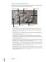


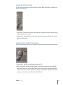
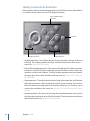

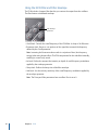


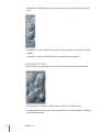
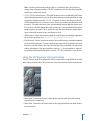


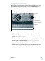
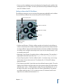


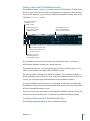

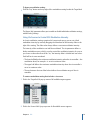
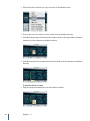
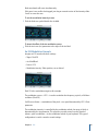


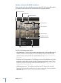

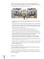
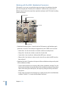
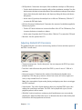
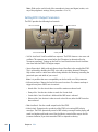

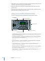
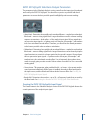
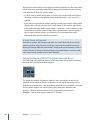
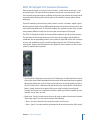
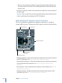
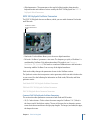
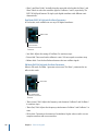

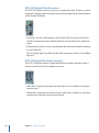

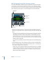

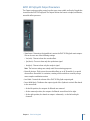

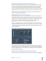


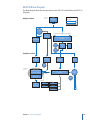

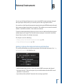


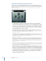
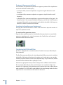
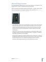
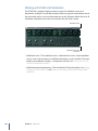
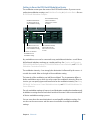
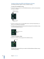

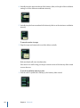

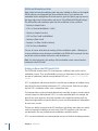
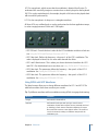
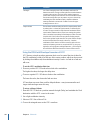
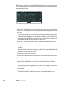


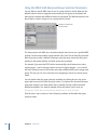
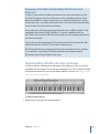

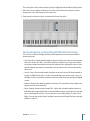
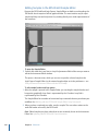


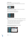
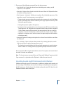
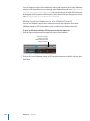
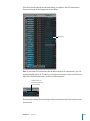


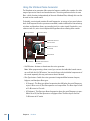


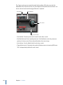


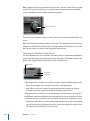
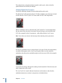


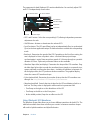
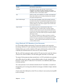
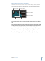
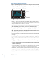
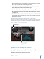


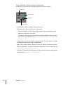
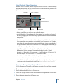

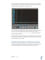
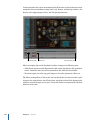
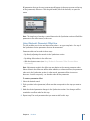
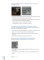


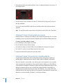


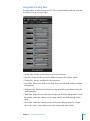
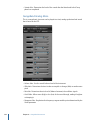
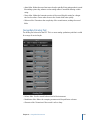
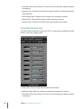
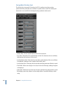

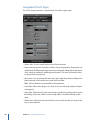
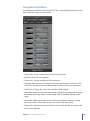
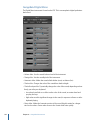
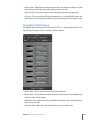
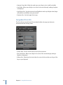
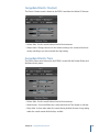
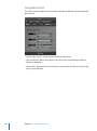
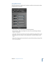
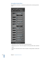

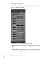

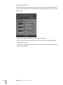
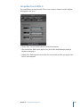


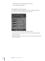
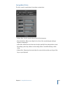
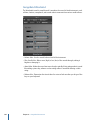

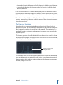


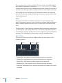

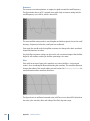
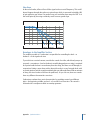

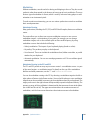


![[English] 1 MB](http://vs1.manualzilla.com/store/data/005724727_1-d0907da86b06d0402fef0dce028404c5-150x150.png)