1
Operator’s Manual
FB 3000 Series Instrument
with Intalogix Technology
Models: FB 3000
© 2005 by Fairbanks Scales Inc.
All rights reserved
50743
Issue 1 05/05
Amendment Record
FB 3000 Series Indicators
with Intalogix Technology
50743
Manufactured by Fairbanks Scales Inc.
821 Locust
Kansas City, Missouri 64106
Issue 1
50743
05/05 New Product
2
05/05
Issue 1
Copyright
This document contains proprietary information protected by copyright. All rights are reserved, no part of this manual
may be reproduced, copied, translated or transmitted in any form or by any means without prior written permission of the
manufacturer.
Trademarks
IBM, EGA, VGA, XT/AT, OS/2 and PS/2 are registered trademarks of International Business Machine Corporation
Award is a trademark of Award Software International, Inc RTL is a trademark of Realtek Semi-Conductor Co., Ltd.
VIA is a trademark of VIA Technologies, Inc.
Winbond is a trademark of Winbond Technology, Inc.
CF and CompactFlash are trademark of ScanDisk Corporation.
Microsoft, Windows, Windows NT, Windows XP, and MS-DOS are either trademarks or registered trademarks of
Microsoft Corporation.
All other product names mentioned herein are used for identification purpose only and may be trademarks and/or registered trademarks of their respective companies.
Disclaimer
Every effort has been made to provide complete and accurate information in this manual.. However, although this manual may include a specifically identified warranty notice for the product, Fairbanks Scales makes no representations or warranties with respect to the contents of this manual, and reserves the right to make changes to this manual without notice
when and as improvements are made.
It is the responsibility of the requesting party to develop, maintain, install, and connect networking devices and general
network connectivity as it applies to the originating party’s network. No warranty or guarantee, expressed or implied,
concerning the network, its design, its installation, or operational characteristics has been offered by Fairbanks Scales.
Fairbanks Scales shall not be liable for any loss, damage, cost of repairs, incidental or consequential damages of any
kind, whether or not based on express or implied warranty, contract, negligence, or strict liability arising in connection
with the design, development, installation, or use of an intended network.
50743
3
05/05
Issue 1
Advanced Weighing Systems, Inc.
License Agreement for INTERACT® VERSION 4
ADVANCED WEIGHING SYSTEMS, INC. ("AWS") IS WILLING TO LICENSE THE SOFTWARE IDENTIFIED BELOW TO YOU
(EITHER AN INDIVIDUAL OR A SINGLE BUSINESS ENTITY, HEREAFTER "YOU" OR "LICENSEE") ONLY UPON THE CONDITION
THAT YOU ACCEPT ALL OF THE TERMS CONTAINED IN THIS LICENSE AGREEMENT ("AGREEMENT"). PLEASE READ THE
AGREEMENT CAREFULLY. BY DOWNLOADING OR INSTALLING THIS SOFTWARE, YOU ACCEPT THE TERMS OF THE
AGREEMENT. INDICATE ACCEPTANCE BY SELECTING THE "ACCEPT" BUTTON AT THE BOTTOM OF THE AGREEMENT. IF
YOU ARE NOT WILLING TO BE BOUND BY ALL THE TERMS, SELECT THE "DECLINE" BUTTON AT THE BOTTOM OF THE
AGREEMENT AND THE DOWNLOAD OR INSTALL PROCESS WILL NOT CONTINUE.
1. DEFINITIONS. "Software" means the identified above in binary form, any other machine readable materials (including, but not limited to, libraries, source files, header files, and data files), any updates and/or upgrades or error corrections provided by AWS, and
any user manuals, programming guides and other documentation provided to you by AWS under this Agreement.
2. LICENSE TO USE. Subject to the terms and conditions of this Agreement, and upon payment of the then-current license fee or
fees (without license fees for certain INTERACT versions), AWS grants you a non-exclusive, non-transferable, limited license to install
and execute internally one copy of the Software for your own personal, individual use. You may install the single copy on one hard
disk or other storage device for one computer, and you may access and use the Software at that location so long as only one copy of
the Software is in operation. If you are a private business rather than an individual, you may authorize the personnel associated with
your business to use the Software, but only one person at a time, on one computer at a time.
3. RESTRICTIONS. Software is confidential and copyrighted. Title to Software and all associated intellectual property rights is
retained by AWS and/or its licensors. You may not rent, lease, lend, modify, decompile, or reverse engineer Software, except and
only to the extent that such activity is expressly permitted by applicable law notwithstanding this limitation. Licensee acknowledges
that Software is not designed or intended for use in the design, construction, operation or maintenance of any nuclear facility.
Advanced Weighing Systems, Inc. disclaims any express or implied warranty of fitness for such uses. No right, title or interest in or to
any trademark, service mark, logo or trade name of AWS or its licensors is granted under this Agreement.
4. LIMITED WARRANTY. AWS warrants to you that for a period of ninety (90) days from the date of purchase, as evidenced by a
copy of the receipt, the media on which Software is furnished (if any) will be free of defects in materials and workmanship under normal use. Except for the foregoing, Software is provided "AS IS". Your exclusive remedy and AWS's entire liability under this limited
warranty will be at AWS's option to replace Software media or refund the fee paid for Software. Any implied warranties on the
Software are limited to 90 days. Some states do not allow limitations on duration of an implied warranty, so the above may not apply
to you. This limited warranty gives you specific legal rights. You may have others, which vary from state to state.
5. DISCLAIMER OF WARRANTY. UNLESS SPECIFIED IN THIS AGREEMENT, ALL EXPRESS OR IMPLIED CONDITIONS, REPRESENTATIONS AND WARRANTIES, INCLUDING ANY IMPLIED WARRANTY OF MERCHANTABILITY, FITNESS FOR A PARTICULAR PURPOSE OR NON-INFRINGEMENT ARE DISCLAIMED, EXCEPT TO THE EXTENT THAT THESE DISCLAIMERS ARE
HELD TO BE LEGALLY INVALID.
6. LIMITATION OF LIABILITY. TO THE EXTENT NOT PROHIBITED BY LAW, IN NO EVENT WILL AWS OR ITS LICENSORS OR
SUPPLIERS BE LIABLE FOR ANY LOST REVENUE, PROFIT OR DATA, OR FOR SPECIAL, INDIRECT, CONSEQUENTIAL, INCIDENTAL OR PUNITIVE DAMAGES, HOWEVER CAUSED REGARDLESS OF THE THEORY OF LIABILITY, ARISING OUT OF OR
RELATED TO THE USE OF OR INABILITY TO USE (INCLUDING BUT NOT LIMITED TO ANY AUTOMATIC DISABLING OF) SOFTWARE OR DATA, EVEN IF AWS HAS BEEN ADVISED OF THE POSSIBILITY OF SUCH DAMAGES. In no event will AWS's
liability to you, whether in contract, tort (including negligence), or otherwise, exceed the amount paid by you for Software under this
Agreement. The foregoing limitations will apply even if the above stated warranty fails of its essential purpose. Some states do not
allow the exclusion of incidental or consequential damages, so some of the terms above may not be applicable to you.
7. SOFTWARE UPGRADES FROM AWS/TERMINATION. You acknowledge that you may be provided with updates and/or upgrades
from AWS, or features of the Software may download, activate, install, and/or execute applets, applications, software extensions, and
updated and/or upgraded versions of the Software from AWS (collectively "Software Upgrades"), which may require you to accept
updated terms and conditions for installation and/or use, including payment of fees at the then-current rates which may change from
time-to-time as published and/or quoted by AWS. In the event the required fee or fees are not paid when due (or for other violation of
this Agreement), AWS may disable the Software and terminate the license herein, and such disabling and termination may include
time-based deactivation for automatic disabling the Software without notice. If additional terms and conditions are not presented on
installation, the Software Upgrades will be considered part of the Software and subject to the terms and conditions of the Agreement.
8. SUPPORT SERVICES. AWS may provide you with support services related to the Software ("Support Services"). Use of Support
Services is governed by AWS policies and programs described in the user manual, in "online" documentation, and/or in other AWSprovided (or AWS-authorized) materials. Any Software Upgrades provided to you as part of the Support Services shall be considered
Software, and may be subject to updated terms and conditions for installation and/or use, including payment of fees.
50743
4
05/05
Issue 1
9. REGISTRATION. With respect to any technical or business information you provide to AWS as part of any registration of your
license to the Software or in connection with the Support Services, AWS and its assigns may use, transfer, and/or license and/or sublicense such information for its business purposes, including for product support and development, and for marketing. Should you
decide to transmit to AWS by any means or by any media any materials or other information (including without limitation, ideas, concepts or techniques for new or improved services and products), whether as information, feedback, data, questions, comments, suggestions or the like, you agree such submissions are unrestricted and shall be deemed non-confidential and you automatically grant
AWS and its assigns a non-exclusive, royalty-free, worldwide, perpetual, irrevocable license, with the right to sublicense, to use, copy,
transmit, distribute, create derivative works of, display and perform the same.
10. TERMINATION. This Agreement is effective until terminated. You may terminate this Agreement at any time by destroying all
copies of Software. This Agreement will terminate immediately without notice from AWS if you fail to comply with any provision of this
Agreement (including any termination under Section 7 above). Either party may terminate this Agreement immediately should any
Software become, or in either party's opinion be likely to become, the subject of a claim of infringement of any intellectual property
right. Upon Termination, you must destroy all copies of Software.
11. EXPORT REGULATIONS. All Software and technical data delivered under this Agreement are subject to US export control laws
and may be subject to export or import regulations in other countries. You agree to comply strictly with all such laws and regulations
and acknowledge that you have the responsibility to obtain such licenses to export, re-export, or import as may be required
after delivery to you.
12. TRADEMARKS AND LOGOS. You acknowledge and agree as between you and AWS that AWS owns the AWS and INTERACT
trademarks and all AWS and INTERACT-related trademarks, service marks, logos and other brand designations ("AWS Marks"), and
you agree to comply with the AWS Trademark and Logo Usage Requirements which may be located at AWS’s website. Any use you
make of the AWS Marks inures to AWS's benefit.
13. U.S. GOVERNMENT RESTRICTED RIGHTS. If Software is being acquired by or on behalf of the U.S. Government or by a U.S.
Government prime contractor or subcontractor (at any tier), then the Government's rights in Software and accompanying documentation will be only as set forth in this Agreement; this is in accordance with 48 CFR 227.7201 through 227.7202-4 (for Department of
Defense (DOD) acquisitions) and with 48 CFR 2.101 and 12.212 (for non-DOD acquisitions).
14. GOVERNING LAW. Any action related to this Agreement will be governed by Wisconsin law and controlling U.S. federal law. No
choice of law rules of any jurisdiction will apply.
15. SEVERABILITY. If any provision of this Agreement is held to be unenforceable, this Agreement will remain in effect with the provision omitted, unless omission would frustrate the intent of the parties, in which case this Agreement will immediately terminate.
16. INTEGRATION. This Agreement is the entire agreement between you and AWS relating to its subject matter. It supersedes all
prior or contemporaneous oral or written communications, proposals, representations and warranties and prevails over any conflicting
or additional terms of any quote, order, acknowledgment, or other communication between the parties relating to its subject matter
during the term of this Agreement. No modification of this Agreement will be binding, unless in writing and signed by an authorized
representative of each party.
50743
5
05/05
Issue 1
Table of Contents
Section 1: General Information
A. Introduction . . . . . . . . . . . . . . . . . . . . . . . . . . . . . . . . . . . . .
B. Specifications . . . . . . . . . . . . . . . . . . . . . . . . . . . . . . . . . . . .
C. Accessories . . . . . . . . . . . . . . . . . . . . . . . . . . . . . . . . . . . . .
8
8
10
Section 2: Installation
A. General Service Policy
B. Overview . . . . . . . . .
C. Unpacking . . . . . . . . .
D. Instrument Location . .
E. Safety
.........
F. System Verification . . .
.
.
.
.
.
.
11
11
12
12
12
13
....................
.................
....................
....................
....................
....................
....................
....................
....................
14
15
15
15
15
16
17
20
23
.
.
.
.
.
.
.
.
.
.
.
.
.
.
.
.
.
.
.
.
.
.
.
.
.
.
.
.
.
.
.
.
.
.
.
.
.
.
.
.
.
.
.
.
.
.
.
.
.
.
.
.
.
.
Section 3: Programming
A. Menu Navigation . . . . . . . . . . . . .
B. General Programming Instructions
1. Options Menu . . . . . . . . . . .
2. Configuration Menu . . . . . .
3. Service Menu . . . . . . . . . . .
4. Customer Password . . . . . .
C. Options Menu
............
D. Configuration Menu . . . . . . . . . . .
E. Communication Menu . . . . . . . . .
.
.
.
.
.
.
.
.
.
.
.
.
Section 4: Operation
A. Basic Operations Summary . . . . . . .
1. Gross Weighing . . . . . . . . . . .
2. Gross Tare Net Weighing . . . .
3. Inbound / Outbound Summary
4. System Shut down . . . . . . . . .
50743
6
.
.
.
.
.
.
.
.
.
.
.
.
.
.
.
.
.
.
.
.
.
.
.
.
.
.
.
.
.
.
.
.
.
.
.
.
.
.
.
.
.
.
.
.
.
.
.
.
.
.
.
.
.
.
.
.
.
.
.
.
.
.
.
.
.
.
.
.
.
.
.
.
.
.
.
.
.
.
.
.
.
.
.
.
.
.
.
.
.
.
.
.
.
.
.
.
.
.
.
.
.
.
.
.
.
.
.
.
.
.
.
.
.
.
.
.
.
.
.
.
.
.
.
.
.
.
.
.
.
.
.
.
.
.
.
.
.
.
.
.
.
.
.
.
.
.
.
.
.
.
.
.
.
.
.
.
.
.
.
.
.
.
.
.
.
.
.
.
.
.
.
.
.
.
.
.
.
.
.
.
.
.
.
.
.
.
.
.
.
.
.
.
33
33
33
34
35
05/05
Issue 1
50743
Section 5: InterAct Inside
A. Introduction . . . . . . . . . . . . . . . . . . . . . . . . . . . . . . . . . . . . .
B. Specifications . . . . . . . . . . . . . . . . . . . . . . . . . . . . . . . . . . . .
37
37
Section 6: Service and Maintenance
A. Remote Service and Diagnostics . . . . . . . . . . . . . . . . . . . . .
B. Errors
......................................
39
41
Section 7: Parts List
A. Recommended Spare Parts . . . . . . . . . . . . . . . . . . . . . . . . .
42
APPENDIX I: Data Output
A. Remote Display Output . . . . . . . . . . . . . . . . . . . . . . . . . . . .
B. Configure Output . . . . . . . . . . . . . . . . . . . . . . . . . . . . . . . . .
1. Fairbanks Data Format . . . . . . . . . . . . . . . . . . . . . . . .
2. Toledo Data Format . . . . . . . . . . . . . . . . . . . . . . . . . .
3. Cardinal 738 Continuous Scoreboard Data Format . . .
4. Weightronix Data Format . . . . . . . . . . . . . . . . . . . . . .
5. Condec Data Format . . . . . . . . . . . . . . . . . . . . . . . . .
44
44
44
45
46
46
47
7
05/05
Issue 1
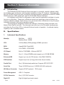
Section 1: General Information
A.
Introduction
The Fairbanks FB 3000 Solutions Series instrument is a powerful, versatile, indicator which
has flexibility, open architecture, and integrated capabilities of many PC functions. With these abilities, the FB 3000 can provide many connectivity and data acquisition capabilities via RS232, RS485,
RS422 serial port, USB, parallel port, and PCI 10/100 Mbs Ethernet interfaces.
An integrated e-mail client is configurable to alert a service organization / individual of a problem prior to total failure. These error notifications include such warnings as load cell failure, low
memory, calibration change, Flash memory error, and several other notifications to keep the proper
individuals informed of the scale’s operating condition.
The instrument is designed to function with IntalogixTM Technology, analog load cells, and
Mettler Toledo DigiTol load cells. The instrument can control up to four (4) scales simultaneously
and utilize the Gross Only, GTN, or Inbound / Outbound modes of operation. A multiscale viewing
capability is also a standard feature.
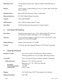
B.
Specifications
1.
Instrument Specifications
Model(s)
Mild Steel
(24737)
Stainless Steel (24900)
CPU
VIA Ezra/Eden (ECBA package) 400Mhz processor
BIOS
Award® 256K Flash BIOS
Chipset
VIA VT8606 + VT82C686B
I/O Chipset
Built-in VT82C686B + Winbond 83977EF
Memory
One (1) 144-pin SDIMM socket support up to 512 MB SDRAM
Enhanced IDE
Support up to two (2) IDE devices ( Ultra DMA 33/66/100)
FDD Interface
Supports up to two (2) floppy disk drives (34-pin header)
Parallel Port
One (1) Bi-directional parallel port. Supports SPP/ ECP/ EPP
Serial Port
Three (3) RS232 and one (1) RS232/ 422/ 485 serial ports
KB/ Mouse Connector
Supports PC/AT keyboard
Power Management
APM 1.1 Compliant
PC/104 Connector
One (1) PC/104 Connector
Digital I/O
Eight (8) digital inputs and outputs
50743
8
PS/2 mouse
05/05
Issue 1
Watchdog Timer
Can generate a system reset. Supports software selectable time-out
interval.
Battery
Lithium battery for data retention up to ten (10) years under normal operating conditions.
Software Driver
Microsoft® XP Professional, Home, or Embedded
Ethernet Interface
PCI 100/10 Mbps Ethernet Controller
Chipset
Dual Intel® 82559ER
SDD Interface
One (1) 50-pin Compact FlashTM socket
Hard Drive
40 GB Industrial Hard drive backed by Compact FlashTM.
2.
Flat Panel/ CRT Interface
Resolution
Flat panel display support up to 1024 x 768 @ 18bpp TFT panel and
CRT monitors to 1024 x 768 16bpp or 120 x 1024 @ 8bpp.
Interface
4x AGP VGA/LCD interface, support for 9,12,15,18,24,36 bit TFT and
optional 15 or 24 bit DSTN panels.
Display Memory
Shares system memory 8/ 16 / 32MB.
Chipset
VIA Twister chip with integrated Savage 4 2D/ 3D/ Video Accelerator
3.
Scale Specifications
Number of scales
Up to four (4) scales simultaneously utilizing IntalogixTM
Technology.Maximum of two (2) scales with Analog Interface
Load cells
Up to 40 load cells maximum utilizing IntalogixTM Technology
Analog Interface
Excitation
Sense Requirement
Analog Filter
Maximum of 10 - 350 ohm load cells
Maximum of 16 - 700 / 1000 ohm load cells
10 Vdc @ 1A
> 25 feet
Light to Heavy
Display
10.4” SVGA Color LCD-TFT with optional Touch Screen.
Display Resolution
640 x 480
50743
9
12/04
Issue 1
Remote Configuration
Integrated Web Browser allows for configuration from a remote
location.
Display Rate
0.1 to 10 seconds in 0.1 intervals
Zero
Disabled, 2% or 100%
Tare
Tare Enabled (AutoTare and Keyboard Tare), Disabled
Auto Clear Tare
Yes or No
Units
lb, lb/kg, lb/ton, lb/tonne, kg, kg/lb, kg/ton, kg/tonne, ton, ton/lb,
ton/kg, ton/tonne, tonne, tonne/lb, tonne/kg, and tonne/ton.
Division Size
.001 through 100. Dual Range selection available.
Motion Band
0.5d, 1.0d, 2.0d, and 3.0d
Auto Zero Tracking
Off, 0.6d, 1.0d, 2.0d, and 3.0d
Filter Factor
Off, Light, Medium-Light, Medium, Heavy-Medium, and Heavy
4.
Environmental
Power Supply
+5 (4.75V to 5.25V), +12(11.4V to 12.6V)
Max Power Requirements
4A @ 5V, 200mA/ +12V ( No Scale Attached)
Operating Temperature
-10 to 104 F (0 to 40 C) Fanless
C.
Accessories
1.
Acc 2001-1A
Pit Power Supply
2.
Acc 2000-1
Smart Sectional Controller
3.
Acc 2000-2
Digital / Analog Smart Sectional Controller
4.
Acc 2000-F
Smart Sectional Controller with Float Switch
5.
Touch Screen Kit (25544)
6.
Intalogix Kit (25542)
7.
Analog Kit (25543)
50743
10
12/04
Issue 1
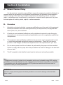
Section 2: Installation
A.
General Service Policy
It is the customer / operator's responsibility to ensure the equipment provided by Fairbanks is
operated within the parameters of the equipment's specifications and protected from accidental or
malicious damage. Other than the procedures authorized in this Operating manual, no service,
repair, or adjustments may be performed by unauthorized / untrained service personnel. Any unauthorized repairs will void any verbal, implied, or written warranties.
B.
Overview
1.
Absolutely no physical, electrical, or program modifications are to be made to this equipment.
Electrical connections other than those specified may not be performed, and physical alterations (holes, etc.) are not allowed.
2.
All electronic and mechanical calibrations and/or adjustments required to make this equipment perform to accuracy and operational specifications are to be completed by qualified service personnel.
3.
The equipment, when installed by qualified service personnel, may be programmed to meet
or exceed any applicable weights and measures requirements. Check with your service
provider or local Weights and Measures Department as to the requirements for your area.
4.
Do not remove power from this unit unless it is performed by the proper shut down method.
Failure to comply with the proper shut down procedures can result in damage to the hard disk
drives or data.
5.
The AC receptacle / outlet shall be located near the instrument and easily accessible.
Note :
The equipment consists of printed circuit assemblies which must be handled using ESD handling
procedures, and must be replaced as units. Replacement of individual components is not allowed.
The assemblies must be properly packaged in ESD protective material and returned intact for
replacement credit per normal procedures.
WARNING:
Failure to comply with the proper shut down procedures can result in damage to the hard disk
drives or data.
50743
11
05/05
Issue 1
C.
Unpacking
1.
Check that all components are on hand and agree with the equipment order.
2.
Remove all components from their packing material, checking to make certain that all parts
are accounted for and no parts are damaged. Advise the shipper immediately if damage has
occurred. Keep the shipping container and packing material for future use. Check the pack
ing list.
3.
Collect all necessary installation manuals.
D.
Instrument Location
1.
The Instrument should be positioned away from direct sunlight.
2.
Avoid areas which have extreme variations in room temperatures. Temperatures outside the
instrument’s specifications will effect the weighing accuracy of this product.
3.
Work areas should be relatively free from drafts and vibrations.
4.
Do not locate near magnetic material or equipment/instruments which use magnets in their
design.
E.
Safety
As is the case with any material handling equipment, certain safety precautions should be
observed during operation:
1.
Never load the platform beyond its rated capacity. Refer to the rating on the serial number
plate of the platform.
2.
Ensure that any structure which supports the platform is capable of withstanding the weight of
the platform plus its rated capacity load.
3.
Do not load the platform if there is any evidence of damage to the platform or supporting
structure.
4.
Use safety chains or other suitable restraining devices if there is any possibility of the load
shifting, falling, or rolling from its position on the platform.
50743
12
05/05
Issue 1
F.
System Verification
When the wiring connections from the load cell(s) to the SSCs or DSSCs to the PPS and on
to the instrument have been completed and inspected, the following verification checks should be
made before continuing.
a.
Power up the instrument while observing the display. The bottom of the screen will
display this legend: "CELLS FOUND" followed by the number of all cells it finds in the
system. This verifies the communications to the Smart Sectional Controllers or
Digital/Analog Smart Sectional Controllers to be correct. A "CELLS FOUND - NONE"
display (failure) at this step typically identifies a wiring problem. Remove power on a
failed test as soon as you have noted the "CELLS FOUND" sequence, and any cells
that may be found are noted. Recheck all interface wiring.
b.
Unusual "CELLS FOUND" numbers, such as 1, 2, 3, 4, 7, 8, 31, 32, usually indicate
an improper address setting in the SSCs or DSSCs that has the odd readings, in this
case Section # 3. Check the dip switch addresses set in each SSC or DSSC that is
not "found" or has unusual cell numbers.
50743
13
05/05
Issue 1
Section 3: Programming
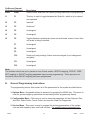
A.
Menu Navigation
OnScreen External
Keyboard Keyboard
Arrows
Arrows
Description
These keys move the cursor in the display in the direction indicated.
They are also used for scrolling.
Menu
Esc
Zero
Pause Break This key zeroes the scale.
Print
Prt Sc
When pressed, a ticket will be printed. In the Data Terminal mode, an
Inbound or Outbound Gross ticket. A Gross, Tare, Net ticket may also be
printed. In the Weigh Only mode, a Gross Weight ticket may be printed
with a manually entered Tare and the Net will be calculated.
Units
Scroll Lock
Changes the units of weight displayed, depending on the selection made
in the Calibration Menu.
0 to 9
0 to 9
Used to enter numeric data, such as tares and IDs.
50743
This key changes the display to the Operation Menu. This key can also
be used to return the display to the last menu screen that was shown.
14
05/05
Issue 1
OnScreen External
Keyboard Keyboard
Enter
Enter
Description
Used to store selections into memory during data entry or programming.
f1
F1
This key is used to toggle between the Scale No. which is to be viewed
and operated.
f2
F2
Inbound*
f3
F3
Outbound*
f4
F4
Unassigned
f5
F5
Unassigned
f6
F6
Toggles between operational screen and multi-scale screen if more than
one scale is being controlled..
F7
Unassigned
F8
Unassigned
F9
Unassigned
F10
Scale port/ parity settings. Allows manual changes of port assignment
and parity.
F11
Unassigned
F12
Unassigned
Note:
The indicator can be set up to operate in one of three modes: GROSS weighing, GROSS, TARE,
NET weighing or IN/OUT weighing dependent upon service programming. These keys are not
functional unless IN/OUT weighing has been programmed.
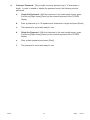
B.
General Programming Instructions
The programming menus that contain all of the parameters for the system are listed below.
1. Options Menu - Accessible without a password by pressing the MENU key. This menu is
used for general weighing operations and accessing further programming menus.
2. Configuration Menu - This menu is used to enter the parameters for the Keyboard Tare,
AutoTare, Select Scale, Format Ticket, and view the Load Cell Diagnostics.
3. Service Menu - This menu is used to program the technical parameters of the system,
such as scale capacity, span, and load cell data. For qualified service personnel only.
50743
15
05/05
Issue 1
4.
50743
Customer Password - This provides a security password up to 10 characters in
length. In order to enable or disable the password mode, the following must be
performed.
a.
Create the Password - With the instrument in the main weigh screen, press
[Left Arrow] [Right Arrow] [Enter] on the external keyboard or the FB 3000
display.
b.
Enter a password up to 10 alphanumeric characters in length and press [Enter].
c.
The password is saved and ready for use.
d.
Delete the Password - With the instrument in the main weigh screen, press
[Left Arrow] [Right Arrow] [Enter] on the external keyboard or the FB 3000
display.
e.
Enter a blank password and press [Enter].
f.
The password is saved and ready for use.
16
05/05
Issue 1
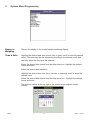
C.
Options Menu Programming
Return to
Weighing
Returns the display to the normal weight processing display.
Time & Date
Highlight the desired date item (month, day or year), scroll or enter the desired
value. The date may also be selected by scrolling to the desired month and
year and select the day upon the calendar.
Select the desired date format from the drop down-box. Highlight the desired
format and enter.
Select the desired date separator.
Highlight the desired time item (hour, minutes, or seconds), scroll or enter the
desired value.
Select the desired date format from the drop-down box. Highlight the desired
format and enter.
The revision number at the top right of the screen is the program version
number.
50743
17
12/04
Issue 1
Ticket Number Enter the ticket number required via the indicator’s numeric keypad or through
an external keyboard accessory.
Keyboard Tare This feature allows a manually-entered tare. This feature is enabled through
service programming.
AutoTare
This feature will store the tare of the item on the scale when selected. This feature is enabled through service programming.
Audit Trail
This display shows the time and date when the calibration or configuration
programs were changed. The first column is the number of the platform, followed
by the time and date the change was made. The Count column shows the
number of times the platform has been calibrated or configured. cThis display is
updated automatically with each calibration or configuration change. cIt cannot
be changed manually.
50743
18
12/04
Issue 1
Configuration
Menu
This menu accesses general configuration functions of the indicator.
Service Menu
This menu accesses calibration and other metrological functions of the indicator.
The Service menu is password protected and is restricted to authorized service
personnel only.
Check for
Updates
This feature allows the FB 3000 to obtain updated files when it is connected to
the Internet.
Operators
Manual
This accesses the PDF version of the operator’s manual stored on the indicator
for reference.
50743
19
05/05
Issue 1
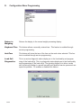
D.
Configuration Menu Programming
Return to
Weighing
Returns the display to the normal weight processing display.
Keyboard Tare This feature allows a manually entered tare. This feature is enabled through
service programming.
AutoTare
This feature will store the tare of the item on the scale when selected. This feature is enabled through service programming.
Load Cell
Diagnostics
This is a service diagnostic status display as to the functionality and programming of the load cell(s). This is a diagnostic status display as to the functionality
and programming of the load cell(s). The ghosting feature is to allow a scale
with a load cell problem to operate normally until qualified service personnel can
repair the problem. F6 enables or disables this feature.
50743
20
05/05
Issue 1
Communication This menu accesses general communication functions of the indicator.
Ports
See Communications Menu for more details.
View / Delete
Tares
This menu allows modifications to existing tares by changing the tare value or
deleting a tare entry, one at a time.
Edit Loop
Prompt
The Loop ID prompt may be changed or customized for a application. The
prompting text may be changed by entering up to a maximum of 10
characters. i.e. Truck ID, Railcar ID, License No, and etc.
50743
21
05/05
Issue 1
Mouse Properties
50743
The mouse settings may be adjusted to personal preferences of
operation.
22
05/05
Issue 1
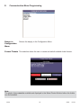
E.
Communication Menu Programming
Return to
Configuration
Menu
Returns the display to the Configuration Menu.
Format Tickets This selection allows the user to create and edit all available ticket formats.
Note:
The printer drivers must be available and displayed in the Select Printer Window before the tickets
can be formatted.
50743
23
05/05
Issue 1
1.
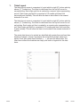
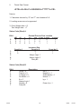
Ticket Layout
The ticket layout screen is comprised of a grid which is eight (8”) inches wide by
eleven (11”) inches long. The ticket is referenced from the top left corner for
normal printing. Each major grid line is marked by a numeric value representing
an inch. Each major grid block is comprised of 16 smaller grid lines both
horizontally and vertically. This will allow the data to be located to the nearest
sixteenth of an inch.
The ticket layout screen is comprised of a grid which is eight (8”) inches wide by
eleven (11”) inches long. The ticket is referenced from the top left corner for normal printing. Each major grid line is marked by a numeric value representing an
inch. Each major grid block is comprised of 16 smaller grid lines both horizontally and vertically. This will allow the data to be located to the nearest sixteenth of
an inch.
The actual data items to be printed are identified with greater than and less than
brackets. Example: <Gross> represents the actual Gross weight value to be
printed. Each item within these brackets, < >, will print the actual data. The
other items without the brackets are simply text items or legends for the data
items.
50743
24
05/05
Issue 1
2.
Options Button
a.
50743
Options\ Edit Properties
A Properties window for each data item may be accessed by right clicking the
data item or pressing the [Options] button and selecting Edit properties. The
properties for each field may be individually set, i.e. Coordinate settings top and
left, Alignment, Borders, Color, and Font size and type. There is a maximum of
40 report fields available for each ticket. This includes the first 18 report fields
which are pre-defined system fields.
1.
This displays the field to be added or changed.
2.
This provides access to a drop down list to change items to edit.
3.
The visible check box, if checked, allows the item to be displayed
and printed. Otherwise the item is hidden from viewing and will not print.
4.
The Auto Size feature allows the field to grow as needed.
5.
The Top data item is the data field placement value on the display in
pixels. It is measured from the top of the display down.
Definition: 97 pixels = ~1 inch
6.
The Left data item is the data field placement value on the display in
pixels. It is measured and increases from the left of the display towards
the right.
Definition: 97 pixels = ~1 inch
7.
The Height value is measured in pixels and is determined by the font
selected. If this value is manually changed, the display will not show it
unless the item is selected by a left mouse click and the box surrounding
the data item will be either larger or smaller.
8.
The Alignment box allows for the selection of whether the data item
selected is Left Justified, Center Justified, or Right Justified.
25
05/05
Issue 1
9.
The Width value is measured in pixels and is determined by the font
selected. If this value is manually changed, the display will not show it
unless the item is selected by a left mouse click and the box surrounding
the data item will be either larger or smaller.
10.
The Border feature allows the selection of a single line border line to sur
round the data item selected.
11.
The Text field entries are changed or added by entering the text into this
data entry box.
12.
The Font button brings up a window which has a selection of font types,
sizes, enhancements or attributes.
13.
The Color button has a variety of colors to customize the colors of the
data item selected.
14.
The Apply button saves and applies the changes.
15.
The OK button will save, apply the changes made, and exit the Add/
Change Text Properties.
b.
Options\ Add Text Field
Selecting this option will open the Add/ Change Text Properties window and it will
select the next available text field to be available to add to the ticket.
c.
Options\ Keep Fonts the Same
Selecting this option will make all data items the same font type and size.
d.
Options\ Properties on Top
Selecting this option will place the Add/ Change Text Properties on the top of the Ticket
Layout screen. Each time a data item is selected the Add/ Change Text Properties will
open.
50743
26
05/05
Issue 1
e.
Options\ Snap to Grid
Selecting this option will cause the data item being moved to align itself to the nearest
grid line position.
f.
Options\ Spacing = 10
Selecting this option opens the Enter Grid Spacing window. The grid spacing may be
changed from the default value of 10. The grid spacing value is selectable by entering
a value from 2-20.
g.
Options\ Edit Layout
h.
Options\ Close
This selection closes the Edit Ticket Layout and exits to the Format Ticket Menu.
3.
50743
Ticket Format Procedure
a.
Select the printer desired from the Select Printer window. Choose and press
the [F1-Inbound Format], [F2-Outbound Format], or [F3 -G-T-N Format] button
to select the desired ticket to format.
b.
Choose and Press the [F1-Inbound Format], [F2-Outbound Format], or
[F3 -G-T-N Format] button to select the desired ticket to format.
c.
Press the [Format Ticket [F5]] button to format the ticket.
d.
The format grid will appear on the display along with data items. The data items
may be placed on the grid utilizing the drag and drop method.
27
05/05
Issue 1
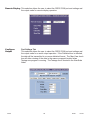
Remote Display This selection allows the user to select the RS232 COM port and settings and
the output mode for remote display operation.
Configure
Output
50743
Port Settings Tab
This selection allows the user to select the RS232 COM port and settings and
the output mode for a serial output operation. If the Delimited box is checked,
the data will be transmitted in a comma delimited format. The Map View check
box will allow viewing of the data in the memory mapped location when
Testapp.exe program is running. The Testapp.exe is located in the NewScale
folder.
28
05/05
Issue 1
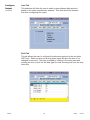
Configure
Output
continued
Load Tab
This selection will allow the user to select a preconfigured data protocol
based on the scale manufacturer selected. This item should be selected
first when configuring the output.
Build Tab
This tab allows the user to configure the data string protocol order and enter
ASCII text. Select an item and a drop-down menu will allow the item to be
changed or removed. Text may be added by clicking in the value area and
entering the text or click into the data type box and choosing text from the drop
down box.
50743
29
05/05
Issue 1
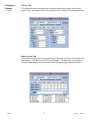
Configure
Output
continued
Tokens Tab
This selection allows programming of various data string tokens such as the
motion flag. The tokens are set as required for the data protocol requirements.
Status Codes Tab
This selection allows for the programming of data bits for status words within the
data stream. The Status code is 8 bits in length. The data may be entered in
the blank data entry position and the loaded by pressing the [Loaded] button.
50743
30
05/05
Issue 1
Configure
Output
continued
View Printers
50743
Weights Tab
This selection allows programming of the specific values for the weight tokens.
tokens. The selection of weight digits is available from 5 to a maximum of 7
digits. The decimal point allows for the placement of a decimal point. The dropdown box lists None, Floating, Fixed, and Trailing. The polarity may also be
selected and included in the data string.
This selection allows the user to see a list of available printers.
31
05/05
Issue 1
Add a Printer
50743
This selection will allow the user to add a printer driver from the list of available printers or use another source if required. This utilizes the Windows XP
Add a Printer functions and wizards.
32
05/05
Issue 1
Section 4: Operation
A.
Basic Operations Summary
There are three modes of operations available, Gross Weighing, Gross-Tare-Net Weighing
and Inbound - Outbound Weighing. The operating mode is a service-programmable item
only.
1.
2.
Gross Weighing
a.
Press the [ZERO] key to zero the scale.
b.
Place the object to be weighed on the platform. At a stable display, press
the [PRINT] key and a Gross Weight Ticket will be printed.
Gross-Tare-Net Weighing
a.
Press the [ZERO] key to zero the scale.
b.
Place the empty container on the platform.
c.
Choose TARE or AUTO TARE at the menu.
1.
If TARE is selected, enter the known Tare Weight through the keypad.
2.
If AUTO TARE is selected, when the display is stable, press the
[ENTER] key. The weight will be stored as a Tare Weight.
d.
Remove the container from the platform and fill it with the product to be
weighed.
e.
Place the filled container back onto the platform.
f.
Press the [PRINT] key and a Gross-Tare-Net Ticket will be printed.
g.
Mode Change - When a TARE or AUTO TARE is entered, the scale
automatically switches from the Gross Weighing Mode to the Gross-TareNet Mode. To change the scale from the Gross-Tare-Net Mode back to
the Gross Weighing Mode, enter a zero (0) Tare from the keypad.
Note:
If the display shows load cell(s) bad, this indicates the weight on the platform has changed from the
calibration zero. Check the platform for equipment, debris, or other materials and remove them.
Press the ZERO key a second time to return to the WEIGH MODE.
50743
33
05/05
Issue 1
3.
INBOUND / OUTBOUND Weighing Mode Summary
INBOUND / OUTBOUND weighing consists of weighing an item, inbound, either full
or empty, then weighing the same item outbound, full or empty, and printing a ticket
with the two weights shown. The two weights for the same container, an inbound
weighment with a stored tare, or an outbound weighment with a stored tare, are called
a complete transaction. An inbound weighment with NO outbound weighment is an
incomplete transaction.
a. Basic In/Out Weighing
i. With the indicator powered up, press the [ZERO] key.
ii. Place the item to be weighed on the platform. This will be the INBOUND
weighment.
iii. Press the [F2] INBOUND key.
iv. The display will prompt the operator for a LOOP ID. This is the identification number that will be used to identify the complete transaction. Enter the ID number to be
used through the keypad and press the [ENTER] key. This LOOP ID number will be
used again to recall the outbound weighment.
v. An INBOUND ticket will be printed if an INBOUND ticket format is programmed.
The data for this partial transaction will be stored in the indicator with the LOOP ID
number as the transaction recall label.
vi. Remove the container from the platform. Material can be added or removed from
the container.
To complete the transaction:
vii. Move the container back onto the platform. Press the [F3] OUTBOUND key.
viii. The display will prompt the operator for the LOOP ID that was entered for this
transaction on the inbound weighment. Enter the same LOOP ID through the keypad
and press the [ENTER] key. Press the [PRINT] key.
ix. The indicator will retrieve the inbound data from memory and combine it with the
new outbound data and an INBOUND / OUTBOUND ticket will be printed. The data is
stored as a complete transaction.
50743
34
05/05
Issue 1
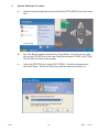
4.
50743
System Shutdown Procedure
a.
Using the external keyboard, press and hold the [CTRL] [ESC] keys at the same
time.
b.
The Task Bar will appear at the bottom of the display. Using the mouse, right
click on the FB 3000 icon in the lower Task Bar and select CLOSE or [ALT] [F4].
The FB 3000 will close down properly.
c.
Select the [START] button, select SHUT DOWN. A window will appear and
show Shut Down. Select the [OK] button and the instrument will turn off.
35
05/05
Issue 1
d.
Upon shut down, the display will remain illuminated. Turn the power switch off
which is located on the bottom left side of the instrument.
e.
The indicator has been properly turned off.
WARNING!
Improper shutdown of this instrument can cause damage to hard drive and loss of data.
50743
36
05/05
Issue 1
Section 5: InterAct Inside
A.
Introduction
InterAct Inside is a database scale transaction software application. InterAct Inside software installation files are loaded on every FB 3000 instrument as part of the standard FB 3000 instrumentation.
It is also available in several different versions offering different features and as standalone software
for a desktop or laptop computer. Only InterAct Inside is included with the FB 3000 indicator. Other
versions of InterAct must be purchased separately.
InterAct Inside is designed for use in the collection, storage, and reporting of weight-related data.
The software is intended for truck scale applications, but is flexible enough to be used for railroad
track scale and floor scale applications.
The differences between the different versions of InterAct are provided in some key points for clarification:
InterAct Inside – is loaded on every FB 3000 instrument as part of the standard FB 3000 at no
additional charge. It has tables for vehicles, material and pricing, and customers. InterAct steps the
operator through a sequence of events to process a transaction, including printing a ticket, if
required. It can be upgraded to Standard or Professional after the initial installation if the customer’s
needs evolve. Contact your local Fairbanks Service Center for more details regarding installation.
InterAct Limited – In PC applications, InterAct offers customers the flexibility of a computer running
Windows with the ability to configure data tracking operations to meet their present needs. InterAct
gives the customer file storage capabilities that can only be achieved outside a conventional scale
instrument. Basically the same version as InterAct Inside except in a version to be installed on a
desktop or laptop computer. It can be upgraded Standard or Professional after the initial installation
if the customer’s needs evolve.
InterAct Standard – Offers job tracking, tax tables for managing tax rates, more flexible reporting
and multiple product/material configuration options. It can be upgraded in the future to Professional
after the initial installation, for additional fees, if the customer’s needs evolve.
InterAct Professional – Offers all of the features of InterAct Standard plus detailed invoicing and
statement functions. This can be installed after the initial installation, for additional fees, if the customer’s needs evolve.
All versions of InterAct are Windows XP compatible software applications.
50743
37
05/05
Issue 1
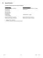
B.
Specifications
Hardware Requirements for InterAct Software
Requirements
Pentium compatible 100 MHz
Windows 95,
Windows 98,
Windows NT,
Windows 2000
Windows XP
64 MB RAM
*Phone Modem
Network EtherNet Connection
Serial port for scale connected
Recommendations **
Pentium compatible 400 MHz or Higher
Windows XP
128 MB RAM or Higher
Network EtherNet Connection
Serial port for scale connected
* Support Plan is required
** FB 3000 instrument meets all requirements.
50743
38
05/05
Issue 1
Section 6: Service and Maintenance
A.
Remote Service and Diagnostics
The FB 3000 has the ability to be serviced and have diagnostics performed from a remote location
such as the nearest authorized Fairbanks Service Center. The instrument must be connected to a
network with internet access. The scale operator simply presses two keys to enable the remote servicing feature and one key to disable. The procedure to enable / disable is listed below.
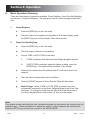
1.
50743
Enable Remote VNC Connection
a.
Left click on the [Fairbanks Globe] then press and release the [Menu] key.
b.
The display will indicate the following window.
39
05/05
Issue 1
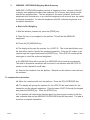
2.
50743
Disable Remote VNC Connection
a.
Left click on the [Satellite with the red medical cross] key.
b.
The display will indicate the following window.
c.
The remote diagnostic box will close and be removed from the display. The
indicator has returned back to normal operations.
40
05/05
Issue 1
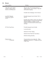
B.
Errors
Error Condition
Solution
Check that scale is empty,
If Scale is empty, Call for
Service, Load Cell(s) bad.
This error will occur if a large amount of
weight is zeroed. This is normal. Press OK
and continue weighing.
Possible load cell damage, Call for Service.
Load Cell Failure(s)
Flashing and display
shows “ - - - - - “.
Possible damaged load cell cable, Call for
Service.
Possible load cell failure. Access the Load Cell
Diagnostics Menu to verify the load cell status
and count stability or change of counts.
Contact your local service for further troubleshooting.
SC Cells Found None
Possible damaged load cell cable.
Load cell shorted.
Defective Pit Power Supply.
Defective Smart Sectional Controller(s).
Defective Analog assembly.
Display shows
“ - - - - - “~ lb GROSS
50743
Communication error to load cells. Check
settings by pressing F10. Settings should be
COM2, Even.
41
05/05
Issue 1
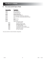
Section 7: Parts
A.
Recommended Spare Parts
Part Number
Description
25241
24885
24886
15056
22610
24888
24713
24899
25316
25424
15745
25369
25548
Hard Disk Drive
Power supply pcb
Embedded SBC pcb
Communication pcb*
Analog interface pcb*
Touchscreen controller pcb
Cover assembly includes display (Mild Steel)*
Cover assembly includes display (Stainless Steel)*
Fuse
Fuse Assembly
Knob
Rocker switch
Cable Kit Assembly includes:
I/O cable assembly
Keyboard extension cable
LVDS Data cable assembly
LPT cable assembly
LCD Backlight cable assembly
PS2 Keyboard- Mouse cable assembly
USB cable assembly
IDE cable assembly
25215
24890
24892
24894
24895
25404
25470
25388
* May vary based on model and indicator configuration.
50743
42
05/05
Issue 1
Appendix I: Data Output
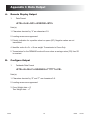
A.
Remote Display Output
1.
Data Format
<STX><4><0><SP/-><XXXXXX><ETX>
Note(s):
1. Characters denoted by “X” are characters 0-9.
2. Leading zeroes are suppressed.
3. Polarity indication for a positive value is a space (SP). Negative values are not
transmitted.
4. Identifier code <4><0> = Gross weight. Transmission is Gross Only.
5. Transmission for the DEMAND mode will occur when a carriage return (CR) Hex 0D
is received.
B.
Configure Output
1.
Fairbanks Data Format
<STX><A><B><C><GGGGGG><TTTTTT><CR>
Note(s):
1. Characters denoted by “G” and “T” are characters 0-9.
2. Leading zeroes are suppressed.
3. Gross Weight data = G
Tare Weight data = T
50743
43
05/05
Issue 1
Status Code (Word) A
Bit #
0
1
2
3
4
5
6
7
x00
0
0
0
x0
1
0
0
x
0
1
0
Count by 1
1
0
Decimal Point or Zero Location
x.x
x.xx x.xxx x.xxxx
x.xxxxx
1
0
1
0
1
1
0
0
1
1
0
1
1
1
1
Increment Size
Count by 2
0
1
Always Logic 1
Always Logic 0
Parity Bit
Count by 5
1
1
Status Code (Word) B
Bit #
0
1
2
3
4
5
6
7
Description
Gross = 0
Positive = 0
In Range = 0
No Motion = 0
lb = 0
Always Logic 1
Normal = 0
Parity Bit
Net = 1
Negative = 1
Overcapacity = 1
Motion = 1
kg = 1
Power Up = 1
Status Code (Word) C
Bit #
0
1
2
3
4
5
6
7
50743
Description
Always Logic
Always Logic
Always Logic
Normal = 0
Always Logic
Always Logic
Normal = 0
Parity Bit
0
0
0
Print Switch Pushed = 1
0
1
Keyboard Tare = 1
44
05/05
Issue 1
2.
Toledo Data Format
<STX><A><B><C><GGGGGG><TTTTTT><CR>
Note(s):
1. Characters denoted by “G” and “T” are characters 0-9.
2. Leading zeroes are not suppressed.
3. Gross Weight data = G
Tare Weight data = T
Status Code (Word) A
Bit #
0
1
2
3
4
5
6
7
x00
0
0
0
x0
1
0
0
x
0
1
0
Count by 1
1
0
Decimal Point or Zero Location
x.x
x.xx x.xxx x.xxxx
x.xxxxx
1
0
1
0
1
1
0
0
1
1
0
1
1
1
1
Increment Size
Count by 2
0
1
Always Logic 1
Always Logic 0
Parity Bit
Count by 5
1
1
Status Code (Word) B
Bit #
0
1
2
3
4
5
6
7
50743
Description
Gross = 0
Positive = 0
In Range = 0
No Motion = 0
lb = 0
Always Logic 1
Normal = 0
Parity Bit
Net = 1
Negative = 1
Overcapacity = 1
Motion = 1
kg = 1
Power Up = 1
45
05/05
Issue 1
Status Code (Word) C
Bit #
0
1
2
3
4
5
6
7
3.
Description
Always Logic
Always Logic
Always Logic
Normal = 0
Always Logic
Always Logic
Normal = 0
Parity Bit
0
0
0
Print Switch Pushed = 1
0
1
Keyboard Tare = 1
Cardinal 738 Continuous Scoreboard Data Format
<CR><P><WWWWWW><m><SP><U><SP><g><SP><SP><ETX>
Note(s):
1.
2.
4.
W = Displayed weight
P = Polarity
+ = Positive weight
- = Negative weight
U = Units
lb = pounds
kg = kilograms
m = Motion or o = Overload
g = Gross; n = Net
SP = Space
Leading zeros are not suppressed.
Weightronix Data Format
< ><M><WWWWWW>< ><U><CR><LF>
Note(s):
1.
2.
50743
< > = Space
M = Mode
G =Gross
T=Tare
N=Net
W = Displayed weight
U = Units
m= Motion
o = Overload
Leading zeros are suppressed.
46
05/05
Issue 1
5.
Condec Continuous Data Format
<STX><P><WWWWWWW><U><G><M><CR>
Note(s):
1.
P = Polarity
space = positive weight
- = negative weight
W = Displayed weight
U = Units
L = pounds
K = kilograms
G = Gross; N = Net
M = Motion
2.
Leading zeros are suppressed.
50743
47
05/05
Issue 1