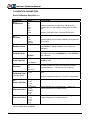
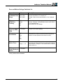
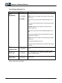
1
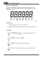
M1 INDICATOR
TECHNICAL MANUAL
SOFTWARE RELEASE 1.41, 09/2009
Copyright © 2008, 2009 Western Scale Co. Limited. All rights reserved.
Published by: Western Scale Co. Limited.
Information in this Installation / Technical Manual is subject to change without
notice due to correction or enhancement. The information described in this
manual is the property of Western Scale Co. Ltd. No part of this manual may be
reproduced or retransmitted in any form, without the expressed written
permission of Western Scale Co. Ltd.
Western Scale Co. Limited
1670 Kingsway Avenue
Port Coquitlam, B.C.
CANADA
V3C 3Y9
Tel: (604) 941-3474
Fax: (604) 941-4020
[email protected]
www.westernscale.ca
FOR TECHNICAL SUPPORT REGARDING THIS PRODUCT, PLEASE CALL
YOUR AUTHORIZED WESTERN DEALER:
Indicator Technical Manual
TABLE OF CONTENTS
INTRODUCTION ............................................................................................................................. 2
Safety .......................................................................................................................................... 2
Features ...................................................................................................................................... 3
Specifications .............................................................................................................................. 3
DISPLAY & ANNUNCIATORS ........................................................................................................ 4
Weight Display ............................................................................................................................ 4
Annunciators ............................................................................................................................... 4
KEYPAD & SCALE FUNCTIONS.................................................................................................... 6
INSTALLATION ............................................................................................................................... 8
Pre-Installation ............................................................................................................................ 8
Opening the M1 Enclosure.......................................................................................................... 8
Load Cell Wiring .......................................................................................................................... 9
Communications Wiring (RS 232)............................................................................................. 10
Remote Switch Wiring ............................................................................................................... 11
Battery / Battery Replacement .................................................................................................. 11
Closing the M1 Enclosure ......................................................................................................... 12
Mounting Instructions ................................................................................................................ 12
START-UP..................................................................................................................................... 13
TIME & DATE ................................................................................................................................ 13
CALIBRATION MODE................................................................................................................... 14
Calibration Keys ........................................................................................................................ 14
Entering Calibration Mode......................................................................................................... 14
Navigating Calibration Parameters ........................................................................................... 15
Editing Calibration Parameters ................................................................................................. 15
Exit & Save Calibration ............................................................................................................. 15
CALIBRATION PARAMETERS..................................................................................................... 16
Scale Calibration Sub-block 1.x ................................................................................................ 16
Zero and Motion Settings Sub-block 2.x ................................................................................... 17
Tare Settings Sub-block 3.x ...................................................................................................... 18
Scale Filtering Settings Sub-block 4.x....................................................................................... 19
Serial Communications Sub-block 5.x ...................................................................................... 20
Serial Communications Sub-block 5.x (Continued) .................................................................. 21
Ticket Formatting Sub-block 7.x................................................................................................ 22
Additional Scale Functions Sub-block 8.x ................................................................................. 23
Scale Diagnostics Sub-block 9.x............................................................................................... 24
QUICK SCALE CALIBRATION ..................................................................................................... 25
REMOTE DISPLAY MODE ........................................................................................................... 26
USER MENU ................................................................................................................................. 28
SEALING THE INDICATOR (LEGAL FOR TRADE) ..................................................................... 29
TROUBLESHOOTING & ERROR MESSAGES............................................................................ 30
1
Indicator Technical Manual
INTRODUCTION
Best suited to bench and floor scales, the M1 is a basic, 5 button indicator that
features the same high resolution and speed found in other Western instruments.
A compact stainless steel enclosure and large display make the M1 perfect for
virtually all light industrial weighing applications while advanced features like time
& date and programmable tickets ensure the M1 will continue to meet customer
requirements into the future.
Western’s continued dedication to durability, functionality, and versatility make
the M1 engineered for the diversity of the weighing industry.
The following User information is for the exclusive use of WESTERN Dealers and
Customers.
Safety
Installation, configuration, and servicing are only to be done by qualified Scale
Service Technicians as authorized by Western.
Power must be disconnected before servicing the unit. Disconnection from the
line voltage is done by disconnecting the mains plug.
This equipment must be connected to a socket-outlet with a protective earthing
connection. The socket outlet shall be installed near the equipment, and shall be
easily accessible.
This equipment is intended for connection to multiple RATED VOLTAGES or
FREQUENCIES. The switchover to the corresponding voltage is done
automatically by the equipment.
CAUTION! HIGH VOLTAGES are present inside the M1
indicator enclosure.
Scale Service Technicians handling M1 PCBs must observe
proper electrostatic discharge (ESD) handling procedures.
ATTENTION! Unauthorized installation and service of this unit
may void the warranty.
2
Indicator Technical Manual
Features
Simple Interface
• Large, easy to read LED display digits (7/8ths inch / 22 mm)
• Oversize keys with international symbols
• 8 Annunciators display scale data
• MENU key accesses tickets and macro functions
Durability
• Compact enclosure with swivel bracket
• 304 stainless steel construction
Excellent Serviceability
• Easy to navigate software menu and calibration
• Calibrate to any test weight value
• Terminal wiring
Advanced Capabilities & Quality
• MACRO II Ticket System
• Time & Date
• 2 Year Warranty
• MADE IN CANADA.
Specifications
Excitation:
Analog Input Range:
Resolution:
Measurement Speed:
5 VDC, Up to 4 x 350 Ω or 8 x 700 Ω load cells
0 - 20 mV
10,000d Class III / IIIL; 20,000d Class IIIHD (Can.)
1 million internal counts
80 weight samples/sec.
Power:
AC Input: 90 - 240 VAC
Consumption: 500 mW
Display:
6 digit, 7 segment LED weight display
8 LED annunciators
Communications:
2 Full duplex RS-232 serial ports
Configurable data format
Selectable output strings
Temperature Range:
14°F to 104°F / -10°C to 40°C
Approvals:
NTEP & Measurement Canada approved
3
Indicator Technical Manual
DISPLAY & ANNUNCIATORS
The M1 uses a high intensity Light Emitting Diode (LED) display with a quick
update rate. The LED annunciator lamps communicate scale status and mode
information to the user.
M1 Display
Weight Display
•
6 digits (7 segments each). Up to 3 decimal points.
•
Negative weights are indicated by a minus sign (-) on the far left character.
Annunciators
CENTRE ZERO: The scale is within ±0.2 graduations of TRUE
ZERO.
MOTION: The scale is in motion.
GROSS: The scale is in GROSS weighing mode.
NET: The scale in NET weighing mode (a tare weight is stored)
4
Indicator Technical Manual
Annunciators (Continued)
lb: The scale is weighing in POUNDS.
kg: The scale is weighing in KILOGRAMS.
oz: The scale is weighing in OUNCES.
g: The scale is weighing in GRAMS.
Some annunciators may not function the same way in Remote
Display Mode. For more information, see page 26.
5
Indicator Technical Manual
KEYPAD & SCALE FUNCTIONS
The M1 indicator utilizes 5 keys for operator interfacing. To maximize indicator
functionality, some keys perform multiple functions.
M1 Keypad
Press the key:
MENU - Cycles through the User MENU to access
additional Scale Tickets and functions (See Pg. 28).
UNITS - Toggles between Primary, Secondary and
Press & hold
the key (2 sec): Tertiary Weighing Units (if enabled).
Alternate Units may be selected or disabled in
Calibration Mode by Qualified Technicians.
Press the key:
GR/NT - Toggles between GROSS and NET
weighing modes if a tare value is stored.
CLEAR - Clears any previously acquired tare
Press & hold
the key (2 sec): values. When used in Legal for Trade
applications, tares can only be cleared when
GROSS weight is at no load.
Clears Peak Hold (locked weight) values when
Peak Hold function is enabled.
6
Indicator Technical Manual
TARE:
Acquires a tare value from weight on the scale
(Container, Box, etc.).
The indicator will not tare if:
•
Weight on the scale is in MOTION;
•
The scale weight is zero or negative;
When one of these situations occurs, the display
will briefly read “Err 2”.
The TARE button may be disabled in Calibration Mode
by Qualified Technicians.
In Canadian Legal for Trade applications, previous tare weights
must be cleared before a new tare weight can be acquired.
ZERO:
Sets the weight display to ZERO.
The indicator will not zero if:
PRINT:
•
Weight on the scale is in MOTION;
•
The weight on the scale exceeds the allowed
ZERO RANGE (Display reads “Err 4”).
Transmits data string or scale ticket through COM1.
NOTE: If multiple tickets are programmed, Ticket 1 is
always assigned to the PRINT key.
7
Indicator Technical Manual
INSTALLATION
Pre-Installation
It is always good practice to verify that your Western M1 indicator is complete
and undamaged upon receipt.
•
Check over packaging for any signs of damage.
•
Remove M1 from protective packaging and check for damage.
•
Verify that the box includes the M1 indicator complete with:
o User Manual;
o Mounting bracket and thumb screws.
Opening the M1 Enclosure
1. Make sure the unit is disconnected from power.
2. Remove the screws from the back of the enclosure.
3. Lift the back cover away from the enclosure. Be sure to observe proper
ESD procedures when handling PCBs.
1.
2.
3.
4.
5.
6.
7.
8.
9.
10
6
5
7
1
M1 PCB
Power Supply Module
Load Cell Terminal Block
Load Cell Jumpers (Sense)
Com1 Terminal Block
Com2 Terminal Block
90 - 240 VAC Terminal Block
Grounding Posts
Back Cover (w/ Strain-reliefs
and power cable
10. Battery
2
9
3
4
8
8
CAUTION! HIGH VOLTAGE! Only trained personnel should
access any internal wiring and/or components.
8
Indicator Technical Manual
Load Cell Wiring
1. Ensure the unit is not plugged in or powered on.
2. Run the cable from the load cell or junction box through the strain-relief
and wire the indicator power to the Load Cell Terminal Block. See table
below:
LOAD CELL TERMINAL
+EXC
+SNS
+SIG
SHLD
-SIG
-SNS
-EXC
LOAD CELL WIRE
Positive Excitation
Positive Sense
Positive Signal
Shield Wire
Negative Signal
Negative Sense
Negative Excitation
Load Cell Terminal Block
Load Cell Jumpers
The M1 accommodates 4 or 6 wire load cells. When using 4 wire load cells (No
SENSE wires), the pins on JP1 and JP2 must be jumpered. For 6 wire load
cells, remove the jumpers. See illustration below:
4 wire load cell – Jumpers ON
6 wire load cell – Jumpers OFF
9
Indicator Technical Manual
Communications Wiring (RS 232)
The M1 features 2 serial ports (Com1 & Com2) to connect to peripheral devices
such as printers, remote displays and PCs.
1. Ensure the M1 and communicating
device (printer, etc.) are disconnected
from power.
2. Run communication cable through the
strain-relief and wire to the COM1 or
Com2 Terminal as required. See table
below:
M1 Com Port Terminal Blocks
COM TERMINAL (COM1)
RX-1
TX-1
COM
COMMUNICATING DEVICE
TX
RX
SIG GND, or COM
COM TERMINAL (COM2)
RX-2
TX-2
COM
COMMUNICATING DEVICE
TX
RX
SIG GND, or COM
Default Communications Settings (Com1 & Com2):
•
•
•
9600 Baud
No Parity
8 Data Bits
•
•
•
1 Stop Bit
No Hardware Handshaking
Continuous Transmit (DF1500)
Qualified Technicians can adjust communications settings in
Calibration Mode Parameter Sub-block 5.x (See Page 20).
10
Indicator Technical Manual
Remote Switch Wiring
Use the COM port for remote input control (CLEAR, TARE, ZERO or PRINT)
using a pushbutton switch.
1. Ensure the unit is disconnected from power.
2. Run a 2 conductor cable through the strain-relief, connecting one
conductor to the TX terminal and one conductor to the RX terminal on the
COM Port Terminal Block.
3. Use a dry contact, push-to-make switch to short TX and RX together.
4. Enable the Remote Switch Function in Calibration Mode (P5.3 & P5.8).
ATTENTION! DO NOT supply any external voltage to the
remote switch terminal! A contact closure is all that is required.
Battery / Battery Replacement
The M1 uses a 3 Volt lithium battery. Power is drawn from the battery only when
the unit is disconnected from AC power. If time and date are lost when the unit is
disconnected from AC power, the battery likely needs replacement.
1. Remove the old battery from the B1 terminal on the M1 PCB by hand.
2. Observe proper battery polarity before inserting new battery.
3. Ensure the battery is seated correctly in the B1 terminal.
CAUTION! Risk of explosion if battery is replaced by an incorrect
type. Dispose of used batteries according to their instructions.
CAUTION! Never use metal objects such as screwdrivers to remove
batteries! This may result in personal injury or damage to the unit.
11
Indicator Technical Manual
Closing the M1 Enclosure
1. Once wiring is completed, replace the back cover over the main
enclosure.
2. Re-install the back cover screws being careful not to over-tighten.
3. Observe the back cover gasket is providing a good seal.
Warning! Over-tightened screws may compress and deform the
back cover gasket, resulting in gasket failure.
Mounting Instructions
1. The M1 can be mounted to horizontal or vertical surfaces using the
mounting bracket.
2. Ensure that mounting structures (walls, posts, etc.) will bear the weight of
the indicator (Approx. 1.5 kg / 3.5 lbs).
3. Use proper hardware, including wall anchors where necessary, when
mounting the bracket and indicator.
12
Indicator Technical Manual
START-UP
1. Connect the AC power cord from the indicator into a power outlet.
2. The indicator will perform a short start-up sequence including the software
version before entering Weighing Mode (displaying the scale weight).
3. Installers must take proper steps to prevent noise, static, or other power
problems.
ATTENTION! In noisy industrial environments, powerconditioning filters are a requirement to ensure a fail-safe
operation under all conditions. Indicators should not share AC
power with electrical motors and switchgear. Consult the site
engineer for clean AC power.
TIME & DATE
1. From Weighing Mode, press and hold the TARE key until “CLOC” is
displayed, followed by the time.
•
If 12 Hour Clock is selected, the time will appear HH.MM.A/P
•
If 24 Hour Clock is selected, the time will appear HH.MM
2. Adjust the time using the LEFT & RIGHT ARROW keys to select digits
and the UP & DOWN ARROW keys to alter digits.
3. Press ENTER to confirm and the date will be displayed
•
If International Date is selected, the date will appear DD.MM.YY
•
If US Date is selected, the date will appear MM.DD.YY
4. Adjust the date using the LEFT & RIGHT ARROW keys to select digits
and the UP & DOWN ARROW keys to alter digits.
5. Press ENTER to confirm and return to Weighing Mode.
Time & Date default format is 12 Hour clock and International
date. Changes may be made in Calibration Mode (P9.8).
13
Indicator Technical Manual
CALIBRATION MODE
Calibration Keys
UP
DOWN
LEFT
RIGHT
ENTER
Entering Calibration Mode
1. Press and hold the LEFT and RIGHT ARROW keys together. ”CAL” is
displayed, followed by “PASS” for password.
2. Key in the 4 digit password. The factory default password is “0001”.
Use the LEFT & RIGHT ARROW keys to select the digit. The
selected digit will flash.
Use the UP & DOWN ARROW keys to increase and decrease the
value of the digit.
Press the ENTER key when done.
3. Calibration Mode is indicated with a blinking “C”. If the password is
incorrect the display will read “FAIL” and return to normal Weighing Mode.
The M1 utilizes electronic sealing. For more information on the
password, sealing, and the electronic audit trail, see page 29.
14
Indicator Technical Manual
Navigating Calibration Parameters
1. Use the UP and DOWN ARROW keys to navigate the Parameter List.
Calibration Parameters are displayed by the letter “P” preceding the
parameter number (Ex. “P1.0, P1.1, P1.2 …”).
2. Holding down the UP or DOWN ARROW key for more than 1 second will
scroll through the Calibration Sub-blocks for quicker navigation. (Ex.
“P1.0, P2.0, P3.0 ...”).
3. Press the ENTER key to select the parameter for editing.
If no parameter is selected after 6 seconds, the display returns to
the scale weight with the blinking “C” on the left-hand side.
Editing Calibration Parameters
1. Use the UP and DOWN ARROW keys to edit the parameter value.
2. Press ENTER to confirm the parameter value.
To edit a numeric value (Ex. Weight), use the LEFT and RIGHT ARROW
keys to select the digit and the UP and DOWN ARROW keys to alter the
digit’s value. Press the ENTER key when done.
Example: Enter 20.0 (Note: Decimal point is determined by P1.2)
Exit & Save Calibration
1. Press the LEFT and RIGHT ARROW keys together.
2. The indicator will exit Calibration Mode and return to Weighing Mode. All
calibration information is saved.
15
Indicator Technical Manual
CALIBRATION PARAMETERS
Scale Calibration Sub-block 1.x
Parameter
Value
Description
P1.0
Graduations
1d <
2d
5d
10d
20d
50d
100d
Select scale graduations (d).
0<
0.0
0.00
0.000
00.0000
E SCL
Select decimal places (Up to 3).
P1.1
Decimals
P1.2
Deadload Scale
P1.3
Calibrate Scale
SPAn
P1.4
Scale Capacity
005000 <
P1.5
Overload
P1.6
Calibrated Units
(Primary Units)
P1.7
Power ON Units
P1.8
Alternate Units 1
P1.9
Alternate Units 2
005000 <
0 to 999999
0d <
1d
2d
2PC (2%)
1 = kg <
2 = lb
Setting to 100D will result in 3 zeros at ZERO (000).
4 decimal places are used when calibrating in kilograms for
use in grams.
Displays “E SCL” to empty scale. Once the scale is empty,
press ENTER to calibrate deadload value (Scale zero
calibration).
Displays “SPAn”. Place test weight on the scale. Enter the
test weight value using the ARROW keys. Press ENTER to
start calibration.
Enter the Scale Capacity using ARROW keys. Press
ENTER to select.
Selects the number of divisions over scale capacity where
the display blanks for a scale over (overload) condition.
Choose between 0, 1, 2 divisions or 2% of capacity.
Selects the Primary scale units used for calibrating the
scale.
Setting this parameter affects P1.7 and P1.8 automatically.
1 = kg <
2 = lb
3 = oz
4=g
0 = Disabled
1 = kg
2 = lb <
3 = oz
4=g
0 = Disabled <
1 = kg
2 = lb
3 = oz
4=g
Factory default values are bold <.
16
Setting this parameter to higher than 10d will set the
decimal point to 0, and display 2 leading zeros at ZERO
(00).
Selects the default units that the scale powers up to.
Selects alternate unit of measurement 1. Setting to 0
disables alternate unit of measurement 1.
Selects alternate unit of measurement 2. Setting to 0
disables alternate unit of measurement 2.
Indicator Technical Manual
Zero and Motion Settings Sub-block 2.x
Parameter
Value
Description
P2.0
Pushbutton Zero
Range
2PC (2%) <
10PC (10%)
90PC (90%)
Selects the range (from zero to capacity) within which the
scale can be zeroed. LFT must be 2%.
Example: Scale can be zeroed within ± 2% of calibrated
zero.
P2.1
AZSM Zero
Tracking
OFF
0.5d <
1d
2d
3d
Selects the zero tracking range specified in +/- displayed
divisions. Example: Automatically zeros the scale within ±
0.5d of calibrated zero.
Must be within the Zero Range.
P2.2
Power Up ZERO
IZSM
0 = Disabled <
1 = Enabled
When enabled, the scale will automatically zero on power
up (Up to 2% of scale capacity).
P2.3
Scale Motion
OFF
1d
2d <
3d
5d
10d
Selects the Scale Motion band in displayed divisions.
Determines the number of divisions at which the scale is
sensitive to motion (Motion annunciator turns ON).
P2.4
Motion Timer
4<
Selects the time (in 0.25 second intervals) the Motion
annunciator will remain ON after the scale weight stabilizes
within tolerance. Example: For a motion time of 1 second,
set this value to 4.
P2.5
Blank Display on
Motion
0 = Disabled <
1 = Enabled
Range: 1 - 20
When enabled, the display blanks when motion is detected.
Factory default values are bold <.
17
Indicator Technical Manual
Tare Settings Sub-block 3.x
Parameter
P3.0
Regulatory
Value
Description
0 = NTEP
Sets how the TARE operates based on regulatory agency.
1 = CANADA
NTEP: Allows a tare weight to be acquired at any positive
weight (>0).
2 = NONE <
Tares can only be cleared when GROSS weight is at no
load.
New tares may be acquired even if a previous tare weight
is present.
CANADA: Allows a tare weight to be acquired at any
positive weight (>0).
Tares can only be cleared when GROSS weight is at no
load.
Previous tare weights must be cleared before a new tare
weight can be acquired.
NONE: Allows a tare weight to be acquired at any positive
weight (>0).
Tares can be cleared at any time.
New tares may be acquired even if a previous tare weight
is present.
P3.1
Lockout Tare
0 = Disabled <
1 = Enabled
Locks out the TARE key. The Operator cannot tare the
scale.
P3.2
Auto Tare
0 = Disabled <
1 = Enabled
Automatically tares the scale when the weight is greater
than 5 displayed divisions, there is no motion, and the
scale is in GROSS mode.
P3.3
Auto Clear
0 = Disabled <
1 = Enabled
Automatically clears tare values when the scale is at
GROSS zero.
Factory default values are bold <.
18
Indicator Technical Manual
Scale Filtering Settings Sub-block 4.x
Parameter
P4.0
Filter Preset
Value
1 = Light
2 = Medium <
3 = Heavy
4 = Animal
Description
P4.1
Filter
Frequency
0.5 (Hz)
1 (Hz)
2 (Hz) <
3 (Hz)
Frequency in Hertz of the front end digital filter. A lower
frequency will make the scale more immune to vibrations,
but will also slow down the response time of the display.
P4.2
A/D Averaging
10
50 <
75
100
150
200
Selects the number of A/D conversions that are averaged
to obtain a displayed reading. A higher number gives a
more accurate display by reducing noisy readings, but
slows down the settling rate of the display.
P4.3
A/D Averaging
Cut-Out
Threshold
2d <
4d
8d
12d
14d
18d
P4.4
A/D Averaging
Cut-Out
Sensitivity
2<
5
8
10
12
15
Specifies the number of consecutive A/D samples above
the Cut-Out Threshold before A/D Averaging is suspended.
P4.5
Display Update
Rate
0
1<
2
3
4
Configures how often the display is updated (in 0.25
second intervals). If set to 0 the display updates at full
speed.
Adjusts filter parameters P4.1 to P4.4 to a preset value.
Use this to quickly find a starting point for scale filtering. If
required, fine tune the filtering by adjusting P4.1 to P4.4
individually.
Sets the weight change threshold in displayed divisions
where the A/D averaging is suspended. This will make the
display more responsive to weight changes above the cutout threshold.
Factory default values are bold <.
19
Indicator Technical Manual
Serial Communications Sub-block 5.x
Parameter
Value
Description
P5.0
Baud Rate
COM1
1200
2400
4800
9600 <
19200
Transmission speed (baud rate) for COM1.
P5.1
Data Format
COM1
8<
7-E
7-O
Data bits and Parity for COM1.
8 = 8 Data bits, No parity
7-E = 7 Data bits, Even parity
7-O = 7 Data bits, Odd parity
P5.2
Output Mode
COM1
0<
1
2
3
4
5
6
7
8
9
Controls the operation of the COM1 port:
0 = Continuous data string (Stream Mode) <
1 = On Print. Press PRINT key to output data string.
2 = Ticket Mode (See Note 1)
3 = Poll Mode (See Note 2)
4 = Continuous no motion.
5 = Remote Display Mode (See Note 3)
6 = Remote Switch ZERO (See Note 4)
7 = Remote Switch PRINT
8 = Remote Switch CLEAR
9 = Remote Switch TARE
Note 1: Only 1 port (COM1 or COM2) can be a used as a
printer port.
Note 2: The indicator replies with a data string to the
following Poll commands:
‘?’
‘Z’
‘T’
‘C’
‘P’
Poll for weight
ZERO
TARE
CLEAR
PRINT
‘K’
‘L’
‘O’
‘G’
units kg
units lb
units oz
units g
Note 3: COM1 only - In Remote Display Mode, the M1
receives and displays continuous weights from another
indicator. Poll Commands (ZERO, TARE, CLEAR, UNITS,
PRINT) can be sent from the keypad. Remote Display
Mode supports Western DF2000 and DF1500 strings only.
Exit Cal Mode and re-start the indicator after setting. See
page 26.
Note 4: COM port acts as a remote switch input. Connect a
pushbutton switch across TX and RX of the COM port. Exit
Cal Mode and re-start the indicator after setting. See page
11.
Factory default values are bold <.
20
Indicator Technical Manual
Serial Communications Sub-block 5.x (Continued)
Parameter
Value
Description
P5.3
Data String
Emulation
COM1
0
1
2
3
Data String emulations for COM1:
= Western DF1500 <
= Toledo
= Toledo w/ checksum
= Toledo w/ checksum
& leading zeros
4 = RiceLake / Condec
5 = Transcell
6 = Cardinal SB400
7 = Cardinal SB200
8 = SMA
9 = A&D 4323
10 = Ohaus CW11
11 = Fairbanks R2500
12 = Weightronix WI125
13 = Transmit value in
====ACC5
Western DF1500 format (19 characters):
<STX>PWWWWWWWUU_MM_S<CR><LF>
<STX> = Start of Text character (ASCII 02)
P = Polarity: ‘-‘ for negative, space for positive.
W = Weight: 7 characters incl. decimal.
UU = Units: ‘KG’, ‘LB’, ‘OZ’, ‘ G’
_ = Space (ASCII 32)
MM = Mode: “GR” or “NT”
S = Status: ‘M’ for motion, ‘O’ for scale over, or
===’space’ for valid
<CR> = Carriage Return (ASCII 13)
<LF> = Line Feed (ASCII 10)
P5.4
Stream Delay
COM1 & COM2
0 = No delay
1 = 0.25 sec <
2 = 0.5 sec
3 = 0.75 sec
4 = 1 sec
Inserts a delay between serial transmissions (select
0.25 second intervals). 0 = No delay.
P5.5
Auto Print
Threshold
000000 <
Enter the minimum weight that must be exceeded
before the Auto Print function activates. The weight
must fall below this threshold before another Auto
Print will be performed. Use the ARROW keys to
edit the value, followed by the ENTER key.
P5.6
Baud Rate
COM2
1200
2400
4800
9600 <
19200
Transmission speed (baud rate) for COM2.
P5.7
Data Format
COM2
8<
7-E
7-O
P5.8
Output Mode
COM2
0<
Value 0 - 9
Data bits and Parity for COM2.
8 = 8 Data bits, No parity
7-E = 7 Data bits, Even parity
7-O = 7 Data bits, Odd parity
Controls the operation of the COM2 port:
Same values as Parameter 5.2 (Page 20).
P5.9
Data String
Emulation
COM2
0<
Value 0 - 13
Data String emulations for COM2:
Same values as Parameter 5.3 (Page 20).
Example:
000000 = No Auto Print
000010 = Auto Prints >= 10
This parameter affects both COM1 and COM2.
Factory default values are bold <.
21
Indicator Technical Manual
Ticket Formatting Sub-block 7.x
Parameter
P7.0
Enable
Ticket Editor
Value
0 = Disabled <
1 = Enabled-
Description
Enables access to the Ticket Editor. Once
enabled, access the Ticket Editor in Weighing
Mode by holding the PRINT key for 3 seconds.
This parameter remains enabled until the
indicator power is cycled.
The indicator supports 5 tickets (numbered 1 to
5). Ticket 1 is always assigned to the PRINT
key. Tickets 2-5 are called from the MENU key.
A simple factory ticket (time, date, gross, tare,
net) is included as Ticket 1. Please see the
MACRO II Ticket Programming Manual for more
information on creating tickets.
Select a ticket (1 to 5) to delete. Enter 0 to exit if
a ticket is not to be deleted.
P7.1
Delete Single
Ticket
del 0 <
P7.2
Delete All
Tickets
PASSWORD
Delete ALL tickets. All ticket memory is erased.
Calibration password is required.
P7.3
Print Lockout
Threshold
000010 <
This parameter is used in conjunction with C36 to prevent
multiple printouts of the same weight transaction.
Range: 0 - 5
Enter the weight threshold the scale has to go below in
order to reset Print Lockout.
This parameter is used with accumulation and serial
numbering, preventing the ticket from being executed again
until the scale goes below the Print Lockout Threshold.
Place C36 before any counting and accumulation functions
to prevent counting the same transaction twice.
Everything before C36 will still print. The ticket stops
printing when C36 is evaluated true.
See the C36 macro control code in the MACRO II Ticket
Programming Manual for more information.
Factory default values are bold <.
22
Indicator Technical Manual
Additional Scale Functions Sub-block 8.x
Parameter
P8.0
Peak Hold
Value
0 = Disabled <
1 = Enabled
2 = No Motion
Description
Enables the Peak Hold function. The maximum
weight is captured and displayed until the
CLEAR key is pressed.
When set to 2, peak weights are only captured
when there is no Motion on the scale.
P8.1
Peak Hold
Threshold
000000 <
Enter the minimum weight that must be exceeded
before the Peak Hold function activates. The
weight must fall below this threshold before
another Peak Hold can be performed. Use the
ARROW keys to edit the value, followed by the
ENTER key.
P8.2
Peak Hold
Auto-Clear
0 = Disabled <
1 = Enabled
Automatically clears the Peak Hold display when
the scale weight drops below the Peak Hold
Threshold (P8.1).
P8.3
Peak Hold
Timer
0<
Delays Peak Hold activation by the selected
amount of time (in 0.25 second intervals). Useful
for lifting applications where there is a strong
initial force that may cause an exaggerated Peak
Hold display.
Range: 0 - 20
(0 to 5 sec)
Example: For a delay of 1 second, set this value
to 4.
Factory default values are bold <.
23
Indicator Technical Manual
Scale Diagnostics Sub-block 9.x
Parameter
P9.0
AD Raw Counts
Value
‘A’XXXXX
Description
P9.1
SPAN Edit
XXXXXX
Displays the scale’s calibration factor. Use the
ARROW keys to edit the value, followed by the
ENTER key.
P9.2
Display Test
N/A
Cycles through the display segments of the display.
Press any key to exit.
P9.3
Password
Display/Edit
-0001-
Display/change the calibration PASSWORD.
Reset all parameters back to factory values.
Calibration password is required.
P9.4
Factory Reset
P9.5
Time & Date
P9.6
Transmit
Calibration Data
Show AD converter raw counts for diagnostic
purposes. The left most display will have a blinking “A”
to indicate raw counts mode. Press ENTER to exit.
0<
1
2
3
N/A
Sets the time & date display format
0 = 12 hour clock, International date (DD/MM/YY)
1 = 12 hour clock, US date (MM/DD/YY)
2 = 24 hour clock, International date (DD/MM/YY)
3 = 24 hour clock, US date (MM/DD/YY)
Transmits Calibration & Ticket data out COM1.
Capture this data as a text file in HyperTerminal, or
upload it directly to another M1 indicator.
The indicator will read “rEAdY”. Press ENTER to
begin or any other key to abort. The display will show
the upload byte count as it is transmitting. The
message “dOnE” will be displayed when complete.
N/A
P9.7
Receive
Calibration Data
Receives Calibration & Ticket data in COM1.
Send this data as a text file in HyperTerminal, or
download it directly from another M1 indicator.
The indicator will read “rEAdY” and wait to receive.
Press any key to abort. The display will show the
download byte count as it is receiving. The message
“dOnE” will be displayed when complete. Exit Cal
Mode and re-start the indicator.
Factory default values are bold <.
24
Indicator Technical Manual
QUICK SCALE CALIBRATION
This example covers the DEADLOAD & SPAN of a 5,000 lb x 1 lb floor scale.
1. Enter Calibration Mode
(factory password 0001).
2. Set the following parameters:
P1.0 – Grad Size = 1d
P1.1 – Decimal Place = 0
P1.4 – Capacity = 005000
P1.6 – Calibrated Units = 2 (lb)
3. Remove any weight from the scale and go to P1.2 – Deadload Scale (Scale
Zero Calibration). Press ENTER to select the parameter. “E SCL” is displayed.
4. Press ENTER to begin deadload. When done, the scale weight should read “0”.
5. Verify the scale is at zero and add test weights. This example shows 5000 lbs
(max. capacity). The M1 indicator can be calibrated to any test weight amount.
Go to P1.3 – Calibrate Scale. Press ENTER to select the parameter.
6. “SPAn” is briefly displayed. Enter the test weight amount using the ARROW
keys to select and alter digits. Press the ENTER key to confirm the test weight
value.
7. Press the LEFT and RIGHT ARROW keys together to exit Calibration Mode.
25
Indicator Technical Manual
REMOTE DISPLAY MODE
Remote Display Mode uses a connected indicator’s Data String to display weight and
scale status information to the user. Remote Display Mode is only tested for
compatibility with Western Indicators (Models M2000, MAX, Lightspeed & M1).
•
Wire other indicator to M1 COM1 terminal only!
•
Set M1 to Remote Display Mode (P5.3 to 5).
•
Exit Calibration Mode and restart M1.
Indicator Requirements
•
Indicator Output Mode must be Continuous stream or Poll Mode.
•
Indicator Data Format must be 9600-N-8-1.
•
M2000 Indicators must be set to Poll Mode & DF2000 output string to receive
remote keypad commands.
o
M2000 Parameter 34 / 35 set to 3
o
M2000 Parameter 38 / 39 set to 4
Important Note: A ‘?’ character is transmitted continuously to
poll the indicator. Do not terminate the Remote Display TX to
the Indicator RX if the remote keypad function is not being used.
Display & Annunciators
26
•
The weight display should show the same weight numbers as the
connected indicator (complete with minus signs and decimals).
•
All annunciators should work with the exception of Centre of Zero.
•
Gram and Ounce annunciators will only work with M1, MAX or Lightspeed
indicators.
Indicator Technical Manual
Start-Up
1. Connect the AC power cord from the indicator into a power outlet.
2. The start-up sequence displays the software version then the word ‘dSPLAY’ on
the screen to indicate Remote Display Mode. The scale weight from the
connected indicator is then displayed.
Remote Keypad Functions
Remote Display Mode utilizes the keypad to send serial commands for remote operation
of indicator functions. To maximize functionality, some keys perform multiple functions.
Press the key:
MENU – NO FUNCTION
Press & hold
the key (2 sec):
UNITS - Sends a serial command to toggle between
Primary and Secondary Weighing Units.
Press the key:
GR/NT - Sends a serial command to toggle between
GROSS and NET weighing modes if a tare value is
stored.
Press & hold
the key (2 sec):
CLEAR - Sends the serial command ‘C’ (ASCII 67) to
clear any tares from the indicator.
TARE:
Sends the serial command ‘T’ (ASCII 84) to tare the
indicator.
ZERO:
Sends the serial command ‘Z’ (ASCII 90) to set the
indicator weight display to ZERO.
PRINT:
Sends the serial command ‘P’ (ASCII 80) to the
other indicator to transmit a scale ticket.
27
Indicator Technical Manual
USER MENU
The User Menu gives Scale Operators access to additional indicator functions
and features.
1. From Weighing Mode, press the MENU key to enter the User Menu.
•
Tickets are numbered by default as in Fig. A.
•
Tickets may be named in Calibration Mode to described functions
as in Fig. B.
•
If there are no active tickets or functions, the User Menu will be
empty.
2. Use the UP & DOWN ARROW keys to cycle through the User Menu
functions.
3. When the desired menu item is displayed, press ENTER to activate or
wait 8 seconds for the User Menu to time out and return to Weighing
Mode.
Fig. A
Fig. B
For more information on the User Menu and programming
Tickets, see the MACRO II Ticket System Programming Manual.
28
Indicator Technical Manual
SEALING THE INDICATOR (LEGAL FOR TRADE)
Electronic Seal
Calibration and configuration settings are electronically sealed with a password.
This safeguard helps prevent accidental or unauthorized alteration of important
scale settings.
IMPORTANT! If the password is forgotten, Calibration Mode will
be inaccessible. Record ALL password changes and alert the
customer. If the password is lost, call the factory for assistance.
The M1 features a Category 1 Audit Trail System for recording changes in
calibration. Two counters are utilized:
Calibration Counter:
Increments by 1 whenever the scale is deadloaded
or calibrated.
Configuration Counter: Increments by 1 whenever changes are made to
parameters affecting scale setup.
The counters increment for each Calibration Mode session where parameters are
changed. Multiple changes may be made for each counter increase, but simply
entering and exiting Calibration Mode does not increment the counters. The
counters will count from 0 to 999 before rolling over to 0 again.
Important Note: Because the Audit Trail becomes active during
factory testing, the Calibration and Configuration Counters may
not be 0 when the indicator is new out of the box.
The counters can be accessed at any time by pressing the TARE and PRINT
keys together in Weighing Mode.
The Calibration audit counter and Configuration audit count will alternate on the
display until the CLEAR key is pressed.
29
Indicator Technical Manual
TROUBLESHOOTING & ERROR MESSAGES
Unit won’t power up:
GREEN LED OFF:
Check diagnostic LED lamps on the Mother board.
The Power Supply module is NOT receiving AC power.
• Verify power source (Cords, Outlets, breakers).
• If power source is good, the Power Supply module may
be damaged.
GREEN LED ON:
The Power Supply module is receiving AC power.
• Check Power Supply module connection to Mother
board.
• Power Supply module or Mother board may be
damaged.
Error Message
Condition
Solution
Err 1
Cannot print on motion or if
scale is overloaded.
Wait for scale weight to settle
before attempting to print. If
overloaded, remove weight.
Err 2
Cannot TARE on motion or if
gross weight is at zero or
below zero.
Place a weight on the scale
and wait for weight to settle
before attempting to tare.
Err 3
Calibration checksum error.
The calibration memory is
corrupted.
Recalibrate. Call WSCL
factory for assistance.
Err 4
Cannot ZERO scale outside
of zero range.
Clean scale (debris may have
accumulated); - or Deadload scale; - orIncrease Pushbutton Zero
Range (P2.0).
EEEEEE
Scale Overload Error: Scale
weight is greater than scale
capacity.
Remove weight from scale.
––––––
Remote Display Mode:
Communications lost.
Verify wiring/cable.
Verify Indicator requirements
(Data Format and Output
String, etc.)
Verify Indicator is transmitting.
30