1
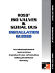
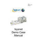
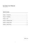
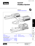
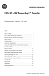
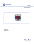
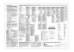
Installation & Service Instructions
A10312
Serial Bus 32 Point Valve Driver,
Series A (RPSSV32A)
ISSUED: August, 2007
Supersedes: None
! WARNING
To avoid unpredictable system behavior that can cause personal injury
and property damage:
• Disconnect electrical supply (when necessary) before installation,
servicing, or conversion.
• Disconnect air supply and depressurize all air lines connected to this
product before installation, servicing, or conversion.
• Operate within the manufacturer’s specified pressure, temperature,
and other conditions listed in these instructions.
• Medium must be moisture-free if ambient temperature is below
freezing.
• Service according to procedures listed in these instructions.
• Installation, service, and conversion of these products must be
performed by knowledgeable personnel who understand how
pneumatic products are to be applied.
• After installation, servicing, or conversion, air and electrical supplies
(when necessary) should be connected and the product tested for
proper function and leakage. If audible leakage is present, or the
product does not operate properly, do not put into use.
• Warnings and specifications on the product should not be covered by
paint, etc. If masking is not possible, contact your local representative
for replacement labels.
Introduction
Follow these instructions when installing, operating, or servicing the
product.
Serial Bus 32 Point Valve Driver, Series A
(RPSSV32A)
The sealed IP67 housing of these modules requires no enclosure.
(Note that environmental requirements other than IP67 may require
an additional appropriate housing.) The RPSSV32A module is shown
below.
The RPSSV32A valve driver module provides an interface between the
serial bus system and the valve assembly. This module will always be
the last module on the serial bus. It controls 32 digital outputs at 24VDC.
Depending on valve selection, it can control up to 32 single solenoid
valves or 16 double solenoid valves.
RPSSV32A
S
A
V32
PSS
S
O
R
Mod
lt
Fau
Net
Safety Guide
For more complete information on recommended application guidelines,
see the Installation Safety Guidelines section of Bulletin 600 (Form
A10309) or you can download the Installation Safety Guidelines at:
www.rosscontrols.com/rosslit.htm.
Outputs
1- 24
Connector
Outputs
25- 32
Connector
! WARNING
FAILURE OR IMPROPER SELECTION OR IMPROPER USE OF THE
PRODUCTS AND/OR SYSTEMS DESCRIBED HEREIN OR RELATED
ITEMS CAN CAUSE DEATH, PERSONAL INJURY AND PROPERTY
DAMAGE.
This document and other information from ROSS CONTROLS, its
subsidiaries and authorized distributors provide product and/or system
options for further investigation by users having technical expertise. It
is important that you analyze all aspects of your application, including
consequences of any failure and review the information concerning the
product or systems in the current product catalog. Due to the variety of
operating conditions and applications for these products or systems, the
user, through its own analysis and testing, is solely responsible for making
the final selection of the products and systems and assuring that all
performance, safety and warning requirements of the application are met.
The products described herein, including without limitation, product features,
specifications, designs, availability and pricing, are subject to change by
ROSS CONTROLS and its subsidiaries at any time without notice.
EXTRA COPIES OF THESE INSTRUCTIONS ARE AVAILABLE FOR INCLUSION
IN EQUIPMENT / MAINTENANCE MANUALS THAT UTILIZE THESE PRODUCTS.
CONTACT YOUR LOCAL REPRESENTATIVE.
Serial Bus 32 Point Valve Driver, Series A (RPSSV32A)
Important User Information
ATTENTION
Solid state equipment has operational characteristics differing from
those of electromechanical equipment. Safety Guidelines for the
Application, Installation and Maintenance of Solid State Controls
(Form #A10325) (available online at www.rosscontrols.com/rosslit.
htm), describes some important differences between solid state
equipment and hard-wired electromechanical devices. Because
of these differences, and also because of the wide variety of uses
for solid state equipment, all persons responsible for applying this
equipment must satisfy themselves that each intended application of
this equipment is acceptable.
In no event will ROSS CONTROLS® be responsible or liable for
indirect or consequential damages to persons or property resulting
from the use or application of this equipment.
The examples and diagrams in this manual are included solely
for illustrative purposes. Because of the many variables and
requirements associated with any particular installation, ROSS
CONTROLS cannot assume responsibility or liability for actual use
based on the examples and diagrams.
No patent liability is assumed by ROSS CONTROLS with respect
to use of information, circuits, equipment, or software described in
this manual.
Reproduction of the contents of this manual, in whole or in part, without
written permission of ROSS CONTROLS is prohibited.
Throughout this manual we use notes to make you aware of safety
considerations.
WARNING
!
Identifies information about practices or
circumstances that can cause an explosion in
a hazardous environment, which may lead to
personal injury or death, property damage, or
economic loss.
IMPORTANT
Identifies information that is critical for successful
application and understanding of the product.
ATTENTION
Identifies information about practices or
circumstances that can lead to personal injury
or death, property damage, or economic loss.
Attentions help you:
• Identify a Hazard
• Avoid a Hazard
• Recognize the Consequence
!
SHOCK HAZARD Labels may be located on or inside the
equipment to alert people that dangerous
voltage may be present.
BURN HAZARD
Labels may be located on or inside the
equipment to alert people that surfaces may be
dangerous temperatures.
!
Environment and Enclosure
This equipment is intended for use in overvoltage Category
II applications (as defined in IEC publication 60664-1), at
altitudes up to 2000 meters without derating. This equipment
is considered Group 1, Class A industrial equipment according
to IEC/CISPR Publication 11. Without appropriate precautions,
there may be potential difficulties ensuring electromagnetic
compatibility in other environments due to conducted as well as
radiated disturbance. This equipment is supplied as “enclosed”
equipment. It should not require additional system enclosure
when used in locations consistent with the enclosure type
ratings stated in the Specifications section of this publication.
Subsequent sections of this publication may contain additional
information regarding specific enclosure type ratings, beyond
what this product provides, that are required to comply with
certain product safety certifications.
NOTE: See NEMA Standards publication 250 and IEC
publication 60529, as applicable, for explanations of the
degrees of protection provided by different types of enclosure.
Also, see the appropriate sections in this publication, as well
as the publication A10324 (“Industrial Automation Wiring and
Grounding Guidelines”), for additional installation requirements
pertaining to this equipment.
ATTENTION
!
Preventing Electrostatic Discharge
This equipment is sensitive to electrostatic discharge, which
can cause internal damage and affect normal operation. Follow
these guidelines when you handle this equipment:
•Touch a grounded object to discharge potential static.
•Wear an approved grounding wrist strap.
•Do not touch connectors or pins on component boards.
•Do not touch circuit components inside the equipment.
•If available, use a static-safe workstation.
•When not in use, store the equipment in appropriate staticsafe packaging.
© 2007 ROSS CONTROLS®. All Rights Reserved.
Serial Bus 32 Point Valve Driver, Series A (RPSSV32A)
Mount the I/O Base
To mount the I/O base on a wall or panel, use the screw holes
provided in the base.
IMPORTANT
The I/O module must be mounted on a grounded metal mounting
plate or other conductive surface.
*Depending on the type and number of manifolds, this dimension
may vary. Consult Ross for specific information.
A mounting illustration for the base with an adapter is shown below.
1.9
(47.2)
2.0
(50)
0.87
(22)
2.0
(50)
3.13
(79.4)
5.98*
(151.9)
Adapter
2.39
(60.7)
4.02
(102)
4.32
(109.8)
1.81
(46)
Inches
(mm)
3.02
(76.6)
Drill and Tap
for M4 Screw
5.39
(137.0)
Install the 32 Point Valve Driver
Drill and Tap
for M6 Screw
To Install the 32 Point Valve Driver, Proceed as Follows:
1.Assemble the valve driver to the manifold interface plate using
four M4 screws, torqued 11 to 13 in. lbs.
2.Plug the 32 point valve driver onto the previous mounting base
or communication adapter.
Wire the 32 Point Valve Driver
Following are wiring instructions for the 32 point valve driver.
Use the appropriate harness assembly based on your manifold
wiring/interconnect system.
Harness Assembly Kit Numbers
Series W66, Size 0
Series W66, Size 00
Series W65, Size 1
Series W65, Size 2
Series W65, Size 3
1 to 24 Outputs
25 to 32 Outputs
RPS5624P
RPS5632P
RPS4024P
RPS4032P
Plug the 2X15 connector into the valve driver module for 1-24 outputs.
If you have more than 24 outputs, plug the 2X5 connector into the
valve driver module for 25-32 outputs.
Outputs
1- 24
Connector
Outputs
25- 32
Connector
Plug the 2X10 and 1X10 connectors into the interconnect board in
the valve manifold.
EDS File Requirements
The EDS file is available online at www.rosscontrols.com/rosslit.htm
ATTENTION
!
Make sure all four screws are securely tightened to properly seal
the connections against leaks and maintain IP67 requirements.
www.rosscontrols.com
Serial Bus 32 Point Valve Driver, Series A (RPSSV32A)
Communicate With Your Module
I/O messages are sent to (consumed) and received from (produced)
the I/O modules. These messages are mapped into the processor’s
memory. The 32 point valve driver produces 1 byte of input data
(scanner Rx - status), and consumes 1 byte of I/O data (scanner
Tx).
Default Data Map for the 32 Point Valve Driver
RPSSV32A
Message Size: 1 Byte
Byte
Bit 7 Bit 6 Bit 5 Bit 4 Bit 3 Bit 2 Bit 1 Bit 0
Produce 0 OutputOutput OutputOutput OutputOutputOutput Output
7
6
5
4
3
2
1
0
Produce 1 OutputOutput OutputOutput OutputOutputOutput Output
15
14
13
12
11
10
9
8
Produce 2 OutputOutput OutputOutput OutputOutputOutput Output
23
22
21
20
19
18
17
16
Produce 3 OutputOutput OutputOutput OutputOutputOutput Output
31
30
29
28
27
26
25
24
Produce 4 Fault Fault Fault Fault Fault Fault Fault Fault
28-31 24-27 20-23 16-19 12-15 8-11 4-7
0-3
Setup the 32 Point Valve Driver in ControlNet
Step 1: Load 32 Point Valve Driver EDS file to RSLinx
•Download EDS file from www.rosscontrols.com/rosslit.htm
•On your computer, follow Start➔Rockwell Software➔RSLinx
Tools➔EDS Hardware Installation Tool to load the EDS file to
RSLinx
Step 2: Add Controller and Communication Module to the
RSLogix 5000 I/O Configuration
•Add a controller and a communication module (Serial Bus
RPSSCCNA or Rockwell 1738-ACNR) to I/O configuration. Reference
pages 4-1 through 4-7 of Rockwell publication 1734-UM008 (follow
www.rockwell.com➔Support➔Support Overview➔Online
manuals and literature➔I/O➔1734 POINT and 1734D POINT
Block I/O and find POINT I/O ControlNet Adapter User Manual) for
a similar setup procedure.
Step 3: Add 32 Point Valve Driver to RSLogix 5000
I/O Configuration.
If your RSLogic 5000 is Version 15.X or greater:
•Highlight the RPSSCCNA under I/O configuration, right click and
select New Module.
•Choose the RPSSV32A module from the list of Parker modules.
Consume 0 OutputOutput OutputOutput OutputOutputOutput Output
7
6
5
4
3
2
1
0
Consume 1 OutputOutput OutputOutput OutputOutputOutput Output
15
14
13
12
11
10
9
8
Consume 2 OutputOutput OutputOutput OutputOutputOutput Output
23
22
21
20
19
18
17
16
Consume 3 OutputOutput OutputOutput OutputOutputOutput Output
31
30
29
28
27
26
25
24
•Enter a name (optional) and click OK.
Setup the 32 Point Valve Driver in DeviceNet
Step 1: Load 32 Point Valve Driver EDS file to RSLinx
•Download EDS file from www.rosscontrols.com/rosslit.htm
•On your computer, follow Start➔Rockwell Software➔RSLinx
Tools➔EDS Hardware Installation Tool to load the EDS file to
RSLinx
Step 2: Configure the DeviceNet Scanner Subnet
•Reference Chapter 4 of the Serial Bus DeviceNet Adapters User
Manual Bulletin 601 (Form #A10311) for detailed information. Make
sure to add RPSSV32A to the DeviceNet Adapter’s scanlist.
Step 3: Add the Serial Bus DeviceNet Adapter to the DeviceNet
Scanner’s Scanlist
•Reference Chapter 5 of the Serial Bus DeviceNet Adapters User
Manual Bulletin 601 (Form #A10311) for detailed information.
Step 4: Use 32 Point Valve Driver in RSLogix 5000
•Access RPSSV32A data via DeviceNet Scanner in the ladder logic
program.
Notice that the 32 Point Valve Drive Module is now under I/O
Configuration.
© 2007 ROSS CONTROLS®. All Rights Reserved.
Serial Bus 32 Point Valve Driver, Series A (RPSSV32A)
If your RSLogic 5000 is Version 13.X:
•Highlight the 1738-ACNR under I/O configuration, right click and
select New Module.
•Choose the Generic 1738 module from the list of Allen-Bradley
modules.
Setup the 32 Point Valve Driver in EtherNet/IP
Step 1: Load 32 Point Valve Driver EDS file to RSLinx
•Download EDS file from www.rosscontrols.com/rosslit.htm
•On your computer, follow Start➔Rockwell Software➔RSLinx
Tools➔EDS Hardware Installation Tool to load the EDS file to
RSLinx
Step 2: Set IP Address for EtherNet/IP Scanner and Adapter
•Set IP address using Rockwell BootP/DHCP utility for
EtherNet/IP scanner and PSSCENA or 1738-AENT adapter.
Reference pages 3-7 through 3-10 of Rockwell publication
1734-UM011 (follow www.rockwell.com➔Support➔Support
Overview➔Online manuals and literature➔I/O➔1734 POINT and
1734D POINT Block I/O and find POINT I/O Ethernet Adapter User
Manual) for similar information.
Step 3: Add EtherNet/IP Scanner and Adapter to RSLogix
5000 I/O configuration.
•Add EtherNet/IP scanner and PSSCENA or 1738-AENT adapter to
I/O configuration. Reference pages 4-4 to 4-8 of Rockwell publication
1734-UM011 for similar information.
•Enter a name (optional), an appropriate slot number and the
connection parameters as shown in this screen capture.
Step 4: Add 32 Point Valve Driver to RSLogix 5000
I/O Configuration.
If your RSLogic 5000 is Version 15.X or greater:
•Highlight the PSSCENA under I/O configuration, right click and select
New Module.
•Choose the RPSSV32A module from the list of Ross modules.
•Choose Next to set RPI.
•Choose Finish. Notice that the 32 Point Valve Driver Module is now
under the I/O configuration.
Step 4: Download the Program to the Controller and
Configure the RPSSCCNA or 1738-ACNR Adapter.
•Reference pages 4-11 through 4-15 of Rockwell publication 1734UM008 for similar setup procedure.
•Enter a name (optional) and click OK.
Step 5: Schedule I/O Module Connections
•Reference pages 4-15 through 4-19 of Rockwell publication 1734UM008 for similar setup procedure.
Step 6: Access Module Data via the RPSSCCNA or 1738-ACNR
Adapter.
•Make sure the 32 outputs of RPSSV32A appear in Controller Tags.
Use the information in the ladder logic program to access module
data.
•Reference pages 4-19 through 4-22 of Rockwell publication 1734UM008 for similar information.
Notice that the 32 Point Valve Drive Module is now under I/O
Configuration.
www.rosscontrols.com
Serial Bus 32 Point Valve Driver, Series A (RPSSV32A)
If your RSLogic 5000 is Version 13.X:
•Highlight the 1738-AENT under I/O configuration, right click and
select New Module.
•Choose the Generic 1738 module from the list of Allen-Bradley
modules.
Setup the 32 Point Valve Driver in Profibus
Step 1: Configure Valve Driver Module in SST Profibus
Configuration Utility
Note: SST-PFB-CLX is used here for example. For different
Profibus scanners, refer to appropriate documentation for setup
information.
•Download GSD file from www.rosscontrols.com/rosslit.htm
•In SST Profibus Configuration Utility, follow Library➔Add GSD to
load the GSD file to SST Profibus.
•In SST Profibus Configuration Utility, follow Browse➔Search for
devices to load the GSD file to SST Profibus
•Right click on the found device, follow GSD files and click on
appropriate GSD for RPSSV32A.
•Add RPSSV32A as slave to SST-PFB-CLX master.
•Detailed information can be found in the SST-PFB-CLX User Guide
(Ver. 1.4 715-0022), which is available on www.woodhead.com.
Step 2: Add SST Profibus Scanner in RSLogix 5000
I/O Configuration
•Add SST-PFB-CLX scanner I/O configuration. Reference pages 36
to 39 of the SST-PFB-CLX User Guide, for detailed information.
•Notice that the SST-PFB-CLX scanner is now under the I/O
configuration.
•Enter a name (optional), an appropriate slot number and the
connection parameters as shown in this screen capture.
Step 3: Access Module Data via the SST-PFB-CLX Scanner
and Create Ladder Program.
•Reference Chapter 7 of the SST-PFB-CLX User Guide for addressing
information.
•Choose Next to set RPI.
•Choose Finish. Notice that the 32 Point Valve Driver Module is now
under the I/O configuration.
Step 5: Access Module Data via the RPSSCENA or 1738-AENT
Adapter and Create Ladder Program.
•Make sure the 32 outputs of RPSSV32A appear in Controller Tags.
Use the information in the ladder logic program to access module
data.
•Reference pages 4-13 through 4-14 of Rockwell publication 1734UM011 for similar information.
Step 6: Download the Program to the Controller
•Reference pages 4-13 through 4-14 of Rockwell publication 1734UM011 for similar information.
© 2007 ROSS CONTROLS®. All Rights Reserved.
Serial Bus 32 Point Valve Driver, Series A (RPSSV32A)
Troubleshoot With the Indicators
RPSSV32A
ROSS
RPSSV32A
Module Status
Indicator
Mod
Net
Fault
Network Status
Indicator
Output Fault Status
Indicator
Indication
Probable Cause
Module Status
Off
No power applied to device
Green
Device operating normally
Flashing Green
Device needs commissioning due to missing, incomplete, or incorrect configuration
Flashing Red
Recoverable fault
Red
Unrecoverable fault - may require device replacement
Flashing Red/Green
Device is in self-test
Indication
Probable Cause
Network Status
Off
Device is not on line:
- Device has not completed dup_MAC-id test.
- Device not powered - check module status indicator.
Flashing Green
Device is on line but has no connections in the established state.
Green
Device is on line and has connections in the established state.
Flashing Red
One or more I/O connections in timed-out state.
Red
Critical link failure - failed communication device. Device detected error that prevents it from
communicating on the network.
Flashing Red/Green
Communication faulted device - the device has detected a network access error and is in
communication faulted state. Device has received and accepted an Identity Communication
Faulted Request - long protocol message.
Indication
Probable Cause
Output Fault Status
Off
Outputs operating normally
Red
Over current, short circuit or over temperature detected on one or more outputs. (On-State only)
www.rosscontrols.com
Serial Bus 32 Point Valve Driver, Series A (RPSSV32A)
Specifications – Following are specifications for the 32 point valve driver.
32 Point Valve Driver
Outputs per Module
32, sourcing
Voltage Drop, On-State Output, Maximum
0.2VDC
Voltage, Off-State Output, Maximum
28.8VDC
Voltage, On-State Output,
Maximum
28.8VDC
Minimum
10VDC
Nominal
24VDC
Output Current Rating
200 mA per channel, not to exceed 6.0 A per module
Output Surge Current, Maximum
0.5 A for 10 ms, repeatable every 3 seconds
Current Leakage, Off-State Output, Maximum
0.1 mA
Current, On-State Output Minimum
200 mA per channel
Output Delay Time OFF to ON, Maximum1
0.1 ms
Output Delay Time, ON to OFF, Maximum1
0.1 ms
External DC Power Supply Voltage Range
10 to 28.8VDC
External DC Power Supply Voltage Nominal
24VDC
General Specifications
LED Indicators
1 output status
1 green/red network status, logic side
1 green/red module status, logic side
PointBus Current, Maximum
75 mA @ 5VDC
Operating Temperature
IEC 60068-2-1 (Test Ad, Operating Cold),
IEC 60068-2-2 (Test Bd, Operating Dry Heat),
IEC 60068-2-14 (Test Nb, Operating Thermal Shock):
-20 to 60°C (-4 to 140°F)
Storage Temperature
IEC 60068-2-1 (Test Ab, Un-packaged Non-operating Cold),
IEC 60068-2-2 (Test Bb, Un-packaged Non-operating Dry Heat),
-40 to 85°C (-40 to 185°F)
Relative Humidity
IEC 60068-2-30 (Test Db, Un-packaged Non-operating Damp Heat):
5 to 95% non-condensing
Shock
IEC60068-2-27 (Test Ea, Unpackaged Shock):
Operating 30g
Non-operating 50g
Vibration
IEC60068-2-6 (Test Fc, Operating):
5g @ 10 to 500Hz
ESD Immunity
IEC 61000-4-2:
6kV contact discharges
8kV air discharges
Radiated RF Immunity
IEC 61000-4-3:
10V/m with 1kHz sine-wave 80%AM from 30MHz to 2000MHz
10V/m with 200Hz 50% Pulse 100%AM at 900Mhz
10V/m with 200Hz 50% Pulse 100%AM at 1890Mhz
EFT/B Immunity
IEC 61000-4-4:
±3kV at 5kHz on signal ports
Surge Transient Immunity
IEC 61000-4-5:
±1kV line-line(DM) and ±2kV line-earth(CM) on signal ports
Conducted RF Immunity
IEC 61000-4-6:
10Vrms with 1kHz sine-wave 80%AM from 150kHz to 80MHz
Emissions
CSPR 11:
Group 1, Class A
Enclosure Type Rating
Meets IP65/66/67 (when marked)
Mounting Base Screw Torque
#8 screw, 7.5 in. lbs. in Aluminum, 16 in. lbs. in Steel
Wiring Category2
1 - on signal ports
Certifications:
c-UL-us UL Listed Industrial Control Equipment,
(when product is marked)
certified for US and Canada
CE
European Union 89/336/EEC EMC Directive,
compliant with:
EN 61000-6-4; Industrial Emissions
EN 50082-2; Industrial Immunity
EN 61326; Meas./Control/Lab., Industrial Requirements
EN 61000-6-2; Industrial Immunity
C- Tick Australian Radiocommunications Act, compliant with:
AS/NZS CISPR 11; Industrial Emissions
1. OFF to ON or ON to OFF delay is time from a valid output “on” or “off” signal to output energization or de-energization.
2. Use this Conductor Category information for planning conductor routing. Refer to Publication A10324, “Industrial Automation Wiring and Grounding Guidelines”.
Printed in U.S.A -0807
© Copyright 2007, ROSS CONTROLS®. All Rights Reserved.
Form A10312