1
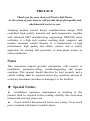
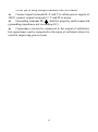
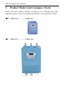
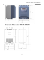
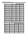
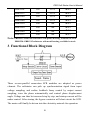
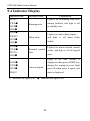
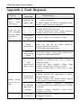
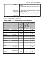
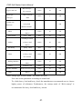
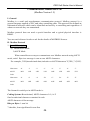
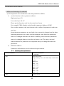
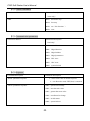
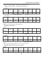
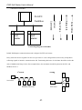
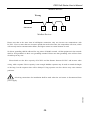
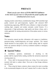
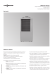
PROSTAR SOFTSTARTER PRR1000 SERIES 15~315KW INSTRUCTION MANUAL PRR Soft Starter User’s Manual PREFACE Thank you for your choice of Prostar Soft Starter. As the return of your trust we will provide the perfect quality and wholehearted service to you. Adopting modern control theory, modularization design, DSP controlled high quality material and parts/components, together with advanced SMT manufacturing engineering, PRR1000 series softstarter is a high tech product combing digit, computer and modern automatic control theories. It is characteristic of high performance, high quality and skinny volume, and is widely applicable for starting and protection of three-phase motors in various industries. Notes This instruction manual provides information with respects to installation, parameter-setting, trouble-diagnosing and proper operation. This manual should therefore be kept properly and a careful reading shall be required before any operation attempt to avoid any accidental casualties or damage(s) to the facilities. ★ Special Notice: ▲ Installation, operation, maintenance or checking to this product shall be required before reading carefully this instruction manual and ensuring proper use. ▲ Power shall be disconnected before any wiring. Never touch power terminal with hand or conduct object. ·2· PRR Soft Starter User’s Manual Never put or drop foreign substance into soft starter. ▲ Connect input terminals R, S and T to urban power supply of 380V; connect output terminals U, V and W to motor. ▲ Grounding terminal PE shall be properly earth connected (grounding impedance not exceeding 4Ω). ▲ Capacitance can not be connected to the output of softstarter, but capacitance can be connected to the input of softstater when it is used for improving power factor. ·3· CONTENTS 1. Product Model and Consignee Check…………………… 1 2. Installation ……………………………………………… 3 3. Functional Block Diagram……………………………… 6 4. Technical Parameters…………………………………… 7 5. Wiring…………………………………………………… 8 6. Setting………………………………………………… 12 7. Function Chart ……………………………………… 15 8. Function in Details…………………………………… 16 9. State Indication ……………………………………… Appendix 1. Maintenance………………………………… 22 24 Appendix 2. Fault Diagnosis……………………………… 25 Appendix 3. Applications………………………………… 26 Appendix 4. Modbus communication …………………… 28 PRR Soft Starter User’s Manual 1. Product Model and Consignee Check Please check the product carefully according to the following steps after unpacking, please contact the supplier immediately if any problem is found. PRR1015————PRR1055 PRR1075————PRR1200 ·1· PRR Soft Starter User’s Manual PRR1220————PRR1315 Standards for Product Design GB/T 12668.2 2002 Standard of .rated value for low voltage AC frequency conversion electric drive system. GB/T 12668.3 2003 Standard and testing method of electromagnetism compatibility. ·2· PRR Soft Starter User’s Manual 1.1 Nameplate Check Model Illustration: PRR 1 □□□ Adaptive motor power(KW) 1000 Series Bypass Model Prostar Softstarter 1.2 Product Check-up Product check- up is advised to be carried out to make sure whether damage(s) revived during transportation, such as depressed shell, distortion, loose connection with wiring or connected parts. 1.3 Unpacking Check-up Each softstarter has certificate of quality and user’s manual. Please make sure whether the certificate and the manual are intact and conform to each other. 2. Installation For keeping a good product capability, the softstarter must be installed vertically. Installation space should strictly obey the following requirements. Good ventilation should be available to the installation environment, which should avoid direct sunlight for indoor installation. Environment temperature: -10℃~+50℃ Relative humidity: ≤95% (20℃±5℃) Environment conditions: Free from flammable gas, explosive gas and corrosive gas, free from electric dust, to be installed indoors with good ventilation. Vibration below 0.5G If the altitude is above 2000m, the capacity should be decreased accordingly for application. Structure Dimension: 15KW-55KW ·3· PRR Soft Starter User’s Manual Structure Dimension: 75KW-315KW ·4· PRR Soft Starter User’s Manual External Dimension(Unit:mm) Model A(High) B(Wide) C(Thick)) PRR1015(15KW) 250 153 162 PRR1022(22KW) 250 153 162 PRR1030(30KW) 250 153 162 PRR1037(37KW) 250 153 162 PRR1045(45KW) 250 153 162 PRR1055(55KW) 250 153 162 PRR1075(75KW) 510 260 194 PRR1090(90KW) 510 260 194 PRR1110(110KW) 510 260 194 PRR1132(132KW) 510 260 194 PRR1160(160KW) 510 260 194 PRR1200(200KW) 510 260 194 PRR1220(220KW) 590 360 255 PRR1250(250KW) 590 360 255 PRR1280(280KW) 590 360 255 PRR1315(315KW) 590 360 255 Installation Dimension(Unit: mm) Model E(High) F(Wide) Φ(Hole Dia) PRR1015 219 140 Φ6 PRR1022 219 140 Φ6 PRR1030 219 140 Φ6 PRR1037 219 140 Φ6 PRR1045 219 140 Φ6 PRR1055 219 140 Φ6 PRR1075 389 232.5 Φ8.5 PRR1090 389 232.5 Φ8.5 ·5· PRR Soft Starter User’s Manual PRR1110 389 232.5 Φ8.5 PRR1132 389 232.5 Φ8.5 PRR1160 389 232.5 Φ8.5 PRR1200 389 232.5 Φ8.5 PRR1220 560 300 Φ8.5 PRR1250 560 300 Φ8.5 PRR1280 560 300 Φ8.5 PRR1315 560 300 Φ8.5 Note: PRR1015--PRR1200 softstarter with plastic housing, available in stock. PRR1220--PRR1315 softstarter with metal housing, available in stock. 3. Functional Block Diagram Three reverse-parallel connection SCR modules are adopted as power element. The softstarter can pick up synchronization signal from input voltage sampling, and realize feedback fuzzy control by output current sampling, trace the phase automatically and control phase displacement angle. Voltage can thus be increased step by step, and startup current will be under control. After startup, the bypass contactor will short-circuit the SCR. The motor will finally be driven into the electricity network for operation. ·6· PRR Soft Starter User’s Manual 4. Technical Parameters Control power supply AC 380V±20%, 50/60Hz 3-Phase power supply AC 380V±20%, 50/60Hz Nominal current Motor power Applicable motor Startup mode Stop mode Relay output 30A~630A, totally 16 kinds of rated currents 15~315KW(rated voltage 380V) Common squirrel cage type asynchronism motor Voltage kick soft startup; current limiting startup (150~400%, adjustable); voltage ramp startup (1~180seconds, adjustable) Free stop; soft stop (1~180seconds , adjustable) Delay running output; fault output; full voltage output (by pass) [contact dot: 5A, 250VAC] Startup frequency for frequent or infrequent startup; Advise: not exceeding ten times per hour Protection function Phase loss of input, over-load, short circuit, over-heating, and etc. Safety degree IP20 Cooling mode Cooling naturally Installation mode Hanging mode Environment temperature:-10℃~+50℃ Relative humidity:≤95%(20℃±5℃) Free from flammable gas, explosive gas and Environment conditions corrosive gas, free from electric dust, to be installed indoors with good ventilation Vibration below 0.5G If the altitude is above 2000m, the capacity should be decreased accordingly for application. 5.Wiring ·7· D D PRR Soft Starter User’s Manual 5.1 Terminal Function C C Y1 Y2 Y3 T1 T2 T3 30A 30B 30C CM RUN STOP BX RST PE 1 2 3 4 5 6 7 8 9 10 11 12 13 14 15 B A B Terminal Number Technical Title Terminal Name 1 A Description Size A4 Date: File: 2 Number 29-Sep-2004 F:\HGY的 文 档 \ Revision \ 3 Parameters Sheet of .Ddb Drawn By: 4 1 Start-delay Signal Y1: Middle terminal AC250V5A 2 Start-delay Signal Y2-Y1Normal close AC250V5A 3 Start-delay Signal Y3-Y1Normal open AC250V5A 4 Bypass Signal T1: Middle terminal AC250V5A 5 Bypass Signal T2-T1Normal close AC250V5A 6 Bypass Signal T3-T1Normal open AC250V5A 7 Fault Signal 30A: Middle terminal AC250V5A 8 Fault Signal 30B-30A Normal close AC250V5A 9 Fault Signal 30C-30A Normal open AC250V5A 10 Common Terminal CM(External Common Terminal) 11 Startup Signal RUN-CM effective turn on 12 Stop Signal STOP-CM effective turn on 13 Free stop Signal BX-CM effective turn on 14 Reset Signal RST-CM effective turn on 15 Function Ground -Terminal PE—Ground ·8· PRR Soft Starter User’s Manual 5.2 Basic Wiring Diagram R, S, T terminals of softstarter are input terminals while U, V, W are output terminals. QF-auto air breaker, KM-contactor, RJ-over heating protection relay, RD1-fuse, L11—N is connected to 220V. ·9· PRR Soft Starter User’s Manual 5.3 Recommended Wiring Diagram !PE Grounding wire should be as short as possible, and should be connected to the nearest grounding point, better on the installation board against the softstarter. Installation board should also be grounded. Controlling Loop: User can select to use bypass contactor. It can be switched to bypass circuit running automatically. To select this operation mode, an AC contactor should be fixed (to be ordered separately) ·10· PRR Soft Starter User’s Manual 5.4 Optional Parts Adaptable Motor(KW) Model Rated Contactor Model Wiring Current(A) (optional) (MM2) 15 PRR1015 30 CJX4-50 10 22 PRR1022 45 CJX4-50 10 30 PRR1030 60 CJX4-80 16 37 PRR1037 76 CJX4-80 16 45 PRR1045 90 CJX4-95 25 55 PRR1055 110 CJX4-115F 25 75 PRR1075 150 CJX4-150F 35 90 PRR1090 180 CJX4-185F 35 110 PRR1110 218 CJX4-225F 50 132 PRR1132 260 CJX4-265F 60 160 PRR1160 320 CJX4-330F 75 200 PRR1200 400 CJX4-500F 90 220 PRR1220 440 CJX4-500F 90 250 PRR1250 500 CJX4-630F 150 280 PRR1280 560 CJX4-630F 150 315 PRR1315 630 CJX4-630F 150 ·11· PRR Soft Starter User’s Manual 6.Setting Keypad Panel Note Keys Name of Keys The following is the operation instruction of keypad panel. Fig 1-1 Mode set ▲ ▼ run Stop/Reset keypad panel “mode” key Control box displays function code “PR××”. The current and “stop” key switch to each other. “set” key To be used with “mode” key. Under the “PR××” display state, press “set” key, the control box will display the corresponding value of function code. Press “up” and “down” key to change its value, and then press “set” to save the changed value. “up” key Under “PR××” display state, press “up”, “down” key to select other function code. After enter the function code, “down” they are used to change the value of the function code. key “run” Press“run” key for startup. key “stop/res et” key Under any state, press “stop/reset” key, it will have priority to be valid. Press twice for free stop of the softstarter. And it also can reset the softstarter when malfunction happens. ·12· PRR Soft Starter User’s Manual Special Display Content and Interpretation Display Items Interpretation -PR- Show reset process; under single control mode, it displays such content after reset normally; RUN startup state STOP Stop state OUT Run state SST Soft-stop state Count Down Delay state Set the Starter through Keypad Main adjustable parameters:Initial voltage Startup time Stop time Startup current Startup mode: Voltage ramp soft startup Current limiting soft startup Kick soft startup Stop mode: voltage ramp soft stop mode Free stop mode Soft Startup/Soft Stop Voltage (Current) Feature Curve ·13· PRR Soft Starter User’s Manual 6.1 Initial Voltage Setting (U0) Initial voltage for startup (0--50%)Ue, stepless adjustable. Initial voltage for kick startup, voltage (20%-100%) Ue, stepless adjustable。 Select 100% as full voltage startup, at present the softstarter works as a switch without contact. 6.2 Startup Ramp Time Setting Ramp ascending time: 1-180S, adjustable。 6.3 Stop Ramp Time Setting Ramp descending time:1-180S, adjustable。 6.4 Startup Current Limit Startup current (1.5~4) Ie : stepless adjustable. (with the data set, the biggest startup current will be limited in this range) The above parameters should be set when the starter is not working! Under the startup, soft-stop and full-voltage working state, all the parameter-settings will not be effective. All the technical parameters of softstarter are effective when the environment temperature is below 45 ℃ . If the environment temperature is from 45℃ to 60℃, the rated power should be decreased by a power-level. ·14· PRR Soft Starter User’s Manual 7. Softstarter Function Chart Function No. Function Explanation Data Explanation Mfr Value 1 Startup mode 0 keypad control 1 External terminal control 0 Voltage ramp startup 1 Current limit startup 2 Kick startup PR02 Startup delay time 0-600S 0S PR03 Stop mode 0 Free stop PR04 Torque compensation 0-50% Rated voltage 5% PR05 Kick voltage 20-100%Rated voltage 50% PR06 Kick time 1-60S 2S PR07 Ramp ascending time 1-180S 20S PR08 Ramp descending time 1-180S 20S PR09 Startup current limit 150-400% Rated current 400% PR10 Startup time interval 1-3600S 240S PR11 Data initialization 0 No action 1Action (manufacturer value restored) 0 PR12 Fault memory 1 Present fault PR13 Fault memory 2 previous fault PR14 Fault memory 3 Previous two faults PR15 Fault memory elimination 0 No Action PR16 Overload protection time 1-180S 60S PR17 OL protect value 100-400% rated current 300 PR18 Stop bits 0 one 1 two 0 PR19 Parity check 0 Odd 0 PR20 Communication baud rate 0: 1200 bit 1: 2400 bit 2: 4800 bit 3: 9600 bit PR00 Control mode PR01 1 Soft stop 1 action 1 Even 2 No check 1 0 0 2 4: 19200 bit PR21 Communication Address 1-127: softstarter address ·15· 1 PRR Soft Starter User’s Manual PR22 Selection of ASCII mode 0 ASCII mode 0 and RTU mode 1 RTU mode PR23 Motor power 1-315KW 22KW PR24 Reserved 0~9999 0 8. Function in Details PR00 Control mode 0 Keypad control 1 external terminal control 1 Control mode selection can be operated directly through the panel keypad, and can also be done by external terminal control. The manufacturer value is 1. PR01 Startup mode 0 Voltage ramp startup 1 Current limit startup 2 Kick startup 1 You can start by selecting one of the following three modes: 0 Voltage ramp startup, 1 current limit startup, 2 kick startup, manufacturer value is 1 ΔVoltage ramp startup Set PR01 to 0, and set ramp startup time t (PR07) and torque compensation voltage (PR04) U0, the motor will start along with the increasing input voltage, and the speed will accelerate accordingly till its top speed, as shown in Figure (1). Voltage Ramp Startup Feature Curve, Figure (1) ·16· PRR Soft Starter User’s Manual ΔCurrent limit startup Set PR01 to 1 and set startup current limit percent Is(PR09)and Torque compensation voltage (PR04). The current of the motor will increase until the voltage ramp reaches Is, then it will stop, and the speed will accelerate to its full speed. After that, the current will decrease to below the rated current Ie, as shown in Figure (2): 1 2 3 4 D D I C C Is Ie B B T Current Limit Startup Feature Curve (2) Title A Size A4 Date: File: A Number 18-Sep-2004 F:\HGY \ Revision \ .ddb Sheet of Drawn By: 4 ΔKick startup Set PR01 to 2, and set ramp start time t(PR07) and torque compensation (PR04), kick time t(PR06). The motor will start rapidly along with the increasing voltage, then the voltage will increase in a ramp way, and the speed will accelerate to its full speed. It is better for startup motor with big inertia, as shown in Figure (3): 1 2 3 Kick Startup Feature Curve (3) ·17· PRR Soft Starter User’s Manual PR02 Startup delay time 0-600S 0S Startup delay time is set for startup preparation, and the motor will not start in this interval. Count down mode is used for display, and the time can be set from 0 to 600 seconds. And it will output a normal open –normal close contact dot signal. By applying the signal, a warning signal may be affected for safety attention! The manufacturer value is set to 0S PR03 Free stop 0 Free stop 1 Soft stop 0 You can stop by selecting two modes: 0 free stop 1 soft stop. The manufacturer value is set to 0. Free stop means that the voltage of softstarter will reduce directly from Ue to 0V,and the motor will run with inertia till its stop, as shown in Figure (4): 1 2 3 4 D D U Ue C C B B T Title A Size 1 Free Stop Feature Curve Figure (4) 2 A Number Revision A4 Date: File: 3 18-Sep-2004 F:\HGY \ \ .ddb Sheet of Drawn By: 4 Soft stop means that the voltage of starter will reduce gradually from Ue to 0V when the voltage drops. The soft stop can help resist “water hammer domino effect ”, as shown in Figure (5): Soft Stop Feature Curve ·18· Figure (5) PRR Soft Starter User’s Manual PR04 Torque compensation 0-50% rated voltage 5% Torque compensation means to adjust the torque produced by initial voltage U0. The manufacturer value is set to 5%. PR05 Kick voltage 20-100% rated voltage 50% As for a load with big static torque, an instant high voltage must be inflicted, so that it can start smoothly with the torque big enough, the “kick voltage” range is from 20% to 100% percent of the rated voltage. The manufacturer value is set to 50% rated voltage. PR06 Kick time 1-60S 2S Kick time means the interval to exert high voltage, adjustable between 1-60S. The manufacturer value is set to 2S. PR07 Ramp ascending time 1-180S 20S Ramp ascending time means the interval to bring the voltage from 0V up to rated voltage Ue. The manufacturer value is set to 20S. PR08 Ramp descending time 1-180S 20S Ramp descending time means the interval to bring the voltage from rated voltage Ue to 0V. The manufacturer value is set to 20S. PR09 Startup current limit 150-400% rated current 400% It works when PR01 is set to 1, startup current limit = PR09*Ie, please adjust PR09 for a successful start, less current is preferred. PR10 Startup interval 1-3600S 240S This equipment is small-sized, and you can only restart it when the radiator cools down from the previous startup, otherwise the machine will stop due to over-heating protection. The startup interval is adjustable, and no more than 10 startups per hour are preferred for full load startups. The manufacturer value is set to 240S. PR11 Data initialization 0 no action 1 action (manufacturer value is restored) 0 When the data is in disorder, please restore the manufacturer value by setting data initialization 1. ·19· PRR Soft Starter User’s Manual PR12 Fault memory 1 Present fault Store and display the code for present fault, for example, 0 means no fault, 1 means OH overheating fault, 2 means OC over current fault, 3 means PF phase loss, 4 means OL over load or jam fault. PR13 Fault memory 2 Last fault Store and display code of last fault, for example, 0 means no fault, 1 means OH overheating fault,2 means OC over current fault, 3 means PF phase loss, 4 means OL over load or jam fault. PR14 Fault memory 3 Previous two faults Store and display the code of fault before last,for example, 0 means no fault, 1 means OH overheating fault, 2 means OC over current fault,3 means PF phase loss, 4 means OL over load or jam fault. PR15 Fault memory elimination 0 no action 1 action 0 Available, when the PR15 setting is 1, all present fault codes, code of last fault and the code of previous two faults will be eliminated, and the display will be 0. When PR15 setting is 0, the program will be renewed automatically after each fault occurs. The manufacturer value is 0. PR16 Overload protection time 1-180S 60S When the continuous overload time has exceeded the setting time, protection program will work. At the same time it displays 0L. This will protect the motor from long time jam and overload running. The manufacturer value is set to 60S. PR17 OL protecting value 100-400% rated current 300 Set the current threshold of overload protecting. The manufacturer value is set to 300% of rated current. PR18 Stop bits 0: one 1: two 0 Set numbers of stop bits. The manufacturer value is one. Note: User must choose one stop bit when parity check it enable; when parity check is null, user must choose two stop bits. ·20· PRR Soft Starter User’s Manual PR19 Parity check 0: Odd check 1: Even check 2: No check 0 Set the mode of Parity check. The manufacturer value is set to Odd check. PR20 Communication baud rate 0 1200 bit 1 2400 bit 2 4800 bit 3 9600 bit 4 19200 bit 2 Set the communication baud rate. The manufacturer value is 4800. PR21 Communication Address 1-127: softstarter address 1 Set softstarter address. The manufacturer value is 1. PR22 Selection of ASCII mode 0 ASCII mode and RTU mode 1 RTU mode 0 Set communication mode of Modbus. The manufacturer value is ASCII mode. PR23 Motor power 1-315KW 22KW Motor power setting is applied for current display warp revising. The manufacturer value is set to 22KW. 0-9999 PR24 reserved 0 ·21· PRR Soft Starter User’s Manual 9. State Indication 9.1 Fault Indication Over current protection :OC (OC1 or OC2 will display because of different malfunctions) Phase loss protection: P.F. Overheating protection:OH Over load protection:OL 9.2 Process State Display Stop state :STOP Delay state :Time count down Startup state:RUN Running state:OUT Soft stop state:RT 9.3 Current Display During the debugging process, press the mode key. The LED display value of current can be amended by adjusting PR17 function. Observe whether the max amount of current conforms to the setting amount, so that we can see whether the data setting is correct or not. When the startup is finished, and it works with full voltage, it can be examined by external current mutual inductor, with ammeter display. ·22· PRR Soft Starter User’s Manual 9.4 Indicator Display Indicator state RUN○ FWD● DGT● FRQ● Softstarter state Explanation Light is on in-running state after startup finished, and light is off in standby state. Running state RUN● FWD○ DGT● FRQ● Delay state Light is on when delay begins , and light is off when delay ended. RUN● FWD● DGT○ FRQ● External control state Light is on when external control works, and light is off in keypad state. RUN● FWD● DGT● FRQ○ Current display Light is on, and current is displayed when press MODE key during the startup process; light goes off when press it again, and state is displayed. “○” indicates the light is on, “●” indicates the light is off. ·23· PRR Soft Starter User’s Manual Appendix 1. Maintenance Be sure the power of softstarter is turned off, before you start any maintenance and checkup! Please check the cooling channel of softstarter regularly, make sure it isn’t blocked by trash and dust. Keep and install softstarter in a place far from strong eroding, high powder, high temperature or high humidity. Softstarter should avoid strong vibration. Clean it regularly and check whether it works properly. Check input wire and output wire of softstarter regularly. Check whether the grounded wire is reliable, and whether terminals become flexible. Renew startup contact implement (relay) regularly. Check whether there is imprint or parts damage caused by overheating. Check whether the wire is aging. Note: When softstarter breaks down or doesn’t work properly, please handle it according to this manual; Contact the manufacturer when you fail to solve the problems. Users are not allowed for any repair by themselves. ·24· PRR Soft Starter User’s Manual Appendix 2. Fault Diagnosis Problems Motor sounds buzz, when power is on Motor can not work normally with the startup signal input. State explanation Softstarter is in standby state 1. Check whether the bypass contactor is blocked at the closed place; 2. Check whether the silicon controlled rectifier (SCR) is spark-through or damaged. 1.In external control state, check whether the terminal RUN-CM is turned on; 2. Check whether the control circuit connection is right, control switch works normally. No control power supply state 1. Check whether work voltage is normal. Wrong parameter set 1.Check every parameter set value one by one, make sure that the set values match the practical parameters of motor; 2.Check the current limit value Phase loss occurs during startup Check three phases’ voltage, judge whether there is phase loss and eliminate fault Wire connection of motor is open Current limit function fails Startup current exceeds the set value Troubleshooting Environment temperature is too high Over run current of 1.Check whether the connection of output terminals of softstarter and what of motor is right and reliable; 2.Check the input terminals’ voltage, judge whether internal circuit of motor is open; 3.Check whether there is phase loss in input terminal 1.Check whether the startup current set is right; 2.Check whether the connection of current mutual inductor is right; 3.Check whether the current mutual inductor works properly, and matches the motor. 1.Check whether softstarter installation environment has good ventilation and is installed vertically; 2.Check whether softstarter avoids direct sunlight successfully; 1.Check whether the softstarter has short circuit in output connection ; ·25· PRR Soft Starter User’s Manual motor Softstarter is short circuit between input and output terminal connection 2.Check whether overload of motor or damage happens; 3.Check whether phase loss fault happens in the motor. 1.Check whether the bypass contactor is blocked at the closed place; 2.Check whether the silicon controlled rectifier (SCR) is sparked through or damaged The above problems must be handled by professionals. Users are not allowed for any repair by themselves. Appendix 3. Application environment Starting兑折合Conduplicate Applied Machinery Starting inertial torque Load type torque motor’s current inertial % rated load torque Centrifugal Pump Centrifugal Fan Pump Mαn2 Fan Mαn 2 Centrifugal Fan or Heavy Load Compressor >30S Mαn2 centrifugal Filter Fan Mαn2 torque 40% 1 300 40% 15 350 50% 15 350 20% 30 300 Piston-type compressor presser Mαn 50% 1 350 Spiral-type compressor presser Mαn 10% 1 300 0.2~0.8 350 10 300 Piston Pump Pump M= constant Fan or Heavy Load Fan >30S Mαn Mαn2 40% Cooling Fan M=n 300 Compressor Belt Convey M= constant 100% 10 300 100% 10 350 Grinding machine Elevator M=constant ·26· PRR Soft Starter User’s Manual Belt conveyor T-type Cable Car 100% 10 400 100% 5 300 M= constant Spiral-type Belt Conveyor Conveyor Mαn Belt conveyor or Circular saw heavy load Band saw 300 >30S M=constant Grinding Machine Mixer 120% 10 350 20% 10 350 100% 10 40% 0.5 350 100% 10 400 120% 15 450 Standard Load 100% 10 300 Presser or heavy load 120% 15 400 Mα1/n 100% 3 350 Mα1/n Draw bench press Mαn Grinding machine Muller or heavy load 400 Mα1/n Hot Pump pump Mαn Grinding machine Cutter or heavy load M=constant Presser or heavy load Rolling Machine Mαn refiner Pressure Machine Lathe Note: cubage type of fan is Mαn,the others are Mαn 2 User can set the parameter according to actual load. To a little heavy load and heavy load, the manufacturer recommend user to choose higher power of softstarter. Furthermore, the startup mode of “Kick startup” is recommended for heavy load and heavy inertia. ·27· PRR Soft Starter User’s Manual Communication Manual for ETD (Modbus Version 1.5) I. General Modbus is a serial and asynchronous communication protocol. Modbus protocol is a general language applied to PLC and other controlling units. This protocol has defined an information structure which can be identified and used by a controlling unit regardless of whatever network they are transmitted. Modbus protocol does not need a special interface and a typical physical interface is RS485. You can read reference books or ask for the details of MODBUS from us. II. Modbus Protocol 1. Overall Description (1) Transmission mode 1) ASCII Mode When controllers are setup to communicate on a Modbus network using ASCII mode, each 1 Byte in a message is sent as two ASCII characters. For example, 31H (hexadecimal data) include two ASCII characters’3(33H)’,’1(31H)’. Characters ‘0’ ‘1’ ‘2’ ‘3’ ‘4’ ‘5’ ‘6’ ‘7’ ASCII 30H 31H 32H 33H 34H 35H 36H 37H Characters ‘8’ ‘9’ ‘A’ ‘B’ ‘C’ ‘D’ ‘E’ ‘F’ ASCII 38H 39H 41H 42H 43H 44H 45H 46H Code Code The format for each byte in ASCII mode is: Coding System: Hexadecimal, ASCII characters 0–9, A–F One hexadecimal character contained in each ASCII character of the message Bits per Byte: 1 start bit 7 data bits, least significant bit sent first ·28· PRR Soft Starter User’s Manual 1 bit for even/odd parity; no bit if no parity 1 stops bit if parity is used; 2 bits if no parity Error Check Field: Longitudinal Redundancy Check (LRC) 2) RTU Mode When controllers are setup to communicate on a Modbus network using RTU (Remote Terminal Unit) mode, each 8–bit byte in a message contains two 4–bit hexadecimal characters. The main advantage of this mode is that it’s greater character density allows better data throughput than ASCII for the same baud rate. The format for each byte in RTU mode is: Coding System: 8–bit binary, hexadecimal 0–9, A–F Two hexadecimal characters contained in each 8–bit field of the message Bits per Byte: 1 start bit 8 data bits, least significant bit sent first 1 bit for even/odd parity; no bit if no parity 1 stops bit if parity is used; 2 bits if no parity Error Check Field: Cyclical Redundancy Check (CRC) (2) Baud Rate Setting range: 1200, 2400, 4800, 9600, 19200 (3) Error Check 1) ASCII Longitudinal Redundancy Check (LRC): The LRC is calculated by adding together successive 8–bit bytes of the message, discarding any carries, and then two’s complementing the result. It is performed on the ASCII message field contents excluding the ‘colon’ character that begins the message, and excluding the CRLF pair at the end of the message. ·29· PRR Soft Starter User’s Manual A procedure for generating an LRC is: 1. Add all bytes in the message, excluding the starting ‘colon’ and ending CRLF. Add them into an 8–bit field, so that carries will be discarded. 2. Subtract the final field value from FF hex (all 1’s), to produce the ones–complement. 3. Add 1 to produce the twos–complement. 2) RTU Cyclical Redundancy Check (CRC): The CRC field is two bytes, containing a 16–bit binary value. The CRC is started by first preloading a 16–bit register to all 1’s. Then a process begins of applying successive 8–bit bytes of the message to the current contents of the register. Only the eight bits of data in each character are used for generating the CRC. Start and stop bits, and the parity bit, do not apply to the CRC. A procedure for generating a CRC is: 1. Load a 16–bit register with FFFF hex (all 1’s). Call this the CRC register. 2. Exclusive OR the first 8–bit byte of the message with the low–order byte of the 16–bit CRC register, putting the result in the CRC register. 3. Shift the CRC register one bit to the right (toward the LSB), zero–filling the MSB. Extract and examine the LSB. 4. (If the LSB was 0): Repeat Step 3 (another shift). (If the LSB was 1): Exclusive OR the CRC register with the polynomial value A001 hex (1010 0000 0000 0001). 5. Repeat Steps 3 and 4 until 8 shifts have been performed. When this is done, a complete 8–bit byte will have been processed. When the CRC is appended to the message, the low-order byte is appended first, followed by the high-order byte. ·30· PRR Soft Starter User’s Manual 2 Functions and Format (1) Modbus Message Framing 1) ASCII Framing LRC START ADDRESS FUNCTION DATA END CHECK 2 CHARS 1 CHAR 2 CHARS 2 CHARS n CHARS 2 CHARS CRLF 2) RTU Framing LRC START ADDRESS FUNCTION DATA END CHECK T1-T2-T3-T4 8 BITS 8 BITS n x 8 BITS 16 BITS T1-T2-T3-T4 (2) Function Codes The table below shows the function codes supported by ETD soft starters. code 03 name description Read Holding Registers Read the binary contents of holding registers in the slave. Broadcast is not supported. (Less than 10 registers one time ) 06 Preset Single Register Preset a value into a single holding register (3) Protocol Converter It is easy to turn a RTU command into an ASCII command following the lists: 1) Replace the CRC with the LRC. 2) Change each byte in RTU command into a corresponding two bytes in ASCII. 3) Add a ‘colon’ ( : ) character (ASCII 3A hex) at the beginning of the message, and end with a ‘carriage return – line feed’ (CR LF) pair (ASCII 0D and 0A hex). So we will introduce RTU Mode in the following part. If you use ASCII mode, you can ·31· PRR Soft Starter User’s Manual use the above lists to convert. 3 Address and meaning of command (1) Description of rules of function codes and parameters address 1) use the function code as parameter address High-order byte: F0 Low-order byte: 00~3C Please put the function code low byte into hex format. For example: PR14 (display on the board), parameter Address is F00E Note: in this situation, only one function code is allowed operation of read/write one time. Some functions parameters are read only, they can not be changed; and the other functions parameters are neither read nor changed; some functions parameters can not be changed when the soft starter is running, some functions parameters can not be changed whatever state the soft starter is in. The range, unit and related introduce of parameters are important when you change the functions parameters. 2) Definition address Parameters and addresses are hexadecimal representation. 【1】 Running status parameters Parameters address Parameter Description (read only) 1001 Soft starter status: High-order byte is 0, low-order byte is soft starter status. 0000:stop 0001:run 0002:OC1 0003:OC2 0004:PF 0005:OH 0006:OL 1002 Output current ·32· PRR Soft Starter User’s Manual 【2】Control commands Parameters address Parameter Description (write only) 2000 0003:decelerate stop 0004:free stop 0008:run(No direction ) 0009:reset 【3】Communication parameters Parameters address Parameter Description (read only) 3000 0000:no malfunction 0001:illegal function 0002:illegal address 0003:illegal parameters 0004:LRC error 0005:CRC error 0006:system locked 【4】Response Command Description Parameter Description “Read” parameter responses 1、return code value in normal response 2、not allowed to read, FFFF(hex) is returned. “Write” parameter responses 0001:operate successfully 0002:less than min value 0003:greater than max value 0004:not allowed to change 0005:in fault status 0006:system locked ·33· PRR Soft Starter User’s Manual Eg 1. Preset Single Register (function code as parameter address) Change acc time(PR07) to 10s in slave soft starter 1 Query Slave Function Address 01 06 Register Register Preset Preset CRC CRC Address Hi Address Lo Data Hi Data Lo Lo Hi F0 07 00 0A 8B 0C Function code PR07 value:10 Response Slave Function Address 01 06 Register Register response response CRC CRC Address Hi Address Lo Data Hi Data Lo Lo Hi F0 07 00 04 0A C8 Function code PR07 Not allowed to change Eg2, Preset Single Register (definition address) Run slave soft starter 1 Query Slave Register Register Preset Preset CRC CRC Address Hi Address Lo Data Hi Data Lo Lo Hi 20 00 00 01 43 CA Function Address 01 06 Forward run Response Slave Register Register response response CRC CRC Address Hi Address Lo Data Hi Data Lo Lo Hi 20 00 00 01 43 CA Function Address 01 06 Operate successfully Eg3, Read Holding Registers (function code as parameter address) Read the value of F017 in slave soft starter 2 Query Slave Starting Starting No. of No. of CRC CRC Address Hi Address Lo Points Hi Points Lo Lo Hi F0 11 00 01 E7 3C Function Address 02 03 ·34· PRR Soft Starter User’s Manual Response Slave Starting Starting Function Data Hi Address 02 Address Hi Address Lo F0 11 03 CRC CRC Lo Hi 04 27 3F Data Lo 00 Eg4, Read Holding Registers (Definition address) Read the status and current of slave soft starter 2 Query Slave Starting Starting No. of No. of CRC CRC Address Hi Address Lo Points Hi Points Lo Lo Hi 10 00 00 02 C0 F8 CRC CRC Lo Hi 68 F3 Function Address 02 03 Response Slave Byte Function Address 02 Data Hi Data Lo Data Hi Data Lo Count 03 04 00 02 00 00 3. Additional Remarks (1) Expressions during communication course: Parameter Values of Current=actual value X 10 Others parameter Values=actual value X 1 Parameter value is the value sent in the data package. Actual value is the actual value of inverter. After PC/PLC receives the parameter value, it will divide the corresponding coefficient to get the actual value. NOTE: Take no account of radix point of the data in the data package when PC/PLC transmits command to inverter.. The valid value ranges from 0 to 65535. Ⅲ Function codes related to communication Function Name Setting Rang Mfr’s Value Stop bit 0 one bit 1 two bits 0 Code PR18 ·35· PRR Soft Starter User’s Manual Parity Check 0:Odd 1:Even 2:No checkout 0 PR20 Baud Rate 0 1200 1 2400 2 4800 3 9600 4 19200 2 PR21 Soft starter’s Address 1-127: Address 1 PR22 Modbus Selection 0 ASCII Mode 1 RTU Mode 0 PR19 You can read running status, value of function code and preset functions value of soft starter regardless of value of PR00. Please make sure functions code related to communication consonant with the PLC/PC communication parameters, when soft starter communicates with PLC/PC. Physical interface Ⅳ 1 interface Hardware uses communication MAX485, the following are the pins of 485 interface. VCC: 5V power supply GND: ground of 5V Connect A+ to A+ of PLC or other converter, connect A -to B- of PLC or other Converter, when soft starter communicates to other devices. ·36· PRR Soft Starter User’s Manual 2 Structure of Field Bus PLC/PC Actual Value Status Info Given Value Soft starter Control Command Field Bus Soft starter Connecting Diagram of Field Bus RS485 Half-duplex communication mode is adopted for ETD soft starter. Daisy chain the devices together. Do not use 'spur' lines or a star configuration, because they will produce reflecting signals to interfere communication 485. Terminating Resistors of 120 Ohms should be used at the ends of Modbus/485 loops. In the first example below, the terminator should be placed at the PLC and Modbus device 4. Correct wrong 1 2 Soft starter 1 2 3 4 3 Modbus Devices Soft starter 4 ·37· PRR Soft Starter User’s Manual Modbus Devices Wrong 4 Soft starter 1 2 3 Modbus Devices Please note that at the same time in half-duplex connection, only one inverter can communicate with PC/PLC. If two or more than two inverters upload data at the same time, bus competition will occur, which will not only lead to communication failure, but higher current to certain elements as well. No direct grounding shall be allowed for any points of RS485 network. All the equipment in the network shall be well grounded via their own grounding terminal. Please note that grounding wires will not form closed loop in any case. Please think over the drive capacity of PC/PLC and the distance between PC/PLC and inverter when wiring. Add a repeater if drive capacity is not enough. Modbus repeaters may be used to extend the length of the loop, but the response time will be delayed. Using repeaters on slow devices may cause timeout problems. All wiring connections for installation shall be made when the soft starter is disconnected from power supply. 07082105 ·38·