1
2--4
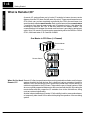
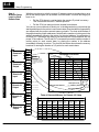
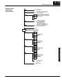
Designing the System
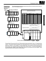
The following remote slave worksheet has been filled in to match the second remote
I/O base of the example system.
Filling Out the
Remote Slave
Worksheet for
Slave #2
MasterModule
Remote I/O
Designing the System
CPU
and
PS
Main Base with Master
Remote Slave Worksheet
Can go in any slot
16
16
16
16
16
I
I
I
O
O
X0-X17
V40400
X20-X37
V40401
X40-X57 Y0-Y17 Y20-Y37
V40402 V40500 V40501
1st Remote
8
I
8
I
X60-X67
X70-X77
V40403
8
O
8
O
Y40-Y47
Y50-Y57
V40502
Slave
Module
2
Remote Base Address ___________ (Choose 1--7)
INPUT
OUTPUT
Slot
Number
Module
Name
Input Address
No. Inputs
0
16ND2
X100
16
1
16ND2
X120
16
2
16TD1
Y60
16
3
16TD1
Y100
16
Output Address
No. Outputs
4
5
6
7
2nd Remote
16
16
16
16
I
I
O
O
X100-X117 X120-X137 Y60-Y77
V40404
V40405
V40503
Slave
Module
Y100-Y117
V40504
X100
40404
Input Bit Start Address: _______V-Memory
Address: V __________
32
Total Input Points Committed________
Y60
40503
Output Bit Start Address: _______V-Memory
Address: V__________
32
Total Output Points Committed________
3rd Remote
8
I
8
I
8
O
8
O
Installation and
Safety Guidelines
X140-X147 X150-X157 Y120-Y127 Y130-Y137
V40406
V40505
Slave
Module
X100 - X117 X120 - X137
Starting Addresses From Appendix B = V40404
Input
Y60 - Y77
Y100 - Y117
V40503
Output
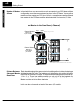
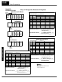
Remote Slave #1 has points X060 to X077 allocated to its inputs and points Y040 to Y057 allocated to its
outputs. This means the starting address for the second remote base inputs is X100 (or higher) and the
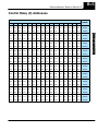
starting address for outputs is Y060 (or higher). Turning to Appendix B, you look up the V-memory
addresses for these points in their respective input and output memory address charts, you find the
starting address for the inputs to be V40404. On the output chart, you find cross-reference 060 with
V40502. These numbers are filled in at the bottom of the worksheet.
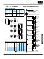
Now let’s do the same thing for third remote I/O base.