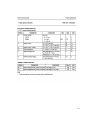
1
PC - BASED GPS TRACKING WITH
IMMOBILIZATION CAPABILITY
THROUGH SMS
By
Aldous C. Eugenio
Kelvin Kristian M. Manalo
Jessiedaniel B. Maribojoc
Albert Joseph A. Pasion
John Paolo V. Ranara
A Design Report Submitted to the School of Electrical Engineering,
Electronics Engineering, and Computer Engineering in fulfilment of
the Requirements for the Degree
Bachelor of Science in Computer Engineering
Mapua Institute of Technology
February 2010
ii
ACKNOWLEDGEMENT
First of all, we would like to thank God for giving us the strength to
pursue this paper (not only for complying with the requirements but doing this
for ourselves to be knowledgeable enough before we graduate). For the wisdom
and knowledge that God has given to us, we offer this paper for His greatness
and we believe that He is the best engineer in the world. We would also like to
acknowledge the support and assistant of our adviser Engr. Jocelyn.
We also thank for the support of our family and friends for giving us
financial and moral support, without them, this paper would be impossible to
finish. We would also like to acknowledge the people who helped us especially in
installing our prototype in the car. Lastly, for our course facilitator Engr. Noel B.
Linsangan, we thank him for teaching us on how to be responsible and for
sharing with us valuable inputs about our paper and for giving us the chance to
learn a part of his expertise.
iii
TABLE OF CONTENTS
TITLE PAGE
i
APPROVAL SHEET
ii
ACKNOWLEDGEMENT
iii
TABLE OF CONTENTS
iv
LIST OF TABLES
vi
LIST OF FIGURES
vii
ABSTRACT
viii
Chapter 1: DESIGN BACKGROUND AND INTRODUCTION
1
Background
Statement of the Problem
Objectives
Significance and Impact of the Design
Scope and Delimitation
Definition of Terms
1
3
3
4
5
7
Chapter 2: REVIEW OF RELATED LITERATURE AND STUDIES
11
Chapter 3: DESIGN PROCEDURES
19
Block Diagram
Data Gathering
Design Procedure
System Flowchart
Circuit Diagram
PCB Layout
Chapter 4: TESTING, PRESENTATION AND INTERPRETATION OF DATA
Testing the Whole System
Testing of GSM Module
Testing Engine Off/On Request
19
21
22
29
33
42
44
44
51
52
iv
Chapter 5: CONCLUSION AND RECOMMENDATION
Conclusion
Recommendation
56
56
57
BIBLIOGRAPHY
58
APPENDICES
59
Appendix
Appendix
Appendix
Appendix
Appendix
Appendix
Appendix
Appendix
A: List of Materials
B: PIC Program
C: Server Source Code
D: Server Software Screenshot s
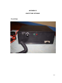
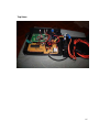
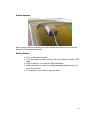
E: Prototype Pictures
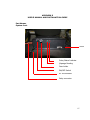
F: System Requirements
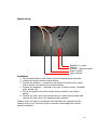
G: User’s Manual and Installation
H: Datasheets
1N4001 General Purpose Rectifiers
1N4148 High-Speed diodes
Maxim Max220-Max 249
Microchip PIC87XA
RT9163 Low Dropout Positive Voltage Regulator
STC9014N NPN Silicon Transistor
Microprocessor Crystal Units
M-89 GPS Module
59
61
71
82
84
86
87
93
94
96
101
105
112
115
117
118
v
LIST OF TABLES
Table
Table
Table
Table
2.1:
4.1:
4.2:
4.3:
AT Commands
System Testing
AT Commands reply Table
Engine Off/On Testing
14
45
51
53
vi
LIST OF FIGURES
Figure
Figure
Figure
Figure
Figure
Figure
Figure
Figure
Figure
Figure
Figure
Figure
Figure
Figure
Figure
Figure
2.1:
2.2:
3.1:
3.2:
3.3:
3.4:
3.5:
3.6:
3.7:
3.8:
3.9:
3.10:
3.11:
3.12:
3.13:
3.14:
GSM Module Circuit
RS-232 Driver Circuit
GPS/GSM Tracker Unit
PC Server
Design Procedure Flow Chart
GPS/GSM tracking unit Flow Chart
GPS/GSM – PC Server Flow Chart
Complete Circuit Diagram
4MHz Crystal Oscillator Circuit
Limiting Resistor for LED (RED)
Limiting Resistor for LED (GREEN)
Transistor Base Resistor
Pull- Up Resistor in PIC16F877A
PIC16F877A PCB Layout
GPS Module PCB Layout
SPDT Relay Board PCB Layout
13
17
19
20
22
29
31
33
36
37
38
39
41
42
43
43
vii
ABSTRACT
GPS tracking in a vehicle with immobilization capability through SMS is a
server based device attached to the vehicle ignition wire. The device can support
tracking and immobilization to the vehicle when a SMS code is received by the
server. For tracking, the server sends a command to the device to request for
the GPS coordinates and sends it back to the server via SMS. The SMS is parsed
to get the X and Y coordinates and compared it to the database. After
comparison, the server sends the exact location of the vehicle to the one
requesting. In case the location is outside NCR, the server will send a message
to the on requesting that the vehicle is out of coverage. For immobilization, the
program uses a SMS code to turn on and off the relay board which is connected
to the ignition wire. The request code changes the value of the EEPROM to save
its last state to avoid reset on the relay board. When the system boots up, the
first thing that the PIC will do is to check for the value of EEPROM. For engine on
request, the relay is turned on and the value of the EEPROM is 1 and for engine
off, request the value of the EEPROM changes to 0. Rebooting the system will
not affect the current state of the relay board not unless a SMS code for engine
off or engine on is sent.
KEYWORDS: (Short Message Service, Global Positioning System, EEPROM,
Server, NCR)
viii
Chapter 1
DESIGN BACKGROUND AND INTRODUCTION
This chapter contains the background of the design project, its basic
components, the history of the topic and its different features.
Background
Nowadays, technology is now offering the widest and powerful tools to
track or to locate a person, vehicle, roads and even the directions when
navigating the sea with the use of Global Positioning System (GPS) but this
doesn’t come with cheaper price. With the use of the free service of the 26 GPS
satellites made by the US Air Force, a device with GPS capability can track
anyone, anywhere with the use of the technology. Gadgets like cell phones,
PDA’s and computers are now capable of acquiring access to the 26 satellites of
the US Air Force but acquiring those gadgets would cost a lot. Tracking the
vehicle is not just the concern of the owner but also its security. The proponents
design a device that can track a vehicle with a device attached to it in which
tracking is done by sending a SMS message to the device and verifies the code
by the microcontroller to validate and perform its requested operation. The
device can also control the vehicles engine to turn off or on.
1
The design is intended to be used as a tracking system to vehicle carrying
the device. It is designed to track the vehicle with the use of a cell phone and a
PC and to secure the vehicle if it is tracked by sending a message to disable the
engine. The car can be turned on again when a requested engine on is received
by the device. The design is mainly composed of a GPS module, GSM module,
PC, relay and microcontroller. GPS module is used as a receiver to access the
GPS satellite and transmit the information gathered. Microcontroller is used to
verify the sent message received by the GSM module and parse it to check the
kind of operation to be done.
The feature of this design is tracking of vehicles from a cell phone to
computer by sending a SMS message to the computer and then to car and when
it is received and verified by the tracker unit, the GSM module will send the
location of the vehicle by its longitudinal and latitudinal position by SMS to the
computer. The computer will compare the coordinates received and display the
exact location of the vehicle through a map. The computer now sends a message
to the sender’s cell phone on the exact location of the car. When engine off is
requested, the relay will automatically open to cut the electricity supply to the
car. Engine on request will automatically close the relay.
2
Statement of the Problem
Vehicle tracking using modern devices available in the market doesn’t
include immobilization on the vehicle. It is only capable to track the exact
location of the vehicle by sending its exact location on the GPS receiver and
through the owner.
In this scenario, the proponents introduced a way to track the vehicle on
its current location using a SMS triggered GPS tracking device that can track and
immobilize the vehicle where ever the owner’s location is by sending a SMS
message to the device attached to the car. Immobilizing the car is by cutting off
engine power with a SMS code decoded by the microcontroller to instruct the
relay connected to the ignition wire to open.
Objectives of this Design
The general objective of the design is to design a tracking and security
system to be implemented on a vehicle with the use of a computer and GSM
module that supports GPS for locating the target through SMS message and
implementing security by cutting the power source of the car using relay.
The following are the specific objectives of the design:
a.) To interface the device using ignition wire.
3
b.) To immobilize the vehicle by automatically disabling the car’s engine
through SMS.
c.) To locate the vehicle travelling within NCR region remotely using a cellular
phone.
d.) To create a database for tracking using mySQL containing locations in
NCR region.
Significance and Impact of the Design
Most of the existing vehicle tracking devices in the market does not
support immobilization. This design is intended to improve the existing vehicle
tracking system to perform vehicle immobility. The applied technology in the
design is based on the current and existing technology and still evolving
depending on its application. Car owners can use the design that travels within
the vicinity of National Capital Region (NCR). Car owners can not only track their
cars but they can also immobilize them. The design can give ideas to other
designers to improve and use the GPS tracking and immobility to its maximum
potential.
The impact of this design will open the local community in developing
more reliable tracking and security system for their vehicles. The design can
lighten up the work of the authorities that are searching for stolen vehicles
equipped with the tracking device. Globally, the design will contribute to
4
maximize the use of GPS and enhance existing design to perform more
accurately.
Scope and Delimitation
The design can only perform those that are listed below and the components
that are presented in the design. Scopes of the design are as follows:
a.) The design uses a GPS module in the device.
b.) A GSM module is used for both the device and to the computer terminal.
c.) A SIM card is used for both of the GSM modules.
d.) Request codes through SMS messages that are recognized by the
microcontrollers are pre defined by the programmers in who it will validate
and decide on what operation to be done.
e.) A SMS starting with <GPSREQ> format is used for vehicle tracking.
f.) A SMS starting with <ONENG> format is used to turn on the relay board.
g.) A SMS starting with <OFFENG> format is used to turn off the relay board.
h.) A Visual Basic.NET program installed in the computer is used to compare
the received coordinates, get its exact locations and send message to the
one requesting via SMS.
i.) Coordinates (longitudinal and latitudinal) are the output signal coming
from the GPS module that will be sent by the GSM module to the
computer.
j.) The input to be fed to the device in the vehicle is a SMS message
following a code depending on the request to be done.
5
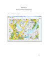
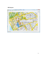
k.) NCR map is attached in the software for viewing the vehicle’s location.
l.) The engine cannot be started when the relay is open (not energized).
The design’s delimitations are the things or conditions that it cannot perform
or function. Delimitations of the design are as follows:
a.) The computer cannot display the exact location of the vehicle outside the
NCR map.
b.) The target vehicle to be tracked when positioned in dead spot of the GPS
satellites is impossible to locate.
(Example of dead spots are tunnels,
basement parking, and underwater)
c.) The displayed map in the computer for tracking will not be in real-time.
d.) GSM module can only accommodate 160 characters, it will only receive
the message if the number goes beyond, but it cannot decode the data
sent.
e.) One out of two SMS sent simultaneously will be processed.
6
Definition of Terms
1.) Differential GPS (DGPS) – is a technique for reducing the error in GPSderived positions by using additional data from a reference GPS.
Source: "Marine Differential GPS". Satellite Navigation. Trinity House.
2.) DTMF – Dual Tone Multi Frequency, signalling is used for telecommunication
signalling over analog telephone lines in the voice-frequency band between
telephone handsets and other communications devices and the switching center.
Source: IEEE Transactions on Consumer Electronics, Vol. 50, No.4 November
2004
3.) GNSS – Global Navigation Satellite Systems, is the standard generic term for
satellite navigation systems that provide autonomous geo-spatial positioning with
global coverage
Source: “A Beginner’s Guide to GNSS in Europe" by IFATCA.
4.) GPS – Global Positioning System (GPS) is part of a satellite-based navigation
system developed by the United States Department of Defense under its
NAVSTAR satellite program.
Source: GPS Overview from the NAVSTAR Joint Program Office. Retrieved
December 15, 2006
7
5.) GPS orbit – fully operational GPS includes 24 or more (28 in March 2006)
active satellites approximately uniformly dispersed around circular orbits with
four or more satellites each.
Source: GPS Overview from the NAVSTAR Joint Program Office. Retrieved
December 15, 2006
6.) GPS signals – each GPS satellite carries a cesium and/or rubidium atomic
clock to provide timing information for the signal transmitted by the satellites.
Source: GPS Overview from the NAVSTAR Joint Program Office. Retrieved
December 15, 2006
7.) ITS – Intelligent Transport System, are those utilizing synergistic
technologies and systems engineering concepts used to develop and improve
transportation systems of all kinds.
Sources: Monahan, Torin. 2007. "War Rooms" of the Street: Surveillance
Practices in Transportation Control Centers
8.) Radio Navigation – relies on radio frequency sources with known locations.
Sources: Global Positioning Systems, Inertial Navigation, and Integration
Mohinder S. Grewal, Lawrence R. Weill, and Argus P. Andrews
8
9.) Microcontroller - is a small computer on a single integrated circuit
consisting of a relatively simple CPU combined with support functions such as a
crystal oscillator, timers, watchdog, serial and analog I/O etc.
Source : Jack Ganssle and Mike Barr ,"Embedded Systems Dictionary".
10.) SMS – Short Message Service, is a communication service standardized in
the GSM mobile communication system, using standardized communications
protocols and allowing the interchange of short text messages between mobile
telephone devices
Source: IEEE Transactions on Consumer Electronics, Vol. 50, No.4 November
2004
11.) Transceiver – is a device that can transmit and receive analog or digital
signals.
Source: A. J. Kloneck, "Simultaneous sending and receiving system"
12.) Ignition key - is the key used in a motor vehicle to turn the switch that
connects the battery to the ignition system and other electrical devices.
Source: Michael Bowler, “The Great Book of Automobiles”.
13.) Relay - is a simple electromechanical switch made up of an electromagnet
and a set of contacts.
Source: I. Sinclair, J. Dunton, ”Practical Electronics Handbook 6th Edition”
9
14.) UART – also known as Universal Asynchronous Receiver Transmitter, is a
piece of computer hardware that translates data between parallel and serial
forms.
UARTs are commonly used in conjunction with other communication
standards such as EIA RS-232. Source: Dario J. Toncich, “Data Communication
and Networking application for Manufacturing Industries”.
15.) Serial Port - is a serial communication physical interface through which
information transfers in or out one bit at a time.
Source: I. Sinclair, J. Dunton, ”Practical Electronics Handbook 6th Edition”
10
Chapter 2
REVIEW OF RELATED LITERATURE AND RELATED STUDIES
The main concept of this design was established with the help of some
existing designs, studies, and principles while conducting this design.
This
organized and synthesized collection of citations of related studies and principles
helps in achieving the design objectives.
Part of this idea came from the three companies in Singapore, namely
Comfort Transportation Pte Ltd., with its subsidiary Yellow-Top Cab, Trans-Island
Bus Services, and CityCab Pte Ltd. that implemented their taxi dispatching using
satellite-based Dispatch System. This technology implemented introduced the
Automatic Vehicle Location and Dispatch Systems or AVLDS. This new satellitebased AVLDS comprises different features, like the interactive voice responses
(IVR), and computerized dispatch system (CDS) which are not included in the
proponents’ design, since the objective is to track and disable the vehicle’s
engine when it is carnapped from the owner. Another is the differential global
positioning system (DGPS) which is a wireless data communications (WDC).
According to the article written by Ziqi Liao, an author of a book published in
IEEE Transactions on Engineering Management, “GPS dispatch systems will play
an increasingly important role in the further improvement of their operations and
services.
The findings of this study should have practical implications to the
11
development of sophisticated public transport system.
Future studies can be
conducted to explore the implementation of on-board vehicle navigation systems
in different environments.”
Another idea came from the design of A. Alheraish, named, Design and
Implementation of Home automation System.
The design used GSM cellular
communication network and integrated it to a microcontroller and a GSM module
for wide range of applications. The microcontroller acted like a brain in of the
system. It is used to communicate with the modules when there is a need to
access in sending or receiving data. GSM module acted as an interface between
the microcontroller and the GSM network
Nowadays, the mode of transmitting data by cellular networks is the GSM
or the Global system for mobile communication. One option in the GSM network
for transmitting data is the SMS or the Short Message Service. The designers
chose the SMS as a mode of transmitting the data. The designer also used a
microcontroller that acted as an interface between the GSM module and the
Personal Computer and GPS module and the automobile. The controller takes the
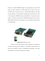
data from the GPS module and translates it to AT commands or the Attention
commands so the module can understand it.
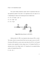
GSM module takes the AT
commands from the microcontroller. Figure below shows a GSM module circuit.
The module is composed of a SIM card holder, which holds the SIM to be used in
12
the module, GSM transmitter/receiver which transmits and receives the SMS
message and a GSM module that is connected to a microcontroller. GSM module
can be easily connected to any ports of a microcontroller and doesn’t need any
interface circuit for it to function normally.
Figure 2.1 GSM Module Circuit
SMS Security System is a design made by some Mapuans where a
controller is used to control a cellular phone attached to a receiver box so that it
can send a message to the cellular phone carried by the owner when the
connected alarm security device is triggered. AT commands are used to control
the built-in modem in a cellular phone. AT is the abbreviation of attention. AT
commands are instructions used to control a modem. Every command line starts
with “AT”, a good reason why modem commands are called AT commands.
13
Some of the AT commands used are: ATD (to dial), ATA (answer),
AT+CMGS (send message), AT+CMSS (send message from storage) and
AT+CMGR (read SMS messages).
There are very large numbers of AT
commands but the designers chose to use a few commands and these are:
AT+CMGR for checking and reading the message and AT+CMGD to delete the
message. With these commands, the designers will know the location of the
vehicle being tracked.
As for this design project, it aims to interface a GSM
module in the car system. The GSM module will send a SMS message that
contains information about the present location of the car. Table 2.2 below
shows a typical AT commands that are supported by some of the known GSM
modem manufacturers.
AT COMMAND
DESCRIPTION
SYNTAX
Most common AT
commands is used to
AT
check if the GSM modem
AT<CR>
is communicating with
the PC.
AT+CMGS
AT command is used to
AT+CMGS = “Receivers
send a message.
number” <CR> Message
<Ctrl-Z>
AT+CMGL
AT command is used to
AT+CMGL=”ALL”<CR>
read messages.
Note: Shows all
messages.
AT command is used to
AT+CMGD=”ALL”<CR>
14
AT+CMGD
delete messages.
Note: Delete all
messages.
AT command is used to
AT+CGMI
know the modems
AT+CGMI<CR>
manufacturer.
AT command is used to
AT+CGMM
know the modems
AT+CGMM<CR>
model.
Table 2.1 AT Commands
Table 2.1 only shows some of the AT commands that are available on
most of the modems available in the market. AT commands of GSM modems
vary depending on the manufacturer but there are still AT commands that are
common to every manufacturer.
Another prototype named SMS Commander Car Alarm System, made by
Kroby, was a good example to base our design project. It used a PIC32
microcontroller installed in the car system. It has a control on/off function via
SMS, where one can query the alarm system’s on/off status anytime. The
position of the car can be known by simply texting the car using a coded
message, and then the coordinates of its present location will be sent to the
owner’s cellular phone. The car movement can be followed on-line using GPRS
and a compatible software. The group’s design can be based on how the SMS
Commander enables text messages to be read and analyzed by the car. Other
15
commands such as stop or lock can be easily done by the car if they will be able
to make the car understand SMS messages.
The system in the article entitled, Real Time Tracking Management
System using GPS, GPRS and Google earth is composed of a GPS module, GooTracking firmware, Goo-Tracking server. The GPS module that the designers
used in their system is based on 8-bit AVR RISC microcontroller which is low
power MCU with 32k ROM and 2k RAM and has several peripherals such as
UART, SPI, I2C to connect GPS/GPRS module, MMC module and GPIO control
module.
The GPS module has two functions, the GPS locates the device position
and the GPRS transmits the device location to the server. The I2C interface is
connected to GPIO Control module which an I/O interface to control external
device such as car alarm or Electronic Control Unit (ECU) for vehicle
immobilization.
The Goo-Tracking firmware is the firmware that performs three phases,
the initialization, the GPS position reading, and the GPS data formatted and
transmitted to Goo-Tracking server via GPRS networks. The initialization phase
prepares the module for reading and transmitting location information. It is
composed of three functions. The first function is to initialize parameters on AVR
microprocessor for UART, SPI, GPIO and timer for GPS reading. The second
16
function is to initialize GPRS/GPS module to set up parameters to warm up GPS
engine, to make a connection to a GPRS network and to connect to the server
via TCP/IP socket. The third function is to initialize MMC module into SPI mode
for data read/write. In the GPS position reading phase, the MCU sends a series
of AT commands to GPRS/GPS module via the UART port. To acquire the current
location of the device, they issue the AT+WGPSPOS command to get the data in
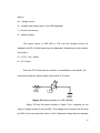
NMEA standard format. This is an example of a circuit interface of microcontroller
to the GPS module.
Figure 2.2 RS-232 Driver Circuit
In Figure 2.2, the circuit includes a serial port female to be connected to
any serial port device and to interface it to the UART of microcontroller, you
need to put a MAX232 IC which is a Multichannel Driver/Buffer. In this way,
interfacing PIC or any MCU to the serial port is possible.
17
In the GPS data formatted and transmitted phase, the NMEA-formatted
data is then parsed and convert to designed format. The format includes the
device ID, session ID, time in UTC format, flags, latitude, longitude, speed, date,
and reserved (Rsv) fields. Each line ended with the symbol (^) represents one
sample of data from a GPS Tracking module in one session or fleet. Samples are
bundled together, ended with the character \n, and transmitted to the Gooserver.
Once the GPS Tracking Module is connected to GPRS networks, it
transmits position information to Goo-Tracking Server which is a commodity
personal computer running a Linux operating system with an open source
software such as Apache web server, PHP, and MySQL program. The server has
three functions to receive the information, to store information in a database,
and to display the information. The receiving function opens a non-blocking
socket to receive data from multiple GPS Tracking Modules simultaneously. The
storing function; formats the receiving data into our database that is designed to
provide real-time query response for real time tracks and to provide search query
response for the post analysis of vehicle tracks.
18
Chapter 3
DESIGN PROCEDURES
This chapter contains the design procedures in making the system, block
diagram, and schematic design. It shows how the system works and how each
parts of the system is connected to the other parts.
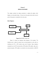
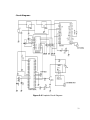
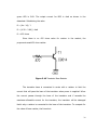
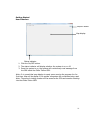
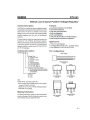
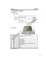
Block Diagram:
GPS MODULE
TX/RX
RELAY
MICROCONTROLLER
GSM MODULE
TX/RX
POWER
SUPPLY
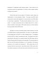
Figure 3.1 GPS/GSM Tracker Unit
Figure 3.1 shows the hardware block diagram of the system. The
hardware part is mainly the parts that are interconnected to each other by
interfacing the PIC to GPS module using Level Converter. Major hardware
components are the PIC microcontroller, GPS module, GSM module, relay and a
personal computer. GPS module is connected to the microcontroller via MAX232
19
while GSM module is directly connected to PIC. These are the parts attached to
the vehicle. Each of this part is designed to perform specific task especially for
the microcontroller to get the GPS coordinates received by the GPS module. The
software includes are the programs stored in the microcontroller and the
software in the computer. The codes in the microcontroller are lines of codes
that perform parsing of the received SMS message and commanding the GSM
module to send GPS coordinates. Codes for PIC are written in Basic using Proton.
AT commands are for codes used in the GSM module while NMEA command
format are used for the GPS control. Power supply is the source of the power for
the hardware components. This can be coming from the car’s battery or from the
cigarette lighter of the car.
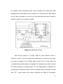
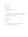
Computer Server:
GSM
MODULE
TX/RX
USB
PORT
COMPUTER
Figure 3.2 PC Server
The computer server which is shown in Figure 3.2 allows the GPS tracker
unit to communicate to each other. The server sends commands to the tracker
unit attached to the vehicle but it can only receive reply from the GPS tracker
unit if the code sent by the server is correct. In the computer server part, the
20
software used is written in Visual Basic.NET that can compare the received
coordinates sent by the device to locate the vehicle’s exact location. The
software provides a graphical view of a map of the National Capital Region
(NCR). After locating the exact location, the computer now sends the request
from the sender of the commands by sending the exact location of the vehicle.
Immobilization of the car is also through the PC server to the GPS tracker unit.
Data Gathering
The proponents gathered data on how to interface the microcontroller to
GPS and GSM modules. Knowing how to interface both of these modules can
eliminate the possibility of having a larger circuitry. Using the data acquired from
IEEE journals, the proponents learned that GPS is interfaced to the
microcontroller by means of a level converter (MAX232). The idea of interfacing
the modules to the microcontroller using a multichannel RS-232 driver/buffer to
adjust the voltage level of UART pins of the microcontroller came from the IEEE
Journal entitled “Real time Tracking Management System using GPS, GPRS and
Google Earth”. Microcontroller UART’s doesn’t recognize 2.8V as a logic high
compared to other TTL pins of the microcontroller. It is because the UART pins
of the microcontroller use Schmitt trigger. The proponents also gathered data in
programming and configuring the GSM modules and the GPS module. The GPS
module can be configured directly to the computer by a software that supports
NMEA data protocol. Acquisition of location can be directly acquired only if there
21
are a minimum of 3 open satellites for the module to use. Less than 3 satellites
open for the module will result with no output. The outputs of the GPS modules
are the longitudinal and latitudinal coordinates of the module which cannot be
directly used to software to show its location. The proponents need to convert
the raw data gathered to exactly locate the target using a map that contains the
location together with a direction.
Design Procedure
Data
Gathering
Data
Gathering
Data Analysis
Simulation
Review of
Related
Literature
Software
Hardware
Circuit design
Programming
Testing
Testing
Software and Hardware
Integration
Design
Testing
Figure 3.3 Design Procedure Flow Chart
22
Figure 3.3 shows the graphical view of the design procedure used by the
proponents. In order to systematically create the proposed topic, the proponents
designed a procedure to follow. The procedure is divided into two parts, the
hardware, and the software.
A. Software
a. Data Gathering
The software part starts from the gathering of required data
including the hardware specifications of the modules to be used for
programming purpose. In this way, the proponents can decide on
what programming language is best to use in developing the
software part.
b. Data Analysis
Data analysis is done to evaluate and verify the hardware
specifications to identify and finalize the programming language to
use. This is also done when testing the finished prototype.
Gathered data are analyzed and verified if the output of the system
is correct.
c. Simulation
Simulation of algorithms or routines in the software is done
especially in the microcontroller programming which uses routines
like decoding SMS message and conversion of the GPS received
23
coordinates to decimal degrees. This will reduce errors in
programming the hardware components.
d. Programming
Programming of the whole system is done after the
simulation of routines or algorithms are verified and tested to be
correct.
Programming
of
the
whole
system
includes
the
programming part in the server and microcontroller. Microcontroller
contains codes written in basic and Visual Basic.NET for the server.
The proponents used EEPROM of the PIC to save the status of the
relay board. The status of the EEPROM will only change if
<ONENG> and <OFFENG> are sent for request.
e. Testing
Testing of the software is done after the hardware part is
finished. Testing of the software in the microcontroller is done by
sending a SMS message request code in the GSM module. Software
testing in the computer server is done by sending a SMS
coordinates to the GSM module to verify its output by using Google
Earth.
24
B. Hardware
a. Data Gathering
This is the process of acquiring information about the
hardware components to be used. Information includes hardware
specifications, interfaces, configuration, and needed power supply.
b. Review of Related Literature
Reviewing related literature will form a foundation for the
proponents in designing the circuit diagram. The proponents can
gather information on the interfaces of the hardware components,
programming
language
applicable,
problems
encountered
in
designing the circuit diagram and the expected output from each of
the components in the diagram. A review on the AT commands is
also done.
c. Circuit Design
After performing the procedures before circuit designing, the
proponents have already gathered vital information regarding the
design of the circuit diagram. The schematic diagram is composed
of GPS module, GSM module, PIC16F877A Microcontroller, voltage
regulator (78L05, RT9163), Level Converter (MAX232) and a relay.
The supply voltage of the circuit is 12V which is fed to the voltage
regulator to regulate the output to 5V for the microcontroller and
the level converter. Another voltage regulator (RT9163) which
25
voltage output is 3.3V is used for the supply of the GPS module.
The module needs 3.3V of supply voltage to operate. A LED is
connected to the GPIO pin of the GPS module to indicate if the
module had acquired a signal to the satellites. A blinking LED
means the module is updating its location while a steady LED
means its not updating. High Speed diode is connected forward
biased to the GPS pin 21 (Real Time Clock and backup SRAM). A
Level Converter (MAX232) is used to convert voltage signal
(TTL/CMOS to RS-232) from the GPS module to be read by the
microcontroller’s UART pin.
Microcontroller uses 4Mhz of crystal oscillator for clock. Clock
is needed for the execution of programs in the microcontroller. A
crystal oscillator is precise compared to RC oscillator/resonator. 2
parallel 33pF capacitor connected to the crystal oscillator to limit its
frequency to 4MHz. The receiver pin of port c is connected to RS232 output of the MAX-232 and the transmitter pin of the GPS
module is connected to the transmitter input of the MAX 232 level
converter. The GSM module is directly connected to RD7 and RD6
pin of Port D of the PIC. Relay board is composed of a 12VDC 30A
Normally open SPST relay, 870 ohm resistor, PNP transistor, LED
and a diode. The resistor connected in series with the base of the
26
transistor that limits the current passing from the microcontroller to
the transistor. A led is connected to the coil of the relay to indicate
if the contacts of the relay are open or close. The diode is used as
a protection diode to the circuit. It blocks current coming from the
coil of the relay when the coil de-energized when power supply is
turned off. This protects other components from sudden burst of
current. Transistor is used as a switch in the relay board. It is
configured as a common-emitter configuration. In this way, it can
have high current output to provide the coil in energizing.
d. Testing
Testing of the circuit can be done part by part or as a whole.
GPS module and GSM module can be tested first in a personal
computer using hyperterminal. Testing the whole system can be
done after all major components are tested to be working correctly
and have been transferred to PCB.
C. Integration of Hardware and Software
After the software and hardware are tested, integration
comes next to test the system as a whole.
27
D. Design Testing
This is the last method to be followed. Required output of
the system must be obtained to validate the system’s performance.
Output of the system is analyzed to verify its reliability and
accuracy. Verification of the systems output can be checked using
Google Earth to verify the x and y coordinates received by GPS
module. Steps after data analysis are done if bugs or errors
occurred during the testing.
28
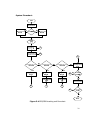
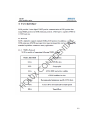
System Flowchart:
Figure 3.4 GPS/GSM tracking unit flow chart
29
Figure 3.4 shows the system flowchart of the GPS tracker unit attached to
the vehicle. The system starts with reading the EEPROM status, a value of 1 to
EEPROM of the microcontroller will close (re-energized) the relay and a value of
0 will open (de-energized). The value of the EEPROM will only change by valid
Off and On engine request (Value of 1 for ONENG, 0 for OFFENG). After reading
the EEPROM, the system initializes the GPS module. If the GPS is initialized, it
will set mCtr for reading the message from the SIM inbox. Reading of SMS
message starts from mCtr = 1 and parse the message for possible request code.
A SMS starting with <GPSREQ> allows the GSM module to send a SMS message
to the server containing the GPS coordinates.
SMS starting with <ONENG>
activates the relay by supplying the coil of the relay. SMS starting with
<OFFENG> de-energized the coil of the relay disconnecting the contacts of the
relay to the coil thus, making the relay in open state. A SMS that doesn’t start
with any pre defined codes by the system will be deleted. After verifying SMS
message, mCtr will increase by one and check it again for possible request code
until it reaches to mCtr = 3. Reaching mCtr = 4 will delete the messages in the
inbox then go back to mCtr = 1. If the GPS module is not initialized or the switch
is turned off, the flow of the system will end.
30
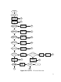
Figure 3.5 GPS/GSM – PC server flow chart
31
Figure 3.5 is the PC server flow chart of the system. The software in the
server starts with initializing the port of the GSM module which is connected to
USB port. After initializing, the software will check if the on button is pressed or
not. Pressing the ON button will start the program to read and delete messages
and setting mCtr to 0. Starting from mCtr = 0(which is the index of the message
in the SIM inbox), checks for possible request code. A SMS starting with
<GPSREQ> commands the server to send a SMS message to the GPS tracker
unit containing “<GPSREQ>” and saves the mobile number of the one
requesting. SMS starting with <ONENG> will also send a SMS message to GPS
tracker unit containing “<ONENG> and will also send a SMS message to GPS
tracker unit then save the mobile number of the sender. Likewise SMS starts with
<OFFENG> but will send a SMS to GPS tracker unit with <OFFENG>.
SMS
containing GPS: is a SMS coming from the GPS tracker unit with GPS
coordinates. The message will be parsed and extract the longitudinal and
latitudinal coordinates. It will then be compared to the database stored in the
server. Depending on the result of comparison, a match result in the database
will show the exact location of the vehicle and then sends the exact location to
the one requesting, non-matching result will display to the server “The GPS
location is out of range or currently not available on the database”. After
verifying the SMS message, the mCtr will increase by 1 until it reaches mCtr = 4.
when mCtr = 4, the system starts to delete the messages stored in the inbox
then reads messages again starting from mCtr = 0.
32
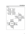
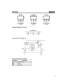
Circuit Diagram:
Figure 3.6 Complete Circuit Diagram
33
Figure 3.6 shows the schematic diagram of the whole system. It is mainly
composed of PIC16F877A, GPS module, GSM module, MAX232 and relay board.
GPS module, PIC16F877A and MAX232 are supplied by 5VDC using a 7805
voltage regulator. The circuit needs 12VDC of supply voltage to function. It is
connected to the input pin of the 7805 voltage regulator to lower it to 5VDC.
Capacitors from the MAX232 connected from C1 +/-, C2 +/-, V+ and V- are
specified by the manufacturer together with their values (0.1uF) because the
capacitors are impossible to be solved due to incomplete circuit presentation
from the datasheet. GPS module uses RT9163 as a voltage source because it
needs 3.6VDC of voltage source.
A high speed diode (1N4148) is connected forward biased from the output
of the RT9163 voltage regulator to the real time clock and SRAM backup pin of
the GPS module. A LED with 33 ohms resistor is connected in GPIO pin of GPS
module to indicate that the module is updating its location. The antenna of the
GPS is connected to the RF_IN and ground of the module. The transmitter pin of
the GPS module is connected to TTL/CMOS input of the MAX232 (T2IN). The
output of the level converter (T2OUT) is then again set as input in RS-232 input
pin (R1IN) and then converted it to TTL/CMOS level (R1OUT). This is done to
convert the voltage level of the GPS module from TTL/CMOS level to RS-232 and
then to RS-232 to TTL/CMOS. The output pin of the MAX232 (R1OUT) can now
be connected to UART pin of the microcontroller which is port RC7. MCLR pin of
34
the PIC16F877A is connected to 5VDC together with a 840 resistor to disable the
pin because it is an active low pin. Vss of the microcontroller is connected to
ground and Vdd is connected to 5V. A 4MHz crystal oscillator is used to
PIC16F877A as clock input for instruction cycle. The 2 33pF capacitors are
connected parallel to the oscillator to trim the oscillating frequency down to
4MHz. GSM module is directly connected to port RD7 and RD6 without any
interface. The relay board is connected to RD4. A LED in series with 430 ohms
resistor connected to RD2 indicates the reading of the GSM module.
The relay board circuit is controlled by the microcontroller because it is
connected to RD4 of the microcontroller. Whenever RD4 is in low state, emitter
of the transistor connected in ground is open and the supply voltage of the relay
is 12V thus, making it in open state. Whenever RD4 is high, emitter is close thus,
voltage supply of the relay changes to 12V-0V allowing the coil of the relay to
energize. A wire connected in output pin of the relay cuts the connection of the
ignition wire. The diode acts a protection to components that may be damaged
when the coil de-energized when supply is cut off. The PNP transistor is used as
(a switch that also has a high current gain due to its common emitter
configuration. LED indicates the status of the relay).
35
Figure 3.7 4 Mhz Crystal Oscillator Circuit
Figure 3.7 shows the 4Mhz crystal oscillator connected to the
microcontroller. The crystal oscillator needs 2 parallel capacitors to trim the clock
resonance to desired clock frequency. Without oscillator capacitors, the clock
frequency can be higher than 4 Mhz. Load capacitance is usually given in the
datasheet of the crystal oscillator. The circuit only needs 4 Mhz of clock
frequency for the operation of the microcontroller that’s why the proponents
need to compute for the oscillator capacitors. The formula for the capacitors is
C1=C2=(2 X Cload) – (Cparasitic – Cinput)
Where:
C1 & C2 – are the parallel capacitors in the oscillator.
Cload – is the capacitance load given by the crystal manufacturer.
Cparasitic – is the Capacitance parasitic, usually 5pF for computation.
36
Cinput – is the Capacitance input.
The crystal oscillator datasheet requires 19pF of capacitance load and a
5pf capacitance parasitic. Since there is no capacitance input, the value for it is
0. Substituting the values to the formula given above indicates that:
C1 = C2 = (2 X 19pF) – (5pf – 0)
C1 = C2 = 38pF – 5pF
C1 = C2 = 33 pF
Figure 3.8 Limiting Resistor for LED (RED)
Limiting resistor for LED is very important when using an LED in a circuit.
This resistor limits the current that will flow from the power source to the LED.
Connecting LED directly to power source may destroy the LED for it will exceed
its peak current especially for high voltage source. For Standard Red LED, the
maximum value of the Voltage Load is 2V. Computing for the required limiting
resistor for Standard Green LED is
R = (Vs – Vl) / I
37
Where:
Vs – Voltage source.
Vl – Voltage load usually given in the LED datasheet.
I – Current from source.
R – limiting resistor
The power source of GPS LED is 3.3V and the forward current for
standard red LED is 40mA based from its datasheet. Substituting to the equation
will result to
R = (3.3V – 2V) / 40mA
R = 32.5 ohms
Since the 32.5 ohms value for resistor is not available in the market, the
proponents used the nearest higher value which is 33 ohms.
Figure 3.9 Limiting Resistor for LED (GREEN)
Figure 3.9 uses the same formula in Figure 3.8 to compute for the
value of limiting resistor from port RD2. The voltage source comes from the port
pin RD2 of the microcontroller which is 4.3V. Maximum Voltage load for standard
38
green LED is 2.6V. The output current for RD2 is 4mA as shown in the
datasheet. Substituting the value
R = (Vs – Vl) / I
R = (4.3V – 2.6V) / 4mA
R = 425 ohms
Since there is no 425 ohms value for resistor in the market, the
proponents used 430 ohm resistor.
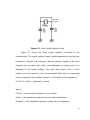
Figure 3.10 Transistor Base Resistor
The transistor base is connected in series with a resistor to limit the
current that will pass the base of the transistor when power is supplied. When
the current passes through the base of the transistor and if exceeds the
maximum allowable current for the transistor, the transistor will be damaged
that’s why a resistor is connected to the base of the transistor. To compute for
the value of base resistor, the formula is
39
Rb = (Vin – Vbe) / Ib
Where:
Rb – Base resistor
Vin – Voltage input
Vbe – forward voltage from base to emitter
Ib – Base current
The output voltage of port RD4 is 4.3V and the maximum forward voltage
for silicon transistor is 0.85V and base current is 4mA that comes from port RD4,
substituting the values in the formula shows that:
Rb = (Vin – Vbe) / Ib
Rb = (4.3V – 0.85) / 4mA
Rb = 862.5 ohms
Since there is no 862.5 ohm resistor in the market, the proponents
considered the highest next value which is 870 ohms.
40
Figure 3.11 Pull - Up Resistor in PIC16F877A
PIC16F877A uses pull-up resistor connected to MCLR to avoid the
microcontroller from resetting. Since MCLR pin of PIC16F877A is inverted,
hanging the pin without connection or simply making the input signal to 0 will
put the microcontroller to unable state. This resistor pulls up the MCLR pin to
almost ground level. Base from the datasheet of the microcontroller, the value of
pull-up resistor must be less than 40k ohms. The voltage source 5V comes from
the output voltage of the 7805 regulator and the output current is 6mA.
Computing for the value of pull-up resistor is given by Ohms Law.
R=V/I
Where:
R – Resistor value
V – Voltage source
I – Current passing to device
R = 5V / 6mA
41
R = 833.33 ohms
Since there is no 833.33 ohm resistor in the market, the proponents used
840 ohm resistor.
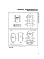
PCB Layout:
Figure 3.12 PIC16F877A PCB Layout
42
GPS Module:
Figure 3.13 GPS Module PCB Layout
Relay Board:
Figure 3.14 SPDT Relay Board PCB Layout
43
Chapter 4
TESTING, PRESENTATION AND INTERPRETATION OF DATA
This chapter shows how the design is tested, presented, and interpreted the
gathered data from the prototype. This chapter also includes the validity and the
reliability of the designed prototype.
Testing the Whole System
Testing the GPS module is the part of the system to be tested first.
Reliability and accuracy of the module depends on the brand of the module.
Holux M-89 warm start at the average of 33 seconds and an average of 36
seconds cold start with less than 1 sec reacquisition time. Accuracy of the
module is a +/- 2 meters. Testing the module is required to verify if the module
can access at least 3 satellites. Failure to access at least 3 satellites will make the
module to standby. An initial testing for the GPS module is done through a PC
connected via serial port. Hyperterminal 7.0 (Windows Vista Version) is used to
see the information gathered by the GPS module. Once powered up and
connected to the serial port, continuous receiving of streams of data is acquired
by the module. Acquisition of the X and Y coordinates of the module starts when
the LED in the GPS module starts to blink. Blinking of the LED indicates that the
module is updating its location. A 2-row Serial LCD is used to show the output of
44
the GPS module. The default or raw data that a GPS module receives are
continuous
streams
of
data
($GPGGA,161229.487,3723.2475,N,12158.3416,W,1,0,9,0,M,,,,0000*18)
which
includes different information (altitude, velocity, position, time, number of
satellites used, etc.) in 1 stream of lines starting with a ‘$’ sign. The only data
that the proponents need is the longitudinal and latitudinal coordinates in a
$GPGGA format which is the number that is before the letter ‘N’ or ‘S’ and after
‘W’ or ‘E’. A routine in the PIC program that parses the streams of data is needed
to extract the needed information regarding the GPS location. After extracting
the required information, it is now converted to decimal degrees value of
longitudinal and latitudinal format. The converted values can now be used as the
GPS position of the module and can be verified using Google Earth or Google
Maps. Below is a table that shows the testing of the GPS module in different
locations.
Vehicle Exact
Location
Coordinates
Received
N and E
Mapua Institute of
Techonlogy, Manila
Point 1 ( Near
14.5907
IEEE)
Mapua Institute of
Techonlogy, Manila
Point 1 ( Near
14.5907
IEEE)
Mapua Institute of
GPS
response
time
Server
response
time
121.9779
62 seconds
3 seconds
121.9779
42 seconds
4 seconds
Server
result
location
Mapua
Institute of
Technoloy,
Muralla Street
(Manila City)
Mapua
Institute of
Technoloy,
Muralla Street
(Manila City)
Mapua
45
Techonlogy, Manila
14.5905
Point 2 (Open
Parking Near
Basketball Court )
Mapua Institute of
Techonlogy, Manila
Point 2 (Open
14.5904
Parking Near
Basketball Court )
Mapua Institute of
Techonlogy, Manila
Point 3 (Along
14.5909
Muralla Street)
121.9783
38 seconds
5 seconds
121.9784
54 seconds
3 seconds
121.9785
80 seconds
3 seconds
14.591
121.9784
56 seconds
4 seconds
Jollibee along
Marcos Highway,
Antipolo City
14.6216
121.1084
45 seconds
3 seconds
Jollibee along
Marcos Highway,
Antipolo City
14.6215
121.1084
85 seconds
3 seconds
Mapua Institute of
Techonlogy, Manila
Point 3 (Along
Muralla Street)
Jollibee along
Marcos Highway,
Antipolo City
14.6215
121.1084
40 seconds
3 seconds
Jollibee along
Marcos Highway,
Antipolo City
14.6216
121.1083
47 seconds
4 seconds
Jollibee along
Marcos Highway,
Antipolo City
14.6215
121.1084
54 seconds
5 seconds
Institute of
Technoloy,
Muralla Street
(Manila City)
Mapua
Institute of
Technoloy,
Muralla Street
(Manila City)
Mapua
Institute of
Technoloy,
Muralla Street
(Manila City)
Muralla Street
Intramuros
near Mapua
Institute of
Technology
(Manila City)
Marcos
Highway near
Sta. Lucia
(Marikina
City)
Marcos
Highway near
Sta. Lucia
(Marikina
City)
Marcos
Highway near
Sta. Lucia
(Marikina
City)
Marcos
Highway near
Sta. Lucia
(Marikina
City)
Marcos
Highway near
Sta. Lucia
46
Ayala Boulevard
corner San
Marcelino, Manila
City
Ayala Boulevard
corner San
Marcelino, Manila
City
Ayala Boulevard
corner San
Marcelino, Manila
City
Ayala Boulevard
corner San
Marcelino, Manila
City
Ayala Boulevard
corner San
Marcelino, Manila
City
Aurora Boulevard
near SM City
Centerpoint,
Quezon City
Aurora Boulevard
near SM City
14.5889
120.9846
30 seconds
5 seconds
14.5889
120.9847
67 seconds
5 seconds
14.5889
120.9847
55 seconds
3 seconds
14.5888
120.9847
48 seconds
3 seconds
14.5889
120.9846
50 seconds
4 seconds
14.6064
121.0195
94 seconds
4 seconds
(Marikina
City)
Ayala
Boulevard
corner San
Marcelino
near SM City
Manila
(Manila City)
Ayala
Boulevard
corner San
Marcelino
near SM City
Manila
(Manila City)
Ayala
Boulevard
corner San
Marcelino
near SM City
Manila
(Manila City)
Ayala
Boulevard
corner San
Marcelino
near SM City
Manila
(Manila City)
Ayala
Boulevard
corner San
Marcelino
near SM City
Manila
(Manila City)
Aurora
Boulevard
near SM Sta
Mesa. (Manila
City)
Aurora
Boulevard
47
Centerpoint,
Quezon City
14.6064
121.0195
56 seconds
3 seconds
14.6064
121.0197
67 seconds
3 seconds
14.6065
121.0198
53 seconds
3 seconds
14.6065
121.0195
55 seconds
4 seconds
Santolan Road
corner EDSA, San
Juan Metro Manila
14.6108
121.0547
89 seconds
5 seconds
Santolan Road
corner EDSA, San
Juan Metro Manila
14.611
121.0557
45 seconds
4 seconds
Santolan Road
corner EDSA, San
Juan Metro Manila
14.6111
121.0556
69 seconds
3 seconds
Santolan Road
corner EDSA, San
Juan Metro Manila
14.6109
121.0556
57 seconds
3 seconds
Santolan Road
corner EDSA, San
Juan Metro Manila
14.6108
121.0556
34 seconds
3 seconds
14.6145
121.0708
35 seconds
3 seconds
Aurora Boulevard
near SM City
Centerpoint,
Quezon City
Aurora Boulevard
near SM City
Centerpoint,
Quezon City
Aurora Boulevard
near SM City
Centerpoint,
Quezon City
E.Rodriguez
Avenue corner
Katipunan Avenue,
Pasig City
E.Rodriguez
near SM Sta
Mesa. (Manila
City)
Aurora
Boulevard
near SM Sta
Mesa. (Manila
City)
Aurora
Boulevard
near SM Sta
Mesa. (Manila
City)
Aurora
Boulevard
near SM Sta
Mesa. (Manila
City)
EDSA near
Camp Krame,
San Juan
Metro Manila
EDSA near
Camp Krame,
San Juan
Metro Manila
EDSA near
Camp Krame,
San Juan
Metro Manila
EDSA near
Camp Krame,
San Juan
Metro Manila
EDSA near
Camp Krame,
San Juan
Metro Manila
E. Rodriguez
Avenue cor
Katipunan
Near Petron
(Pasig City)
E. Rodriguez
48
Avenue corner
Katipunan Avenue,
Pasig City
E.Rodriguez
Avenue corner
Katipunan Avenue,
Pasig City
E.Rodriguez
Avenue corner
Katipunan Avenue,
Pasig City
E.Rodriguez
Avenue corner
Katipunan Avenue,
Pasig City
Marcos Highway
corner Sumulong
Highway, Antipolo
City
Marcos Highway
corner Sumulong
Highway, Antipolo
City
Marcos Highway
corner Sumulong
Highway, Antipolo
City
Marcos Highway
corner Sumulong
Highway, Antipolo
City
Marcos Highway
corner Sumulong
Highway, Antipolo
City
Peace Village,
Antipolo City
Peace Village,
Antipolo City
Avenue cor
Katipunan
Near Petron
(Pasig City)
E. Rodriguez
Avenue cor
Katipunan
Near Petron
(Pasig City)
E. Rodriguez
Avenue cor
Katipunan
Near Petron
(Pasig City)
E. Rodriguez
Avenue cor
Katipunan
Near Petron
(Pasig City)
E. Rodriguez
Avenue cor
Katipunan
Near Petron
(Pasig City)
14.6145
121.0714
45 seconds
3 seconds
14.6146
121.0714
110
seconds
4 seconds
14.6146
121.0716
68 seconds
4 seconds
14.6146
121.0714
51 seconds
3 seconds
14.6253
121.1255
34 seconds
3 seconds
14.6255
121.1256
71 seconds
4 seconds
Out of Map
Coverage
14.6255
121.1255
58 seconds
3 seconds
Out of Map
Coverage
14.6254
121.1257
62 seconds
4 seconds
Out of Map
Coverage
14.6251
121.127
51 seconds
3 seconds
Out of Map
Coverage
14.6151
121.1915
62 seconds
3 seconds
14.6151
121.1915
53 seconds
5 seconds
Out of Map
Coverage
Out of Map
Coverage
49
Peace Village,
Antipolo City
Peace Village,
Antipolo City
Peace Village,
Antipolo City
14.615
121.1915
74 seconds
5 seconds
14.6153
121.1913
66 seconds
4 seconds
14.6153
121.1915
42 seconds
5 seconds
Out of Map
Coverage
Out of Map
Coverage
Out of Map
Coverage
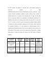
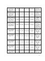
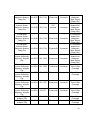
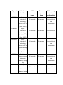
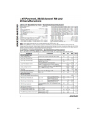
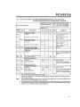
Table 4.1 System Testing
Table 4.1 shows different location acquired by the GPS. The tests are
performed in different locations with the server located at Antipolo, Rizal. Each of
the location is tested five times and gathered its GPS coordinates together with
the server response time to the request and GPS response time. GPS response
time corresponds to the time taken for the GPS device to reply to the server
while the server response time is the time taken for the server to reply to the
requesting party. In different locations, there are different GPS and server
response time. It depends on where the location of the vehicle is (open or closed
area), GPS response time takes longer when the vehicle is in a closed area and
faster when it is in an open area. The average time it takes to reply to the
servers is 57.4seconds. The server response time takes longer when the network
is having traffic but in normal operation, the server response time takes only
about 4.2 seconds. Adding both responses time will give the total time it takes to
receive the tracking request from the time a request is sent. Tests done in
locations listed above are tested in one spot. The table shows that there is a
difference between the coordinates that are tested in same location. This is due
to the GPS accuracy +/- 2m which is equivalent to a 0.0001 decimal in the GPS
coordinates.
50
Testing of GSM module
Another major part of the system is the GSM module. This module can
also be tested in a PC using serial port and a Hyperterminal 7.0 (Vista Version).
First way to test GSM module is to use a hyperterminal and use AT commands if
it is supported. If the said module is supported by a certain command, it will
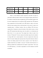
output an “OK” to a certain AT command sent to the module. Table below shows
an example of AT command testing.
AT Command
Reply of the hyper terminal
AT
OK
AT+CMGS=?
OK
AT+CMGF=?
OK
AT+CMGD=?
OK
AT+CMGR=?
OK
Table 4.2 AT commands reply table
The given AT commands in Table 4.2 are the basic commands that are
needed to send, receive, and delete messages. The reply “OK” of the computer
only means that the computer is communicating to the GSM module. The
proponents used AT+CMGS = ”09272872312” <CR> hello <ctrl+ Z>. for testing
51
the module in sending a SMS message. The recipient 09272872312 received the
text message “hello” after commanding the GSM module in the hyperterminal.
The command “AT” with a reply of “OK” means that the PC and the GSM module
are communicating to each other. AT+CMGF is a command that sets the GSM
module reading format. AT+CMGR is an AT command that shows the message in
a specified index. The proponents tested the GSM module by typing in the
hyperterminal AT+CMGR=0 and reply of “OK” is received. This means that, there
is no message saved located in index 0 of the sim card inbox. AT+CMGD is a
command that deletes a message depending on the specified index in the sim
card. AT+CMGD=0 deletes a message in index 0 of the sim card. The testing
shown above is also used in testing GLOBE Tattoo for using it as a GSM module.
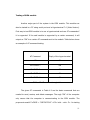
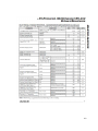
Testing Engine Off/On Request
The system is also tested using the Engine Off/On capability. For safety
purposes, the test is done in a stationary vehicle in which the vehicle is turned
on. The proponents decided to perform this kind of test to prevent accident.
Even if the vehicle is stationary, the immobilization is still applicable. Below is a
table that shows the time it takes for the server to send a confirmation message
to the requesting party when Off/On engine is requested.
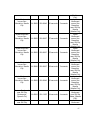
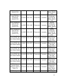
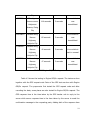
52
Request
Vehicle Exact
GPS
Server
SMS message
Code
Location
response
response
sent as
time
time
confirmation
62 seconds
4 seconds
Your vehicle is
<OFFENG>
Mapua
Institute of
Techonlogy,
now
Manila Point 1
immobilized.
( Near IEEE)
<ONENG>
Mapua
Institute of
79 seconds
5 seconds
Your vehicle is
back to normal.
Techonlogy,
Manila Point 1
( Near IEEE)
<OFFENG>
Mapua
Institute of
54 seconds
3 seconds
Your vehicle is
Techonlogy,
now
Manila Point 2
immobilized.
(Open Parking
Near Basketball
Court )
<OFFENG>
E.Rodriguez
Avenue corner
40 seconds
5 seconds
Your vehicle is
Katipunan
now
Avenue, Pasig
immobilized.
City
<ONENG>
E.Rodriguez
Avenue corner
Katipunan
58 seconds
4 seconds
Your vehicle is
back to normal.
Avenue, Pasig
53
City
<OFFENG>
Your vehicle is
E.Rodriguez
Avenue corner
110 seconds
5 seconds
now
immobilized.
Katipunan
Avenue, Pasig
City
<OFFENG>
Your vehicle is
Jollibee along
Marcos
85 seconds
3 seconds
now
immobilized.
Highway,
Antipolo City
<ONENG>
Jollibee along
Marcos
40 seconds
3 seconds
Your vehicle is
back to normal.
Highway,
Antipolo City
<OFFENG>
Jollibee along
Marcos
Your vehicle is
47 seconds
3 seconds
Highway,
now
immobilized.
Antipolo City
Table 4.3 Engine Off/On Testing
Table 4.3 shows the testing in Engine Off/On request. The tests are done
together with the GPS request code. Parts of the GPS test are done with Engine
Off/On request. The proponents first tested the GPS request code and after
recording the data, some places are also tested for Engine Off/On request. The
GPS response time is the time taken by the GPS tracker unit to reply to the
server while server response time is the time taken by the server to send the
confirmation message to the requesting party. Adding both of the response time
54
is the time taken by the whole system to relay the confirmation message to the
requesting party. The average time for the GPS response time is 64 seconds
while the average for the server response time is 4 seconds. The time taken for
these tests are dependent on the delay of the system in reading the SMS and the
delay caused by the network.
Requesting correct format for turning on the engine is the same as the
conditions in requesting the exact location and in turning off the engine.
Partial correct format is also the same for the correct format. Requesting
incorrect format to the server will not trigger the server to request to the GPS
tracker unit
55
Chapter 5
CONCLUSION AND RECOMMENDATION
This chapter contains the overall conclusion regarding the design. This chapter
also includes the recommendation for the design to improve its function,
reliability, and accuracy.
Conclusion
The design, after several testing, has conformed to the stated objectives
that include the reliability, accuracy of the GPS module and security by means of
immobilization of the vehicle. The general objective is also met by the design.
The design can track vehicle using GPS module by sending a SMS message to
the GSM module. The immobilization of the vehicle is also met by cutting of the
electrical power to the engine by interfacing the design to the ignition wire. The
database made for the design is almost complete for NCR regions. The design is
also tested in different scenarios; still it performs its task. Accuracy of the design
in tracking is almost the same as the output of Google Earth which is taken from
the satellite which is very accurate. Overall the functionality of the design can
greatly contribute to resolving problems on carnapping in the country. Sooner or
later, the design will be introduced to the market as a reliable product for
tracking and security purpose for automotives.
56
Recommendations
The proponents recommend to individuals interested to the design to
greatly improve the tracking functionality as well as the security functions.
Tracking of the vehicle as recommended by the proponents must be broader
than NCR to increase the reliability of the system within Luzon. In this way,
outside the NCR will not be considered to be a dead spot by the computer
server. For better and faster way to track the vehicle, the proponents also
recommend that the tracking must be done in real time. Furthermore, they
encourage that all interested researchers should find a way to minimize the
overlapping of messages when simultaneous testing is done. The proponents
also recommend that the interface between the design and the car must be done
using the ECU of the car. But this method is much complicated, costly, and affect
–
dangerous
–
that
–
might
the
–
cars
-
performance.
57
BIBLIOGRAPHY
"Marine Differential GPS". Satellite Navigation. Trinity House.
IEEE Transactions on Consumer Electronics, Vol. 50, No.4 November 2004
“A Beginner’s Guide to GNSS in Europe" by IFATCA.
GPS Overview from the NAVSTAR Joint Program Office. Retrieved December 15,
2006
Monahan, Torin. 2007. "War Rooms" of the Street: Surveillance Practices in
Transportation Control Centers
Global Positioning Systems, Inertial Navigation, and Integration
Mohinder S. Grewal, Lawrence R. Weill, and Argus P. Andrews
"Embedded Systems Dictionary" by Jack Ganssle and Mike Barr
IEEE Transactions on Consumer Electronics, Vol. 50, No.4 November 2004
A. J. Kloneck, "Simultaneous sending and receiving system"
APPENDIX A
LIST OF MATERIALS
Quantity
Component Name
Price per piece
Total
1
SMS module
PHP 4,500.00
PHP 4,500.00
1
HOLUX GR-89 GPS module
PHP 4,500.00
PHP 4,500.00
1
MAX232 IC
PHP 50.00
PHP 50.00
1
PIC16F877A
PHP 175.00
PHP 175.00
8
0.1 uF Ceramic Capacitor
PHP 2.00
PHP 16.00
3
35V – 22uF Electrolytic
PHP 5.00
PHP 15.00
Capacitor
2
78L05 Voltage Regulator
PHP 15.00
PHP 30.00
3
LED
PHP 2.50
PHP 7.50
1
16V – 47uF Electrolytic
PHP 5.00
PHP 5.00
Capacitor
4
2 pin female connector
PHP 5.00
PHP 20.00
1
8 pin female connector
PHP 22.00
PHP 22.00
2
¼W 1k Resistor
PHP 1.00
PHP 1.00
1
40 pin IC socket
PHP 15.00
PHP 15.00
1
4Mhz Crystal Oscillator
PHP 20.00
PHP 20.00
2
33pF Ceramic Capacitor
PHP 2.00
PHP 4.00
1
16V – 470uF Electrolytic
PHP 5.00
PHP 5.00
Capacitor
59
1
¼W 22k Resistor
PHP 1.00
PHP 1.00
1
½W 2.7K Resistor
PHP 1.50
PHP 1.50
1
Black Casing
PHP 175.00
PHP 175.00
1
Relay Board
PHP 150.00
PHP 150.00
TOTAL:
PHP 9,713.00
60
APPENDIX B
PIC PROGRAM
Device 16F877A
Declare XTAL 4
DECLARE WATCHDOG = OFF
DECLARE FSR_CONTEXT_SAVE = ON
ALL_DIGITAL=TRUE
REMARKS ON
Declare
LCD_DTPIN
PORTC.0
Declare
LCD_RSPIN
PORTD.0
Declare
LCD_ENPIN
PORTD.1
Declare LCD_LINES
2
Declare LCD_INTERFACE
4
HSERIAL_BAUD = 4800
HSERIAL_RCSTA = %10010000
HSERIAL_TXSTA = %00100100
HSERIAL_CLEAR = On
DECLARE SERIAL_DATA 8
Symbol T9600 = 84 NO_LIST
Symbol T4800 = 188
NO_LIST
61
dim ctr as byte, alertCtr as byte,UTC as byte
dim latWhole as word,latDec as word,latN as float
dim latI as byte
dim longWhole as word,longDec as word,longN as float
dim longI as byte
dim pfi as byte
dim RQCtr as byte
dim myMsg[80] as byte
dim mCtr as byte
dim idx as byte
dim mMode as byte
dim eStat as byte
TRISA=$FF
TRISB=$7F
TRISC=$80
TRISD=$A8
PORTB.7=0
PORTD.2=0
eStat=EREAD 0
62
if eStat=1 then
PORTD.4=1
else
PORTD.4=0
endif
cls
Print At 1,1,"INITIALIZING"
Print At 2,1,"DEVICE..."
delayms 8000
PROG_MAIN:
cls
Print at 1,1, "GPS:Initializing"
pfi="0"
while pfi="0"
HSerIn [Wait("$GPGGA,"),UTC, Wait(","), DEC4 latWhole, DEC5 latDec,
latI, Wait(","), DEC5 longWhole, DEC5 longDec ,longI,Wait(","),pfi]
wend
63
cls
Print at 1,1, "GPS: Init OK"
delayms 2000
while 1
gosub smsRead
wend
smsRead:
for mCtr=1 to 3
for ctr=0 to 79
myMsg[ctr]=32
next ctr
cls
Print at 1,1,"READING MSG ",DEC mCtr
msgGR:
PORTD.2=1
SEROUT PORTD.6, T9600,["AT+CMGR=",DEC mCtr,13]
SERIN PORTD.7,
T9600,3000,msgOE,[Wait(34),Wait(34),Wait(34),Wait("<GPSREQ>")]
64
cls
Print at 1,1,"GPS REQ MSG ",DEC mCtr
delayms 2000
mMode=1
gosub WriteData
gosub smsSend
goto delSMS
msgOE:
SEROUT PORTD.6, T9600,["AT+CMGR=",DEC mCtr,13]
SERIN PORTD.7,
T9600,3000,msgNE,[Wait(34),Wait(34),Wait(34),Wait("<ONENG>")]
cls
Print at 1,1,"ON REQ MSG ",DEC mCtr
eStat=1
EWRITE 0,[eStat]
PORTD.4=1
delayms 2000
mMode=2
gosub WriteData
65
gosub smsSend
goto delSMS
msgNE:
SEROUT PORTD.6, T9600,["AT+CMGR=",DEC mCtr,13]
SERIN PORTD.7,
T9600,3000,msgTO,[Wait(34),Wait(34),Wait(34),Wait("<OFFENG>")]
cls
Print at 1,1,"OFF REQ MSG ",DEC mCtr
eStat=0
EWRITE 0,[eStat]
PORTD.4=0
delayms 2000
mMode=3
gosub WriteData
gosub smsSend
goto delSMS
msgTO:
cls
Print at 1,1,"NO REQ MSG at"
Print at 2,1,"MSG ",DEC mCtr
66
delayms 3000
PORTD.2=0
delSMS:
SEROUT PORTD.6, T9600,["AT+CMGD=",DEC mCtr,13]
delayms 3000
next mCtr
return
smsSend:
RQCtr=1
PORTB.7=1
delayms 3000
PORTB.7=0
startSending:
cls
Print at 1,1, "SENDING ALERT #", DEC RQCtr
SEROUT PORTD.6 , T9600, ["AT+CMGS=",34,"09052777430",34,13]
67
delayms 1000
if mMode=1 then
SEROUT PORTD.6 , T9600, ["GPS: ",latI,": ",DEC4 latN,", ",longI, ": ", DEC4
longN]
elseif mMode=2 then
SEROUT PORTD.6 , T9600, ["Engine ON"]
else
SEROUT PORTD.6 , T9600, ["Engine OFF"]
endif
delayms 1000
SEROUT PORTD.6 , T9600, [26]
delayms 10000
'if RQCtr>1 then
' goto smsOut
'else
'
RQCtr=RQCtr+1
'
goto startSending
68
'endif
smsOut:
delayms 1000
return
WriteData:
HSerIn [Wait("$GPGGA,"),UTC, Wait(","), DEC4 latWhole, DEC5
latDec, latI, Wait(","), DEC5 longWhole, DEC5 longDec ,longI,Wait(","),pfi]
cls
Print at 1,1, latI,": ",DEC4 latWhole,".",DEC4 latDec
Print at 2,1, longI, ": ", DEC5 longWhole, ".",DEC4 longDec
latN=latWhole//100
latN=latN + latDec/10000
latN=latN /60
69
latWhole=latWhole/100
latN=latWhole+latN
longN=longwhole//100
longN=longN + longDec/10000
longN=longN /60
longWhole=longWhole/100
longN=longWhole+longN
cls
Print at 1,1, latI,": ",DEC4 latN
Print at 2,1, longI, ": ", DEC4 longN
Return
End
70
APPENDIX C
SERVER SOURCE CODE
Imports System.IO.Ports
Imports MySql.Data.MySqlClient
'===========================NOTES
'
MESSAGE DELETING
Public Class Main
Dim mobile_no(4) As String
Dim message(4) As String
Dim messagelocation As Integer
Dim default_mobile_no As String = "09062884499"
Dim gps_mobile_no As String = "09396592140"
Dim nameloc As String = ""
Dim command As String
Dim MainSwitch As Boolean = False
Dim usbport As String = "COM3"
Private Sub Main_Load(ByVal sender As System.Object, ByVal e As
System.EventArgs) Handles MyBase.Load
MainStatusLabel.Text = "Initializing...."
Timer_Initial.Start()
End Sub
Private Sub btnSwitch_Click(ByVal sender As System.Object, ByVal e As
System.EventArgs) Handles btnSwitch.Click
If MainSwitch Then
btnSwitch.Text = "ON"
ManualModeToolStripMenuItem_Click(sender, e)
MainSwitch = False
Else
btnSwitch.Text = "OFF"
AutomaticModeToolStripMenuItem_Click(sender, e)
MainSwitch = True
End If
End Sub
Private Sub Timer_Initial_Tick(ByVal sender As System.Object, ByVal e As
System.EventArgs) Handles Timer_Initial.Tick
init_mes()
Timer_Initial.Stop()
71
MainStatusLabel.Text = "Initializing.... Done"
End Sub
Private Sub ExitToolStripMenuItem_Click(ByVal sender As System.Object,
ByVal e As System.EventArgs) Handles ExitToolStripMenuItem.Click
Me.Close()
End Sub
Private Sub ManualModeToolStripMenuItem_Click(ByVal sender As
System.Object, ByVal e As System.EventArgs) Handles
ManualModeToolStripMenuItem.Click
MainSwitch = False
ManualModeToolStripMenuItem.Checked = True
AutomaticModeToolStripMenuItem.Checked = False
Label2.Enabled = True
Label3.Enabled = True
txtGPSE.Enabled = True
txtGPSN.Enabled = True
btnUp.Enabled = True
btnDown.Enabled = True
btnLeft.Enabled = True
btnRight.Enabled = True
btnLocate.Enabled = True
Timer_AutomaticMode.Stop()
MainStatusLabel.Text = "System is off"
End Sub
Private Sub AutomaticModeToolStripMenuItem_Click(ByVal sender As
System.Object, ByVal e As System.EventArgs) Handles
AutomaticModeToolStripMenuItem.Click
MainStatusLabel.Text = "Starting automatic mode.."
MainSwitch = True
ManualModeToolStripMenuItem.Checked = False
AutomaticModeToolStripMenuItem.Checked = True
Label2.Enabled = False
Label3.Enabled = False
txtGPSE.Enabled = False
txtGPSN.Enabled = False
btnUp.Enabled = False
72
btnDown.Enabled = False
btnLeft.Enabled = False
btnRight.Enabled = False
btnLocate.Enabled = False
Timer_AutomaticMode.Start()
End Sub
Private Sub AddCoordinatesToolStripMenuItem_Click(ByVal sender As
System.Object, ByVal e As System.EventArgs) Handles
AddCoordinatesToolStripMenuItem.Click
Coordinates_Management.ShowDialog()
Coordinates_Management.Dispose()
End Sub
Private Sub init_mes()
Dim SMSPort As New SerialPort
Dim portdata As String
Dim msgctr As Integer = 0
Dim startCMGR As Integer
With SMSPort
.PortName = usbport
.BaudRate = 115200
.Parity = Parity.None
.DataBits = 8
.StopBits = StopBits.One
.Handshake = Handshake.None
.DtrEnable = False
.RtsEnable = False
.NewLine = vbCrLf
End With
SMSPort.Open()
SMSPort.WriteLine("AT+CMGF=1")
Threading.Thread.Sleep(100)
SMSPort.WriteLine("AT+CMGR=" & msgctr)
Threading.Thread.Sleep(100)
portdata = SMSPort.ReadExisting
startCMGR = portdata.LastIndexOf("+CMGR:")
SMSPort.Close()
msgctr = msgctr + 1
End Sub
Private Sub read_sms()
Dim startCMGR As Integer
Dim messagectr As Integer = 0
73
Dim portdata As String
Dim SMSPort As New SerialPort
With SMSPort
.PortName = usbport
.BaudRate = 115200
.Parity = Parity.None
.DataBits = 8
.StopBits = StopBits.One
.Handshake = Handshake.None
.DtrEnable = True
.RtsEnable = True
.NewLine = vbCrLf
End With
For index As Integer = 0 To 4
SMSPort.Open()
SMSPort.WriteLine("AT+CMGF=1")
'should delay
Threading.Thread.Sleep(100)
SMSPort.WriteLine("AT+CMGR=" & messagectr)
'should delay
Threading.Thread.Sleep(100)
portdata = SMSPort.ReadExisting
startCMGR = portdata.LastIndexOf("+CMGR:")
If startCMGR > 0 Then
'THERE IS A MESSAGE ON THE SELECTED SLOT
portdata = portdata.Remove(0, startCMGR + 19)
mobile_no(messagectr) = portdata.Remove(portdata.IndexOf(""","))
message(messagectr) =
portdata.Substring(portdata.LastIndexOf("""") + 3)
message(messagectr) =
message(messagectr).Remove(message(messagectr).LastIndexOf("OK"))
Else
'THERE are no message
End If
SMSPort.Close()
messagectr = messagectr + 1
If messagectr = 5 Then
messagectr = 0
End If
74
Next
End Sub
Private Sub delete_sms()
Dim messagectr As Integer = 0
Dim SMSPort As New SerialPort
With SMSPort
.PortName = usbport
.BaudRate = 115200
.Parity = Parity.None
.DataBits = 8
.StopBits = StopBits.One
.Handshake = Handshake.None
.DtrEnable = True
.RtsEnable = True
.NewLine = vbCrLf
End With
For index As Integer = 0 To 4
SMSPort.Open()
SMSPort.WriteLine("AT+CMGF=1")
Threading.Thread.Sleep(100)
SMSPort.WriteLine("AT+CMGD=" & messagectr)
Threading.Thread.Sleep(100)
SMSPort.Close()
messagectr = messagectr + 1
If messagectr = 5 Then
messagectr = 0
End If
Next
End Sub
Private Sub Timer_AutomaticMode_Tick(ByVal sender As System.Object, ByVal
e As System.EventArgs) Handles Timer_AutomaticMode.Tick
Timer_AutomaticMode.Stop()
clear_messages()
MainStatusLabel.Text = "Reading SMS...."
Timer_ReadMes.Start()
75
End Sub
Private Sub Timer_ReadMes_Tick(ByVal sender As System.Object, ByVal e As
System.EventArgs) Handles Timer_ReadMes.Tick
Timer_ReadMes.Stop()
init_mes()
MainStatusLabel.Text = "Reading SMS.... Done"
read_sms()
delete_sms()
MainStatusLabel.Text = "Checking SMS...."
'CHECK FOR TRIGERRING MESSAGE
For index As Integer = 0 To 4
If message(index) = String.Empty Then
ElseIf message(index).StartsWith("<GPS>") Then
'This is a gps request
'Send a appropriate sms signal to the device
default_mobile_no = mobile_no(index)
command = "<GPSREQ>"
Timer_SendingCommand.Start()
Exit Sub
ElseIf message(index).StartsWith("<ON>") Then
'This is a engine off request
'Send a appropriate sms signal to the device
default_mobile_no = mobile_no(index)
command = "<ONENG>"
Timer_SendingCommand.Start()
Exit Sub
ElseIf message(index).StartsWith("<OFF>") Then
'This is a engine off request
'Send a appropriate sms signal to the device
default_mobile_no = mobile_no(index)
command = "<OFFENG>"
Timer_SendingCommand.Start()
Exit Sub
ElseIf message(index).StartsWith("GPS:") Then
'Locate this location
'This is a reply message, send to proper requesting number
76
messagelocation = index
Timer_Locate.Start()
Timer_SendingMes.Start()
Exit Sub
End If
Next
MainStatusLabel.Text = "No Command/Request found."
If MainSwitch Then
Timer_AutomaticMode.Start()
End If
End Sub
Private Sub Timer_Locate_Tick(ByVal sender As System.Object, ByVal e As
System.EventArgs) Handles Timer_Locate.Tick
Timer_Locate.Stop()
MainStatusLabel.Text = "GPS Coordinate found..... locating"
Dim gpsN As Double
Dim gpsE As Double
gpsN = Val(message(messagelocation).Substring(8, 7))
gpsE = Val(message(messagelocation).Substring(20, 8))
locate(gpsN, gpsE)
End Sub
Private Sub locate(ByVal gpsN As Double, ByVal gpsE As Double)
Dim myConn As New MySqlConnection
Dim myCommand As New MySqlCommand
Dim myData As MySqlDataReader
Dim xloc As Integer
Dim yloc As Integer
myCommand.Connection = myConn
myConn.ConnectionString = "server=localhost; user id=root;
password=dan; database=gps"
Try
myConn.Open()
Catch ex As MySqlException
MessageBox.Show("Error in opening database")
End Try
myCommand.CommandText = "select * from mapindex where gpsn=" &
gpsN & " and gpse=" & gpsE
77
myData = myCommand.ExecuteReader
If myData.HasRows = False Then
myConn.Close()
MessageBox.Show("The GPS location is out of range or currently not
available on the database.", "GPS Error", MessageBoxButtons.OK,
MessageBoxIcon.Error)
nameloc = "Your vehicle location is out of coverage or not on the
database"
Exit Sub
Else
MainStatusLabel.Text = "Location Found"
myData.Read()
LocationToolTip.ToolTipTitle = "N: " & myData(0).ToString & ", E: " &
myData(1).ToString
xloc = myData(2)
yloc = myData(3)
nameloc = myData(4)
myConn.Close()
draw_point(xloc, yloc, nameloc)
End If
End Sub
Private Sub draw_point(ByVal x As Integer, ByVal y As Integer, ByVal desc As
String)
Dim coor As New Point(x, y)
Dim mappage As Integer = 1
Dim mapx, mapy As Integer
mapx = Math.Truncate(x / 785)
mapy = Math.Truncate(y / 526)
If (mapx = 0 And mapy = 0) Then
PictureBox1.Image =
Global.GPS_Tracking_and_Security.My.Resources._1
ElseIf (mapx = 0 And mapy = 1) Then
PictureBox1.Image =
Global.GPS_Tracking_and_Security.My.Resources._2
ElseIf (mapx = 0 And mapy = 2) Then
PictureBox1.Image =
Global.GPS_Tracking_and_Security.My.Resources._3
ElseIf (mapx = 0 And mapy = 3) Then
78
PictureBox1.Image =
Global.GPS_Tracking_and_Security.My.Resources._4
ElseIf (mapx = 0 And mapy = 4) Then
PictureBox1.Image =
Global.GPS_Tracking_and_Security.My.Resources._5
ElseIf (mapx = 0 And mapy = 5) Then
PictureBox1.Image =
Global.GPS_Tracking_and_Security.My.Resources._6
End If
'convert x and y back to minimal values
x = x - (mapx * 785)
y = y - (mapy * 526)
coor = New Point(x, y)
If x = 0 And y = 0 Then
MessageBox.Show("Your vehicle is at " + desc + ". But it is outside the
map area!", "Information", MessageBoxButtons.OK,
MessageBoxIcon.Information)
Else
LocationToolTip.Show("Your vehicle is at " + desc, PictureBox1, coor)
LocationToolTip.Show("Your vehicle is at " + desc, PictureBox1, coor)
End If
End Sub
Private Sub btnLocate_Click(ByVal sender As System.Object, ByVal e As
System.EventArgs) Handles btnLocate.Click
locate(Val(txtGPSN.Text), Val(txtGPSE.Text))
End Sub
Private Sub Timer_SendingMes_Tick(ByVal sender As System.Object, ByVal e
As System.EventArgs) Handles Timer_SendingMes.Tick
Timer_SendingMes.Stop()
MainStatusLabel.Text = "Sending Location to " + default_mobile_no
Dim SMSPort As New SerialPort
With SMSPort
.PortName = usbport
.BaudRate = 115200
.Parity = Parity.None
.DataBits = 8
.StopBits = StopBits.One
79
.Handshake = Handshake.None
.DtrEnable = False
.RtsEnable = False
.NewLine = vbCrLf
End With
SMSPort.Open()
SMSPort.WriteLine("AT+CMGF=1")
Threading.Thread.Sleep(100)
SMSPort.WriteLine("AT+CMGS=""" & default_mobile_no & """")
SMSPort.WriteLine("Your vehicle is at " & nameloc & "." & Chr(26))
Threading.Thread.Sleep(100)
SMSPort.Close()
MainStatusLabel.Text = "Message sent."
If MainSwitch Then
Timer_AutomaticMode.Start()
End If
End Sub
Private Sub Timer_SendingCommand_Tick(ByVal sender As System.Object,
ByVal e As System.EventArgs) Handles Timer_SendingCommand.Tick
Timer_SendingCommand.Stop()
MainStatusLabel.Text = "Sending commands to device..."
Dim SMSPort As New SerialPort
With SMSPort
.PortName = usbport
.BaudRate = 115200
.Parity = Parity.None
.DataBits = 8
.StopBits = StopBits.One
.Handshake = Handshake.None
.DtrEnable = False
.RtsEnable = False
.NewLine = vbCrLf
End With
SMSPort.Open()
SMSPort.WriteLine("AT+CMGF=1")
Threading.Thread.Sleep(100)
SMSPort.WriteLine("AT+CMGS=""" & gps_mobile_no & """")
SMSPort.WriteLine(command & Chr(26))
Threading.Thread.Sleep(100)
SMSPort.Close()
80
MainStatusLabel.Text = "Command Message Sent."
If MainSwitch Then
Timer_AutomaticMode.Start()
End If
End Sub
Private Sub clear_messages()
For index As Integer = 0 To 4
message(index) = String.Empty
mobile_no(index) = String.Empty
Next
End Sub
End Class
81
APPENDIX D
SERVER SOFTWARE SCREENSHOTS
Server waiting for request:
82
GPS Request:
83
APPENDIX E
PROTOTYPE PICTURES
Front View:
84
Top View:
85
APPENDIX F
SYSTEM REQUIREMENTS
System Requirements:
OS - Windows XP or Windows Vista
Processor – 1.0 GHz or faster (XP) or 2.0 GHz or faster (Vista)
Memory - 1.0 GB RAM (XP) or 2 GB RAM (Vista)
Hard Drive – 20MB free space
Microsoft .Net Framework 3 or higher
Mysql version 6.0 or higher
Usb 2.0 port
Globe Tattoo GSM
86
APPENDIX G
USER’S MANUAL AND INSTALLATION GUIDE
Part Names
System front
Serial
Relay Status Indicator
“”
“”
“”
“”
“”
“”
Message Reading
Indicator
Fuse holder
ON/OFF Switch
DC IN connector
Relay connector
87
System wiring
Negative (+) power
terminal(-) power terminal
Positive
Relay terminal
Relay terminal
Installation
1. Find a secured place in the vehicle where the device can be mounted.
2. Located the device wiring as shown above.
3. Connect the Positive (+) terminal to the vehicle’s positive power supply
that is directly connected to the vehicle’s battery.
4. Connect the Negative (-) terminal to any part of vehicle’s body. (Example:
bolts, screws, etc.)
5. Cut off the ignition wire of the vehicle that is coming to the ignition
switch.
6. Connect the other end of the ignition wire to a single relay terminal and
connect the other end to the remaining relay terminal.
Caution: Ask for a help to an authorize auto-electrician for locating the wire
needed to be cut off. Incorrect wiring connection could damage the vehicle
electrical operation.
88
System Antenna
Note: System antenna must be connected outside the vehicle’s body and must
always be facing towards the sky.
Getting Started
1. Turn on the system switch.
2. The relay status indicator will tell where the system is at ON or OFF
state.
3. Wait for about 1-2 minutes for GPS initialization.
4. When the device is ready the reading message indicator will lit up
every 3-5 seconds.
5. The system is now ready for any operation
89
Software Installation
System Requirements:
OS- Windows XP or Windows Vista
Processor – 1.0 GHz or faster (XP) or 2.0 GHz or faster (Vista)
Memory - 1.0 GB RAM (XP) or 2 GB RAM (Vista)
Hard Drive – 20MB free space
Microsoft .Net Framework 3 or higher
Mysql version 6.0 or higher
Usb 2.0 port
Globe Tattoo GSM
Preparing your computer
1. Insert your Globe Tattoo GSM to any available USB port.
2. Extract the file GPS.zip to C:\ of the computer that will be used as a
server.
3. Run windows command prompt and input “mysql –u root –p
C:\GPS\gpsdata.sql and press enter.
4. Input a password if applicable.
5. Open the location C:\GPS\GPSstart.exe
6. The GPS locator program will now run.
90
Getting Started
User Interface
ON/OFF Button
Map display
Status indicator
1. Click the On/OFF button.
2. The status indicator will display whether the system is on or off.
3. Once the system is on, the system will continuously read message from
the SIM inside the Globe Tattoo GSM.
Note: It is normal that map display is empty upon running the program for the
first time. Map will be display if the system recognizes the coordinate being read.
Note: The server’s texting number will be same as the SIM card number inserting
into the Globe Tattoo GSM.
91
System Functions
GPS Request
Send a message to the server starting with <GPSREQ> to request
for the vehicle location.
A reply message indicating the vehicle’s exact location will be reply
to the requestor.
Engine OFF
Send a message to the server starting with <OFFENG> to request
for a vehicle engine off function.
A reply message indicating the vehicle’s engine off confirmation will
be reply to the requestor.
Engine ON
Send a message to the server staring with <ONENG> to request
for a vehicle engine on function.
A reply message indicating the vehicle’s engine on confirmation will
be reply to the requestor.
Note: Command messages can be only send if the program is on. Otherwise it
will not trigger any action.
92
APPENDIX H
DATASHEETS
93
94
95
96
97
98
99
100
101
102
103
104
105
106
107
108
109
110
111
112
113
114
115
116
117
118
119
120
121
122
123
124