1
DESIGN OF THE GPS TRACKING SYSTEM FOR
MONITORING PARAMETRIC VEHICULAR
MEASUREMENTS WITH ACCIDENT
NOTIFICATION VIA SMS FOR SAUDI GERMAN
HOSPITAL
by
Christopher T. Delarmente
Juris Lan H. Hinanay
Charisma Ann M. Mendoza
Myra A. Tolosa
A Design Report Submitted to the School of Electrical Engineering,
Electronics Engineering, and Computer Engineering in Partial
Fulfillment of the Requirements for the Degree
Bachelor of Science in Computer Engineering
Mapua Institute of Technology
December 2011
Approval Sheet
Mapua Institute of Technology
This is to certify that we have supervised the preparation of and read the design
report prepared by Christopher T. Delarmente, Juris Lan H. Hinanay,
Charisma Ann M. Mendoza, and Myra A. Tolosa entitled Design of the
GPS Tracking System for Monitoring Parametric Vehicular
Measurements with Accident Notification via SMS Saudi German
Hospital and that the said report has been submitted for final examination by
the Oral Examination Committee.
____ _______________
Engr. Dionis A. Padilla
Design Adviser
As members of the Oral Examination Committee, we certify that we have
examined this design report presented before the committee on November,
2011, and hereby recommended that it be accepted in fulfillment of the design
requirements for the degree in Bachelor of Science in Computer
Engineering.
__________________ __
Engr. Janette C. Fausto
Panel Member
_ _________________
Engr. Gorgonio C. Vallestero II
Panel Member
__________________ __
Engr. Joshua B. Cuesta
Chairman
This design report is hereby approved and accepted by the School of Electrical
Engineering, Electronics Engineering, and Computer Engineering in partial
fulfillment of the requirements for the degree in Bachelor of Science in
Computer Engineering.
________________
Dr. Felicito Caluyo
Dean, School of EECE
i
ROLES AND RESPONSIBILITIES OF GROUP MEMBERS
Christopher T. Delarmente
•
Title Page
•
Approval sheet
•
Table of Contents
•
Chapter 4
•
Chapter 5
•
Programmer
Juris Lan H. Hinanay
•
Chapter 1
•
Chapter 2
•
Chapter 3
•
Chapter 5
•
Hardware Assembly
•
Document Organization
Charisma Ann M. Mendoza
•
Acknowledgement
•
Chapter 3
•
Chapter 4
•
Chapter 5
•
Hardware Assembly
•
Data Compilation
Myra A. Tolosa
•
Chapter 4
•
Chapter 5
•
Hardware Assembly
•
Data Compilation
•
References
ii
ACKNOWLEDGEMENT
The completion of the Design Project, GPS TRACKING SYSTEM FOR
MONITORING VEHICULAR ACTIVITIES WITH ACCIDENT NOTIFICATION VIA
SMS would not have been possible without the guidance and the help of
several individuals who in one way or another contributed and extended their
valuable assistance in the preparation and completion of this study.
Engineer Ayra G. Panganiban, who gave support and supervision that help
the development of our design project, and for her patience and persistent
encouragement to complete this study.
Our adviser, Sir Dionis Padilla for giving his time to check on our progress
and sharing valuable insights in the relevance of the study to basic education
not just in the technology sector.
Engineer Joshua B. Cuesta for enlightening our path toward the search for
a proposal, without him we would not have found our design topic, as well as
the advices and recommendation for our design prototype.
E-Gizmo for providing a good offer of the SMS, VDIP and GPS modules
and that we used in the project.
With the support our friends especially our families, we had surpassed the
struggles.
The Almighty God who gave the advocates the knowledge and strength,
patience, perseverance, courage, and for the answered prayers to complete
this design project
iii
TABLE OF CONTENTS
TITLE PAGE
APPROVAL SHEET
i
ROLES AND RESPONSIBILITIES OF GROUP MEMBERS
ii
ACKNOWLEDGEMENT
iii
TABLE OF CONTENTS
iv
LIST OF TABLES
vi
LIST OF FIGURES
vii
ABSTRACT
viii
Chapter 1: DESIGN BACKGROUND AND INTRODUCTION
1
Customer
Statement of the Problem
Solution
Objective
Constraint
Impact
Differentiation
Benefit
Definition of Terms
1
2
3
4
5
5
6
7
8
Chapter 2: REVIEW OF RELATED DESIGN LITERATURES AND STUDIES
12
Global Positioning System
12
Global System for Mobile Communications (GSM) and SMS services
14
Geographic Information System
17
Vehicular Tracking
18
Vehicular Monitoring
20
Wireless Sensor Devices and Communication System
22
Vehicular Routing Problem
23
Automatic Vehicle Location (AVL)
24
DESIGN: Vehicle Accident SMS Alert with GPS Location Notification
25
iv
Chapter 3: DESIGN PROCEDURES
28
Hardware Development
Schematic Diagrams
Software Development
Prototype Development
Definition of Terms
28
31
40
43
45
Chapter 4: TESTING, PRESENTATION, AND INTERPRETATION OF DATA
47
Impact Analysis
GPS Testing
VDIP Module Testing
GSM Module Testing
Accelerometer Testing
47
47
50
53
56
Chapter 5: CONCLUSION AND RECOMMENDATION
58
Conclusion
Recommendation
58
59
REFERENCES
60
APPENDIX
61
Appendix A. Operation’s Manual
System Requirement
Installation Procedures
User’s Manual
Troubleshooting Guides and Procedures
Error Definition
Appendix B. Pictures of Prototype
Appendix C. Datasheet
Appendix D. Others (Program Listing and Letter of Intent)
Appendix E. IEEE Format of the Design
61
61
61
63
63
65
66
70
110
135
v
LIST OF TABLES
Table 3.1 List of Materials
Table 4.1 Testing for the operation of the Global Positioning System (GPS)
Table 4.2 VDIP Module Testing
Table 4.3 GSM Module Testing
Table 4.4 Accelerometer Testing
vi
LIST OF FIGURES
Figure 2.1 Architecture of the mobile device based real-time tracking system
Figure 2.2 Block diagram of the complex automobile system with SMS / GPRS
transmission
Figure 2.3 Block diagram of the Design Vehicle Accident SMS Alert with GPS
Location Notification
Figure 3.1 Block Diagram of Design
Figure 3.2 Schematic Diagram of Microcontroller
Figure 3.3 Schematic Diagram for GSM Module
Figure 3.4 Schematic for GPS Module
Figure 3.5 Schematic for Accelerometer
Figure 3.6 Schematic for VDIP Module
Figure 3.7 Schematic Diagram for the Combined Module for the Design
Figure 3.8 Program Flowchart
Figure 3.9 System Flowchart
vii
ABSTRACT
The Global Positioning System has now become a popular and widely used tool
in terms of the application of tracking a certain target and locating its position.
The main objective of the design is to develop a monitoring device that shall
record parametric developments of the vehicle during its time on the road, and
shall be stored on the memory built on the car. The designed device consists of
the microcontroller, the accelerometer, the VDIP module, the GSM module, and
the GPS module. A windows GUI application shall be included that will serve as
the medium for accessing the data and to view its contents including the location
with the help of Google Maps. The designed device shall have an SMS alert
feature that will be triggered once an accident has occurred. Assessment of the
device showed that the device records data and alerts successfully in an
acceptable timeframe, when the vehicle occurred in an accident such as tilting
and sudden stops, albeit with issues regarding GPS signal strength on bad
weather conditions. From the results, the designers concluded that a device
capable of recording vehicle activities and alerting using SMS is successfully
developed.
Keywords: GPS module, GSM module, VDIP Module, Database, SMS, Vehicle
Monitoring
viii
Chapter 1
INTRODUCTION
Location is a very important piece of information. Knowing one’s location
helps know a person/object’s exact place of setting. When the researchers talk
about location, they are more particular with the place in which the target is, at
the same time they are curious on the speed and direction the target is going in
that specific location and more importantly where is that location.
CUSTOMER
Anyone who has a vehicle of any kind will find that there are plenty of
reasons for wanting a GPS based tracking system installed. The tracking systems
available to consumers are obviously less sophisticated than what a fleet
manager would use but one may still be amazed at what they can do. If
someone is concerned about their car, auto, van or truck being stolen then if it
was tracked they would now know where it was if it went missing. A parent may
want to install one in the car that their kids use so they can monitor not only
where they go, and how long they stay there but also how fast they go. Recent
surveys have suggested that the driving speed of their children is the major
concern of parents when their kids are behind the wheel of a car or even if
someone else is driving. If their kids are in the car they could be at risk. Using a
tracking system could even help a parent to teach their kids to drive responsibly.
If they are employers then they may want to monitor where their company cars
and when their employees are driving them to ensure that they don’t incur extra
1
costs due to unofficial non-company travel or other non-business purposes.
These are the common scenarios that can happen when someone wants to know
what exactly is happening with the vehicles that they use, and most certainly
want to know when, how and why it was used.
STATEMENT OF THE PROBLEM (NEED)
Common knowledge is that most business company with delivery services
often have complaints about on delivery time problems with their clients, or most
oil companies sometimes, more often than not, that they might have someone
delivers oil tanker’s illegal transactions without their knowledge, or mostly on
Bank Company that runs their own Armored Car. In this situation the owner is
unaware whether the driver of the armored car is trustworthy of delivering their
money to their respective patrons, or maybe there are some ordinary public
vehicles that travel in isolated places in which help is out of reach in case an
accident happens and information about accidents is slow or sometimes never
reaches to the public that an accident has occurred, and another problem is the
overwhelming car napping in the current setting, here when a vehicle is stolen it
is sometimes hard to track down the vehicle at once.
Knowing where someone is different from knowing what they are doing in
such place. Thus, most industries and owner of vehicles are very particular on
where their cars are traveling. The illegal use of their vehicle sometime enters
their mind and therefore wonders whether the utilization of their vehicles has
already involved in an illegal transactions other than their own business. Another
2
usefulness of the location is that when accidents occur, the exact place of the
accident can easily be accessed by knowing the shortest route to the accident
site. This is where the application of the GPS comes in. Knowing the location of
the vehicle can help deduce these doings, plus will help observe the vehicle’s
parametric standing.
SOLUTION
GPS or Global Position System is a known device that functions as a way
of knowing one’s exact location and at the same time tracks down the target’s
taken route starting from its origin up to its destination. From here the user can
only become aware of the person’s location and taken route but not the exact
activity of the target. Mostly, the GPS system is often used into vehicles and
monitoring their location, but not the vehicles activity. Researchers, who had
already solved the problem on vehicular tracking, use the GPS in order to keep
record of which route was taken and knowing starting and ending point of the
vehicle. Based on previous reviews on GPS, the functional advantage of this
device uses satellites that triangulate the position of the target. These Satellites
revolve around the planet calculating the disposition of the target’s location,
knowing such information, it therefore generates the coordinates of the location
thus throwing these values into a server and locating the target all at once. GPS
tracking system is used in car tracking devices for tracking data about a car’s
location, direction, speed etc. GPS tracking device comes in handy for transport
3
companies as it enables them to track their vehicles and ensure timely delivery of
goods and services.
Objectives
The objective of the design is to be able to monitor the vehicle’s
parametric data, such as the direction, location and speed. By doing so, the
driver or owner of the vehicle is fully aware of how he is utilizing his car. Another
objective of the design mainly focuses on recording and monitoring the
parametric data, which are stated above, before and after an accident occurs.
The recorded data will be stored as a text file named “log” in the USB drive
mounted on the device. With this information, the users can simply analyze why
the vehicle had ended up in an accident, from here they can conclude whether
the vehicle had sped up or had simply gone out of course. Another objective of
the design is to be able to send early alert notification to the server when an
accident happens. Most accidents that happen in isolated areas eventually
receive help a few hours later; but with the design, the SMS feature is triggered
at once and sends the message in order to get untimely help from those who are
near the accident site. Another objective is that by monitoring frequently the
places of which the vehicle has gone; the user is able to get the analysis of the
place. This simply answers the question why is the vehicle in that place when it
is not supposed to be there.
4
Constraints
GPS system is limited to areas that are known and on-land only; when the
vehicle goes under a tunnel the GPS could no longer detect it. The USB device
mounted into the vehicles records the data of the vehicle’s location, speed, and
direction thus the capacity of the USB is depended on it. When the capacity of
the USB’s storage is low the amount of recorded activity varies with it. The SMS
feature is also dependent on both the Signal and the Provider. When the
accident occurred in an area that has absolutely no signal, the SMS feature won’t
be able to send the message to the server.
Impact
By this innovation, the Company is able to secure their products/produces
in terms of delivery services. When a company knows that their employees are
trustworthy enough to do the job, they are much more secured in letting them
handle their product/produce. And also the company is able to monitor their
employees’ activity even when they are on the road. This innovated tracking
device system also helps us solve the cause of common car accidents by letting
us know exactly what happened before and after the accident occurs. Another
benefit is the updating of information. Sometimes in isolated area where
accidents sometimes happen, help response come in late to save a life, by this
design we use the GPS and SMS technology to be triggered once the accident
happens and send the information immediately to the server to alert that help is
needed.
5
The tracking of vehicles by means of GPS receivers has recreational,
economical and safety benefits in society. GPS equipped rental cars can provide
tourists with driving instructions to tourist sites, and accommodation. This can
reduce stress levels whilst on vacation. Truck drivers are now being made aware
of upcoming low bridges using GPS and digital maps. This combined with
awareness of traffic jams, and suggestions of alternative routes allows for the
cheaper delivery of goods. Police cars, ambulances and fire trucks are also
increasingly being fitted with GPS. This allows emergency operators to direct the
closest units to an emergency, potentially saving lives.
With GPS technology, the routes of the test persons are linked up with the
purpose of the journey. In such a way, a database can be created where the
proportion of trips for shopping can be separated from other journeys. One can
then also see how common it is for journeys to shops to be combined with other
journeys, for instance journeys to and from work, to and from school or to and
from recreational activities.
Differentiation
Most tracking device system mainly concentrates on the location of the
vehicle or target being tracked down. The location itself is a huge piece of
information that lets the person know where the target is and where the target
tends to go, but in the design, the target’s exact location is known and on how
fast the target and the direction of driving is heading to. Another difference here
is that a device shall be installed into the vehicle using the common USB
6
technology in which this USB contains a specific text file format data that
basically records the location, speed, and direction of the vehicle. The device
installed uses a program that shall record the parametric data of the vehicle and
the information about the vehicle’s status that occurs on this specific time. The
data are just text files that list everything down from the exact location to the
vehicle’s direction and speed to know whether the driver has done his job right
or had lying down on the job.
BENEFITS
So as to solve the WH questions of the vehicles’ usage, the researchers
had come up with a design that would not only monitor the vehicle’s location but
would also monitor the speed and direction of the car. Monitoring starts when
the vehicle has started its engine. All the recorded information will be saved into
the USB device mounted on the vehicle, and later be retrieved in order to
analyze the vehicle’s status on the road. By monitoring the vehicle’s data and
location, one can be able to solve common problems that are experienced today,
such as the overwhelming car napping crimes that increase by 0.5 percent per
year. By this design, users can easily track down the stolen vehicle’s site. Car
tracking devices are particularly very useful in tracing stolen cars. If installed in a
car, the police can trace back the stolen car and retrieve it within a short time.
Theft and crime have become everyday news. Car theft is one of the major
crimes that is getting worse year after year. Another problem that can be solved
by the design is the early notification when an accident occurs. Most accidents
7
that happen today tend to give as a very slow update about the occurrence of
the accident, with the design once the accident happens, the SMS feature of the
device mounted into the vehicle is triggered and sends an immediate message to
the server.
DEFINITION OF TERMS
1. GPS – known as Global Positioning System, is a satellite-based navigation
system made up of a network of 24 satellites placed into orbit by the U.S.
2. GSM - (Global System for Mobile communication) is a digital mobile telephony
system that is widely used in Europe and other parts of the world.
3. Accelerometer - is an electromechanical device that will measure acceleration
forces. These forces may be static, like the constant force of gravity pulling at
your feet, or they could be dynamic - caused by moving or vibrating the
accelerometer.
4.
LCD(Liquid
Crystal
Display)
-
a flat
panel
display, electronic
visual
display, video display that uses the light modulating properties of liquid
crystals(LCs). LCs do not emit light directly.
5. Microcontroller - an IC (integrated circuit, or a black chip thing with pins
coming out of it). However it is very common to add additional external
components, such as a voltage regulator, capacitors, LEDs, motor driver, timing
crystals, rs232, etc to the basic IC. Formally, this is called an augmented
microcontroller. But in reality, most people just say 'microcontroller' even if it has
augmentation.
8
6. SMS (Short Message Service) - a method of communication that sends text
between cell phones, or from a PC or handheld to a cell phone. The "short" part
refers to the maximum size of the text messages: 160 characters (letters,
numbers or symbols in the Latin alphabet). For other alphabets, such as Chinese,
the maximum SMS size is 70 characters.
7. Remote Controlled Car - is self-powered model car or truck that can be
controlled from a distance using a specialized transmitter. The term "R/C" has
been used to mean both "remote controlled" and "radio controlled", where
"remote controlled" includes vehicles that are connected to their controller by a
wire, but common use of "R/C" today usually refers to vehicles controlled by a
radio-frequency link
8. Accident - an undesirable or unfortunate happening that occurs unintentionally
and usually results in harm, injury, damage, or loss; casualty; mishap:
automobile accidents.
9. GIS - geographical information science or geospatial information studies is a
system designed to capture, store, manipulate, analyze, manage, and present all
types of geographically referenced data.
10. Server - is a computer program running to serve the requests of other
programs, the "clients". Thus, the "server" performs some computational task on
behalf of "clients". The clients either run on the same computer or connect
through the network.
9
11. USB - is a data storage device that consists of flash memory with an
integrated Universal Serial Bus (USB) interface. USB flash drives are typically
removable and rewritable, and physically much smaller than a floppy disk
12. Text File - is a kind of computer file that is structured as a sequence of lines
of electronic text. A text file exists within a computer file system.
13. Visual Basic (VB) - is the third-generation event-driven programming
language and integrated development environment (IDE) from Microsoft for its
COM programming model. Visual Basic is relatively easy to learn and to use.
14. System Monitoring - systems engineering is a process within a distributed
system for collecting and storing state data.
15. Alert Notification - Alert is a colloquial term used to define a machine-toperson communication that is important and/or time sensitive. An alert contains
user-requested content such as a reminder (important), a notification (urgent),
and ultimately an alert (important and urgent). Alert notification is the delivery of
alerts to recipients.
16. Telecommunication - Telecommunications is a general term for a vast array
of technologies that send information over distances.
17. Sensor - Telecommunications is a general term for a vast array of
technologies that send information over distances.
18. Network Packet - a packet is a formatted unit of data carried by a packet
mode computer network. Computer communications links that do not support
10
packets, such as traditional point-to-point telecommunications links, simply
transmit data as a series of bytes, characters, or bits alone.
19. Light-emitting diode (LED) is a semiconductor light source. LEDs are used as
indicator lamps in many devices and are increasingly used for other lighting.
20. Antenna - is an electrical device which converts electric currents into radio
waves, and vice versa. It is usually used with a radio transmitter or radio
receiver. In transmission, a radio transmitter applies an oscillating radio
frequency electric current to the antenna's terminals, and the antenna radiates
the energy from the current as electromagnetic waves (radio waves).
21. SIM - is an integrated circuit that securely stores the service-subscriber key
(IMSI) used to identify a subscriber on mobile telephony devices (such as mobile
phones and computers)
11
Chapter 2
REVIEW OF RELATED LITERATURE
The significant power of the GPS technology had become a huge aspect in
society’s monitoring systems. Knowing one’s location is a very important factor in
terms of observing a specific target. When this information is obtained, tracking
it down is easy as drawing a line from one point to another. By tracking down
the point from which the target had come from, up to the point of which it shall
stop, is an easy access since the Global Positioning Satellite System makes this
easier for observers to monitor the vehicles course.
Global Positioning System
GPS or Global Positioning System provides two levels of service, Standard
Positioning Service (SPS) and Precise Positioning Service (PPS). The SPS is a
positioning and timing service that is available to all GPS users on a continuous
worldwide basis. SPS is provided on the L1 frequency (1575.42), which contains
the navigation data message and the SPS code signals. The PPS is a highly
accurate military positioning, velocity and timing service which is available to
users authorized by the Department of Defense. Since its inception in 1978, GPS
has fast become the most popular satellite aided navigation system used
worldwide. Many industries, such as civil aviation, shipping and agriculture, have
become quite dependent on this service.
GPS or Global Positioning System as according to the article of Jay
Warrior, Eric McHenry, and Kenneth McGee, “They Know Where You Are” written
12
in January 2003, that the first development of the tracking system was used for
military purposes. The constellation of U.S. military satellites that are used to
guide everything from bombs to ordinary passenger cars, to monitoring assaults
had made a huge development for national security against terrorist attacks. In
Europe, the use of the GPS played a huge role in terms of cellular communication
technologies. The technology depends on a form of triangulation: it requires at
least three cellular base stations to receive a signal from the wireless handset,
and then computes the location from the differences in arrival times of the three
signals.
Through this technology, the military is able to counter these attacks by
using the enemies’ location against them. For communication, the benefits of
location technology aren’t limited to subscribers—it will also help wireless carriers
improve their systems, by making every enabled handset an instrumentation
probe. Signals played an important part since they are called “hints”, as
according to the article, these hints suggest the GPS satellites that will give the
quickest fix on the position. These hints are particularly necessary when the
phone is indoor or the enemy is underground and GPS reception is more limited.
The concept of the GPS mainly applies to monitoring people and knowing
their locations. In the paper Design and Implementation of a Mobile Devicesbased Real-time Location Tracking by Hyo-Haeng Lee, In-Kwon Park, and
Kwang-Seok Hong, this paper proposes a real-time location tracking system
using a GPS module for different mobile devices and multiple users. It focuses on
13
the management and observation of a majority of people can be foretold. The
development was made so the user may acquire and manage location
information of specified subjects, who require individual care in real-time. Such
users include those requiting specific protective measures, children, and the
elderly. In applications to vehicle, this is also the same, the researchers are to
use this basic concept and apply in cars so as to keep track of the vehicle n
terms of security and reliability.
Based on research, navigation enables a user to process his current
location based on GPS data and travel to his desired location, also based on
accurate GPS data. Any user with a working GPS receiver can navigate to a
particular destination, whether traveling on foot, by automobile, by airplane or
by ship. Time is the fourth dimension that GPS is set up to provide, by
synchronizing each GPS receiver to the GPS satellites to provide accurate time to
the user.
Global System for Mobile Communications (GSM) and SMS services
Mobile services are widely used today. In the paperDesign and Implementation
of a Mobile Devices-based Real-time Location Tracking by Hyo-Haeng Lee, InKwon Park, and Kwang-Seok Hong, the use of mobile is to track and to identify
the location of objects in real time. They may use simple, inexpensive nodes
(badges/tags) attached to or embedded in objects and devices (readers) that
receive the wireless signals from these tags to determine their location. One of
the mobile services that can be accessed is the GPS feature. The paper proposes
14
a real-time location tracking system using a GPS module for different mobile
devices. Several users may be required to manage and to observe most of the
subjects (people) being monitored. Another mobile feature adopted is the GIS
that has been implemented on many mobile devices. With the widespread
adoption of GPS, GIS has been used to capture and to integrate data in the field.
GIS APIs are designed to manage GIS data for delivery to a web browser client
from a GIS server. They are accessed with a commonly used scripting language
such as VBA or JavaScript.
In another
paper, Design and Implementation of Real Time Vehicle
Tracking System by Muhammad Adnan Elahi, Yasir Arfat Malkani2, and
Muhammad Fraz, written and proposed in 2007, After collecting positioning data,
it is transmitted using some kind of telemetry or wireless communications
systems. GSM is the most common used service for this purpose.
15
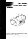
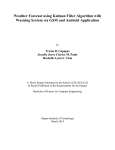
Figure 2.1
Architecture of the mobile device based real-time tracking system
The figure shown above, mainly explains how the GSM works with the
GPS and GIS application. The user receives desired information from the mobile
device, mounted with a GPS receiver, to access the location based service. When
the client transfers longitude and latitude received from the GPS receiver to the
GPS application server via TCP/IP, other mobile client users convey location
information data, accessing the GPS application server.
As reference to the study, the researchers shall require a GPS application
server in mobile devices for wireless communication for the SMS alert system.
Based from the reference, if a mobile device user shall acquire the GPS location
information when the server had sent it, the acquired location information is
transferred to the GPS application server after transforming the coordinates.
16
Then other mobile device users access the multi-user real-time location
information from the GPS application server. The use of the information shall be
used for the purpose of the accident alert system.
Geographic Information System
A Geographic Information System (GIS) is any system to capture, store,
analyze and manage data and associated attributes that are spatially referenced
to Earth and Location Based Services (LBS). GIS are information services
accessible via mobile devices through the mobile network that utilize the location
of the mobile device. GIS analysis software takes GIS data and overlays or
otherwise combines it so that the data can be visually analyzed. It can output a
detailed map, image or movie used to communicate an idea or concept with
respect to a region of interest. This is usually employed by persons who are
trained in cartography, geography or a GIS professional, as this class of
application is complex and takes time to master. The software transforms raster
and vector data sometimes of differing data type, grid or reference systems, into
one coherent image. It can also analyze changes over time within a region.
The application of GIS in the research is to determine the tracking route of a
targeted vehicle. The research shall use the concept of the GIS as reference for
the software development only. Other software for the vehicle monitoring and
tracking shall be developed further during the research.
17
Vehicular Tracking
According to a review, using GPS Tracking for Vehicle and Personnel
Management in Industries on The Rise by Vaishnavikna Pathak, those industries
which are involved in transportation, logistics, manufacturing, etc. have a
number of vehicles that are on the move or transport goods to the different
points of sale. Even, they would require the raw materials to be brought in from
the distant areas, and they have to be brought in perfect time. It is also required
that the vehicles in the fleet are to be monitored regularly about their reach and
return on time, so that the next travel plan and consignment can be delivered.
Personnel tracking help in reducing the labor and unnecessary haggling with
clients by remaining in the uncertain cloud. The GPS tracking device that is fitted
in these vehicles can easily convey the location and the approximate arrival time.
In another research paper, Design and Implementation of Real Time
Vehicle Tracking System by Muhammad Adnan Elahi, Yasir Arfat Malkani2, and
Muhammad Fraz, written and proposed in 2007, tracking was to serve the main
purpose of navigation for location-based applications. Real time vehicle tracking
system is successfully implemented using SMS of GSM network, and GPRS as
transport channel to achieve the desired properties of Automatic Vehicle Location
(AVL) system. The paper covers the hardware and software design of devices
developed to determine and transmit the vehicle’s information, such as its
location, to the remote Tracking Server. Tracking Systems aid in determining the
18
geographic positioning information of vehicles, once collected it will then transmit
it to a remotely located server.
In the same paper, the vehicle’s location is determined using GPS, while
the transmission mechanism can be satellite, terrestrial radio or cellular
connection from the vehicle to a radio receiver, satellite or nearby cell tower.
There may also exist some other alternatives for determining the location in the
environments where GPS signal strength is poor, such as dead reckoning, i.e.
inertial navigation, active RFID systems or cooperative RTLS systems.
In the IEEE paper, GPS Based Marine Vessel Tracking Device by Glenford
A. McFarlane and Joseph Skobla, satellite navigation has started to expand into
other areas such as recreation, security, and emergency response. Without any
reservation, this form of position acquisition is here to stay and can only get
better. In the paper, the goal of the project is to provide GPS tracking solution
for fishing boats. The processing unit is equipped with two communication ports
one dedicated for the GPS receiver and the second for radio link.
Such monitoring of the vehicle’s time is depended on the vehicle’s activity,
whether the target had slowed down or sped up, or has entered a traffic area or
just simply halted momentarily in an isolated area. This is where the study
comes in; monitoring the vehicles’ events helps utilize this information in order to
maximize the industries demands and requirement in terms of delivering trade
and monitoring.
19
Vehicular Monitoring
In the proposed paper, A New Approach of Automobile Localization
System Using GPS and GSM/GPRS Transmission, by Ioan Lita, Ion Bogdan Cioc,
and Daniel Alexandru Visan started in 2006; the paper basically covers the whole
concept of our research on monitoring vehicular activity. The same concept of
tracking and monitoring the vehicle was merely developed for the reasons useful
for adolescent drivers watching by their parents, in case of employees
supervising, etc. The proposed application represents a low cost automotive
localization system using GPS and GSM-SMS services for car localization.
Optional, other parameters can be transmitted to inform the owner about car
parameters like engine state, speed, speed limit exceeding or delimited area
leaving, or giving car commands like engine stopping in theft situation, etc. This
system can be connected to a PC or laptop for settings or for use as navigation
system. Using the GPRS transmission, the presented system can realize car
tracking function, together with automobile parameters and engine monitoring
and alarm event signaling.
20
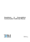
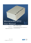
Figure 2.2 Block diagram of the complex automobile system with SMS /
GPRS transmission
In this paper, the monitoring of the vehicle is an optional action in which
every parameter of the vehicle is sent to the mobile of the owner of the car. This
feature of the proposal is impractical since the storage of the cell phone isn’t
large enough to accommodate the data, and impractical since it will annoyingly
keep alerting the owner of his car’s activity, like when the engine starts, speed
limit and area informative. This sort of application is only useful for car theft in
which the request to monitor the car is only made possible when the owner is
away from the vehicle and that the owner had activated the request for
monitoring through the SMS feature. This serves as the alerting system, but the
localization of where the car might have gone will be difficult to find, even with
the use of the tracking system. As a recommendation from the paper, further
development of complex car monitoring and control system is still being studied.
No actual development of the hardware was made, but the concept of the
21
proposed system is shown in Figure1.1. The proposed solution can be used in
other types of application, where the information needed is requested rarely and
at irregular period of time.
Wireless Sensor Devices and Communication System
In the IEEE article, On the Architecture of Vehicle Tracking System Using
Wireless Sensor Devices by Aravind .K. G, Tapas Chakravarty, M. Girish Chandra,
and P. Balamuralidhar, the whole concept of tracking the vehicle down mainly
focuses on the networking GPS of the vehicle itself through the use of low cost,
effective implementation as in contrast to the existing high cost tracking
systems. The whole idea of tracking the vehicle is based on Gateway nodes.
These wireless nodes are addressed by the registration number of the vehicles
which are unique. The GW nodes which are commonly known as road-side units
(RSUs) are installed on the buildings, lamp posts etc. These nodes are connected
to the underlying wired infrastructure (internet) to receive query from the central
server and reply back with the necessary information. As the location of a vehicle
to be tracked is unknown, broadcasting is chosen as mean of communication.
This system too has many other applications like reporting accidents on the
roads, so that nearest ambulance services may reach the spot thereby saving
more lives.
Another article, Development of Tracking Train Detection Device
(COMBAT)by Using Wireless Communication by Noriyuki Nishibori, and Tatsuya
Sasaki, COMBAT stands for Computer and Microwave Balise Aided Train
22
detection. According to the article, The COMBAT comprises a microwave Balise
(interrogator, wayside responder and on-board responder) and a processing unit.
The interrogator and wayside responder are installed close to the entering signal
and starting signal, holding the trackline in between. This system detects the
existence and direction of the train at the detecting point (microwave Balise
installation site).
The main problem of such application is that the information of tracking is
being bounced from one GW node to another, this way of tracking a vehicle is
very impractical due to many interferences that might occur on the location of
the GW nodes. Another problem seen is that the location of the GW nodes itself
which are mounted into posts and buildings, the location of these nodes is not
that reliable because in due time these posts and building might no longer be
able to support the nodes, and might as well distort the signal which can
eventually occur into data loss. In the COMBAT application, though the tracking
of the train is somewhat convenient, the problem seen here is that the train
follows a provided route for them, thus the tracking of the train is irrelevant, and
tracking system is no longer applicable here.
Vehicular Routing Problem
The Vehicle Routing Problem (VRP) can be described as the problem of
designing optimal delivery or collection routes from one or several depots to a
number of geographically scattered cities or customers, subject to side
constraints. Vehicle Routing Problem or VRP is the fundamental problem in the
23
research fields of transportation; various types of VRP are studied to determine
the optimal route under various constraints of locations, distance, time window
and activities. In order to improve the route waste collection a certain type of
algorithm is proposed. But it is difficult to straightly apply one case result to
other cases, because the different constraints cause other difficult problems.
Such problem occurrences in indeterminate since traffic in a location is
unexpected, accidents happens sudden making is one factor for finding routes
that makes a short route become a long way of travel. These factors are out of
hand for the user of the vehicle so it shall be included in the limitation of the
research. Versions of the problem and a wide variety of exact and approximate
algorithms have been proposed for its solution. Exact algorithms can only solve
relatively small problems, but a number of approximate algorithms have proved
very satisfactory. However, several promising avenues of research deserve more
attention, such as search methods.
Automatic Vehicle Location (AVL)
This Automatic Vehicle Location System (AVL) is a complete out-of-thebox low cost vehicle tracking solution: hardware, software and maps, ready to
track. AVL is a combination of GPS and GIS with communications links added to
track, locates, and log fleet vehicles. Customer service is improved by increased
on-time deliveries, and faster response to customer pickup requests using
AVL locate and send nearest vehicles functions. Track your fleet from your
desktop with a low cost fully featured GIS-based map display and AVL system
24
that allows you to track your vehicle real-time on detailed street maps. Benefits
of the AVL system that have been applied:
• Kansas City achieved reduced incident-response time, from 7-15
to 2-3 minutes, with use of AVL.
• Provides graphic or tabular report of vehicle activity (i.e., dwell
time, speed).
• Sweetwater County, WY, almost doubled ridership without
increasing dispatching staff by implementing AVL and CADS.
Operating expenses decreased 50% per passenger mile.
• AVL and CADS allowed St. John's County Council on Aging in
Augustine, FL, to reduce its scheduling, dispatching, and billing
staff by half. Trips per vehicle hour have increased from 0.5 to 2.5.
• Collects driver log for use by payroll.
• Provides graphic or tabular report of vehicle activity (i.e., dwell
time, speed).
DESIGN: Vehicle Accident SMS Alert with GPS Location Notification
In the design paper, Vehicle Accident SMS Alert with GPS Location
Notification by Joshua Borja Cuesta, Maricar Ternida, Eugene Ancheta, Jessica
Bernardino and Dexter Nidoy, the development of their design also mainly
focuses on vehicular Accidents containing a SMS Module for the sending of
25
accident notification and a GPS Module that determines the location of the
accident.
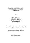
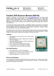
Figure 2.3 Block diagram of the Design Vehicle Accident SMS Alert with
GPS Location Notification
Based from the given block diagram in Figure 2.3, the accelerometer
serves as a sensor that shall be mounted on to the vehicle, this sensor shall
detect inclination and movement of the vehicle. As programmed in the
Microcontroller any strong impact or sudden brakes will trigger the an instruction
to the microcontroller and immediately activating the SMS Module to send out
the alert notification. The GPS module shall be responsible for the accident’s
location which will be also sent out. The SMS Module contains the SIM card fthat
shall sent out the message, also taking note that it should have enough Load or
balance to sent out the message.
26
Based from the design, the Accident alert notification system mainly bases
its action on the accelerometer’s angle of inclination and sensitivity. Using this
related literature, the researchers used most of the concept of the design for the
monitoring of Vehicular Parametric Measurements and location status. Using this
design the researchers innovated and improved most of the feature as based
from the recommendation given.
The difference of the two designs is that a Server and storage was added.
A Server to monitor the vehicle from time to time and shall also act as a data
storage for the LOCATION or ACCIDENT coordinates. While the VDIP Module
was added for the USB Storage interfacing, the reason for the storage, as base
from the recommendations found, is that their design needed storage for the
sending of data. A SIM card is not enough to store the Vehicle’s data location so
a separate storage device was made. It is impractical since the storage of the
cell phone isn’t large enough to accommodate the data.
27
Chapter 3
DESIGN PROCEDURES
The group had used the related literature as cited in Chapter 2 about the
whole idea of the design, with some major modification and altered
improvements. This chapter gives a detailed discussion on how the step-by-step
procedures will be used on the design in order to give the readers the idea on
how the prototype has been created. This also helps the readers to easily
understand on how the group contributed to be able to theorize the development
of the design
Hardware Development
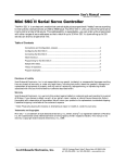
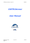
Figure 3.1
Block Diagram of Design
28
Figure 3.1 shows the block diagram which consists of the major parts of
the device. This will help the readers to easily understand how the group came
up with the design. It also shows the primary components of the device.
In developing the research, one must have full imagery on how the
system is going to work. So the first step in doing the study is the development
of the Block Diagram. In Figure 3.0, it can be seen that the whole system is
dependent on the Microcontroller. The microcontroller shall serve as the main
module of the design; it will control most of the device’s functionality.
The GSM Module basically covers the whole concept of SMS alert. This
module is only triggered when the accident occurs. This module is the ready
solution for remote wireless applications, machine to machine or user to machine
and remote data communications in all vertical market applications. GSM uses a
process called circuit switching. This method of communication allows a path to
be established between two devices. Once the two devices are connected, a
constant stream of digital data is relayed. This allows the receiving end to hear
the data being sent before the whole message or data were finished. The
advantage to this is there's no wait time. In addition to the ignition control line,
while the second strip contains all the communication signals and lines to and
from the GSM module, as well as the analogical section of the phones
Next, the GPS module; this module composes of an antenna, that serves
as the device’s main feature for tracking. In this module, such unit must be used
outdoors with a clear view of the sky, and are capable of locking into the signals
29
from the GPS satellites. The signals allow them to calculate the distances to
these satellites, and with that data they can calculate position on the earth’s
surface in latitude and longitude within +/- 100 meters 95 % of the time. This
module is also called the user segment because; this part consists of user
receivers which are hand-held or, can be placed in a vehicle. All GPS receivers
have an almanac programmed into their computer, which tells where each
satellite is at any given moment. The GPS receivers detect, decode and process
the signals received from the satellites. The receiver is usually used in
conjunction with computer software to output the information to the user in the
form of a map. As the user does not have to communicate with the satellite
there can be unlimited users at one time.
The VDIP Module is used to provide a USB interface. Hence gives the ease
of program development for interfacing while providing the convenience of USB
support. This interface shall serve as a pathway of connection from the USB
storage device to the tracking device itself. The USB device, often referred to as
a jump drive, works like a plug-n-play device. Files can be transferred quickly
form one work station to another, as well as to other portable devices like
laptops.
30
The next module to deal with is the Accelerometer, in this module it shall
take responsibility of detecting the vehicle’s movement and inclination. An
accelerometer is an electromechanical device that will measure acceleration
forces. These forces may be static, like the constant force of gravity pulling at
your feet, or they could be dynamic - caused by moving or vibrating the
accelerometer. It is a certain type of sensor, which is sensitive to movement, for
this study it is the vehicle’s. By sensing the amount of dynamic acceleration, one
can analyze the way the device is moving.
And lastly, the main processing unit of the whole tracking device is the
Microcontroller, the functions of the this controls all the modules connected to it,
the GSM, GSP, VDIP modules. The Microcontroller shall contain the instructions
that shall be passed into each module upon operation of the device. This shall be
programmed as to acquire the specific requirements of the design.
Schematic Diagrams
After studying the block diagram’s main picture, next step is design the
Tracking and Vehicular Monitoring device from the block diagram. In order for
the device to become functional, or more importantly be built, one must first be
familiar with the physical and complex structure of the vehicle into which the
device shall be mounted. Once that had been studied thoroughly, next to build is
the individual module of the device. The GPS, GSM, VDIP and Accelerometer
Module are to be designed individually so as not to complicate the circuit. The
Microcontroller shall be programmed as to incorporate these modules.
31
Schematic Diagram of Microcontroller
Figure 3.2
32
Figure 3.2 shows the Microcontroller’s Module. In this module, the
Microncontroller shall serve as the Brain of the device. The Microcontroller
comprises of different instruction inputted anc coded into it. Most of the
instrcutions involved are each of the other modules’ operation. In the Figure
3.2, as shown in order to check whether all other modules are responding, a
LCD was connected so as to monitor the device’s initalization process. Based
from the data sheet provided, the connection from the microcntroller to the LCD
to the Pin labels RC1, RC2, RC3, RD1 and RD0 to the LCD’s Pin labels D4, D5,
D6, D7, E and RS respectiveley. This connection shall output the Initialization of
each modules. Since the program has already been encoded, and the
corresponding Message shall be outputted on LCD Screen. The LCD basically is
used for checking the initialization of each module. It shall output if the
initialization was successful or has failed. Another output message shall be
shown when the car has been in an accident, since the device had been program
to freeze when the accident occurs, the LCD shall display a Locked down
Message saying Accident. After that the device had to be reset in order for it to
work again.
33
Figure 3.3
Schematic Diagram for GSM Module
The GSM module is resposible for the sending of message to the Server.
The occurance of an accident or location updating shall be sent. As can be seen
in the figure, the module uses GSM module and the IC SIM900D. On SIM900D,
the SIM_DATA, SIM_CLK AND SIM_RST are directly connected to the SIM when
it is properly placed on the module. Because of this, it allows the SIM card to
access the GSM module. In the figure, the MIC1N, MIC2P, SPK1P AND SPK1N are
also connected to it, so that the user can use the function call. The LED indicates
34
if the GSM module is power on and has a signal. As seen in Figure 3.3, the whole
circuit basically acts like a cellphone but instead of the manual sending of the
message, the microcontroller’s instruction shall command the GSM to keep
sending messages every 3 seconds. And of course, along the circutry is the SIM
card slot, a SIM card is needed in order to send the message provided that a SIM
has enough load to send the messages. The SIM card Provider used for the
circutry is Globe Telecoms, this provider was used because of its easy
programmable receiver (Globe Tattoo).
Figure 3.4
Schematic for GPS Module
35
The GPS module used was a GR-98, as stated early, it will be
responsible for the vehicle’s parametric location. In Figure3.4, it shows the whole
circuit connection of the GPS alone, an antenna is connected on the circuit (RFIN and GND) so as to receive the Signal. The LED shall serve as an indicator to
determine if the GPS module is working. If the LED continuosly lights, it indicates
that no signal is received but once the LED starts blinking, then the module had
picked up a signal. The LED is connected, as based from the diagram, on the Pin
Label GPIO14, this pin is used to detect the signal being transmitted into the
module, once detected the component connected on it (for this circuit is the
LED) shall output the corresponding action.
Figure 3.5
Schematic for Accelerometer
36
The type of Accelerometer used is a SCA1020, this accelerometer is
sensitive to movement. Based on Figure 3.5, the arrow basically indicates the
direction of the accelerometer. This is the based direction from which the device
shall be dependent on. If ever the car had entered into an accident, the
accelerometer’s program direction of the arrow will be disaligned, thus triggering
the GSM module that the acident has occured. ST-Y and ST-X are the self test
pins so as to know the so called coordinates that serve as the accelerometers
input for detecting movement. The MISO and MOSI serve as the the inputoutput of data.
Figure 3.6
Schematic for VDIP Module
37
The VDIP module used for the design is a VDIP1 FTDI module. This
module comes with a mounting interfaces so as to avoid the damaging of the
pins. This module shall serve as the USB interface for which the recording of the
Vehicle’s activities shall be generated on the USB. The microcontroller has been
program to generate a LOG text file that shall record the Vehicle’s activities, the
VDIP module’s role is to connect the USB device so as to allow data to be
recorded into it.
38
Schemati Diagram for the Combined Module for the Design
Figure 3.7
39
Figure 3.7 shows the overall connection of each module into the
microcontroller. If one would observe, each module (VDIP, GPS, GSM) are
independent to one another. So if one module is not responding the rest of the
Modules will be left in a Hanging State, meaning all modules would not be
responsive.
Software Developments
The microcontroller has the big part on the prototype because the entire
program is saved on it. In this system development, the group shows the
process on how the system works. First, he configures the devices like the USB,
GSM and the GPS. When all initialization and configuration are done, he tests the
whole system if it is working. The group tries to drive the toy car; if no accidents
have taken place, reset the system. While if an accident happens the coordinates
of the location and the time of the accident would be stored in the flash drive. If
the system confirmed that an accident happened an SMS would be transmitted.
If an SMS would be sent, the system would initialize the SMS to send a message
to the subscriber indicating that an accident happened. Simultaneously the GPRS
would also send the information needed by the subscriber.
Figure 3.8 shows the Program Flowchart. The Program flowchart is one of
the tools that can help the readers to understand on how the design works. After
the device has been turned on, initialization takes effect on the system.
40
Figure 3.8 Program Flowchart
41
Figure 3.9 System Flowchart
42
Prototype Development
Once the discussion of the hardware and software development part was
elaborated, the group came up with the groundwork of the materials and
components in order to build the device along with the process on how to
incorporate the materials and modules.
By showing all the materials and components that were used for the
device in Table 3., the readers will understand how the group came up and built
the desired design for the prototype.
Component w/
Quantity
Price per Unit
Total Amount
LCD (4x20)
1
P800.00
P800.00
GPS
1
P5,500.00
P5,500.00
GPS antenna
1
P2,500.00
P2,500.00
2
P4.00
P8.00
1
P20.00
P20.00
2
P20.00
P40.00
2
P1.50
P3.00
Specification
Capacitor (0.1
Capacitor 16V
(470 microF)
Capacitor 35V (22
microF)
Capacitor 16V
(33pF)
43
Capacitor 16V (10
1
P10.00
P10.00
2
P1.00
P2.00
MAX 232
1
P50.00
P50.00
IC Socket (16 pin)
2
P6.00
P12.00
IC Socket (40 pin)
1
P15.00
P15.00
Battery Holder
1
P10.50
P10.50
PIC16F877
1
P275.00
P275.00
1
P20.00
P20.00
1
P25.00
P25.00
2
P6.00
P12.00
Accelerometer
1
P2700.00
P2700.00
LED
1
P2.50
P2.50
Diode 4148
1
P1.50
P1.50
Alligator Clip
2
P5.00
P10.00
Battery 9V
1
P65.00
P65.00
Serial Connector
2
P25.00
P50.00
microF)
Resistor ¼
W(22k)
Crystal Oscillator
3.92
8-pin Connection
Male and Female
2-pin Connection
Male and Female
44
Battery Clip
1
P5.00
P5.00
SMS Module
1
P5,500.00
P5,500.00
LCD 2x16
1
P450.00
P450.00
DB SUB9
1
P19.00
P19.00
Casing
1
P50.00
P50.00
Switch On/off
1
P 20.00
P 20.00
VDIP Module
1
P 4000.00
P 4000.00
Table 3.1 List of Materials
1.
An accelerometer is a device that measures the vibration, or
acceleration of motion of a structure.
2. A decoupling capacitor is a capacitor used to decouple one part of
an electrical network (circuit) from another.
3. The Global Positioning System (GPS) is a space-based global
navigation
satellite
system(GNSS)
that
provides location and
time
information in all weather, anywhere on or near the Earth, where there is
an unobstructed line of sight to four or more GPS satellites.
4. A liquid crystal display (LCD) is a flat panel display, electronic visual
display, video display that uses the light modulating properties of liquid
crystals (LCs).
45
5. A microcontroller (PIC16F877A) is a small computer on a
single integrated circuit containing a processor core, memory, and
programmable input/output peripherals.
6. A Regulator, a device that maintains a designated characteristic
7. A serial port is a serial communication physical interface through
which information transfers in or out one bit at a time.
8. A Short Message Service (SMS) is a text messaging service
component of phone, web, or mobile communication systems, using
standardized communications protocols that allow the exchange of short
text messages between fixed line or mobile phone devices.
9. A parallel port is a type of interface found on computers for
connecting various peripherals
10.A USB (Universal Serial Bus) is an industry standard developed in
the mid-1990s that defines the cables, connectors and protocols used for
connection, communication and power supply between computers and
electronic devices.
11. A voltage divider (also known as a potential divider) is a
simple linear circuit that produces an output voltage (Vout) that is a
fraction of its input voltage (Vin)
12. PCB also known as the printed circuit board, where the components
are being attached to it.
46
CHAPTER 4
TESTING, PRESENTATION, AND INTERPRETATION OF DATA
Impact Analysis
By this innovation, the Company is able to secure their products/produces
in terms of delivery services. When a company knows that their employees are
trustworthy enough to do the job, they are much more secured in letting them
handle their product/produce. And also the company is able to monitor their
employees’ activity even when they are on the road. This innovated tracking
device system also helps solve the cause of common car accidents by letting one
know exactly what happened before and after the accident occurs. Another
benefit is the updating of information. Sometimes in isolated area where
accidents sometimes happen, help response come in late to save a life, by this
design, the researchers used the GPS and SMS technology to be triggered once
the accident happened and to send the information immediately to the server to
alert that help is needed.
GPS Testing
The purpose of this test is to determine if the GPS unit will be able to
initialize without difficulty in getting signal. Another test should be made with the
use of the design itself- a blinking LED will serve as an indicator of the status of
the GPS, an LCD that will display a value of 1 or 0 that serves as the
representation of the status of the GPS and will display the coordinates taken. If
the GPS status is equivalent to 1, this indicates that the GPS is ready for testing
47
and a status of 0 means that the GPS is still initializing. Before conducting the
tests, the program for the GPS should be run and would be taken from the
Google Maps in the internet. The coordinates will be given in North-East format
and the location will be pointed in the site. Mapua Institute of Technology is the
location used for testing of the device. The table (Table 4.1) below shall be used
to conduct the summarization of the results.
Trial
Weather
Condition
Trial 1
Heavy rains
Type of
Device
Location
Closed Area
Trial 2
Heavy rains
Open Area
GPS
Initializing
Time
Did not
initialize
5 mins
Trial 3
Sunny
Closed Area
1.8 mins
Trial 4
Sunny
Open Area
1 min.
Trial 5
Cloudy
Open Area
1.20 mins
Trial 6
Cloudy
Open Area
1.10 mins
Trial 7
Cloudy
Open Area
1 min.
Trial 8
Cloudy
Open Area
1.50 mins.
Trial 9
Cloudy
Open Area
1.50 mins.
Trial 10
Cloudy
Open Area
1.45 mins.
Trial 11
Cloudy
Open Area
1min
Trial 12
Sunny
Open Area
0.50 mins.
Trial 13
Sunny
Open Area
0.45 mins.
LCD Display
GPS = 0
N,14.5902
E,120.9768
N,14.5902
E,120.9773
N,14.5904
E,120.9771
N,14.5902
E,120.9768
N,14.5904
E,120.9775
N,14.5884
E,120.9798
N,14.5892
E,120.9790
N,14.5899
E,120.9783
N,14.5905
E,120.9777
N,14.5905
E,120.9778
N,14.5905
E,120.9778
N,14.5908
E,120.9777
48
Trial 14
Sunny
Open Area
1 min.
Trial 15
Sunny
Open Area
0.48 mins.
Trial 16
Sunny
Closed Area
1.7 mins
Trial 17
Sunny
Closed Area
1.8mins
Trial 18
Sunny
Closed Area
1.50 mins
Trial 19
Sunny
Closed Area
1.50 mins.
Trial 20
Sunny
Closed Area
1.8mins
Trial 21
Sunny
Closed Area
1.8mins
Trial 22
Cloudy
Closed Area
2 mins.
Trial 23
Cloudy
Closed Area
2 mins.
Trial 24
Cloudy
Closed Area
2 mins.
Trial 25
Heavy rains
Open Area
3.45 mins.
Trial 26
Heavy rains
Open Area
4.5 mins.
Trial 27
Heavy rains
Closed Area
Trial 28
Heavy rains
Closed Area
Trial 29
Heavy rains
Closed Area
Trial 30
Heavy rains
Closed Area
Did not
initialize
Did not
initialize
Did not
initialize
Did not
initialize
N,14.5908
E,120.9777
N,14.5908
E,120.9777
N,14.5908
E,120.9779
N,14.5910
E,120.9776
N,14.5904
E,120.9782
N,14.5903
E,120.9782
N,14.5906
E,120.9781
N,14.5908
E,120.9780
N,14.5902
E,120.9768
N,14.5899
E,120.9789
N,14.5904
E,120.9779
N,14.5914
E,120.9777
N,14.5912
E,120.9780
GPS = 0
GPS = 0
GPS = 0
GPS = 0
Table 4.1 Testing for the operation of the Global Positioning System
(GPS)
Based on the results, the initialization of the GPS depends on the signal
gathered by the antenna. Weather condition and type of location may affect its
initialization. The table shows that if the weather is good and operated in an
49
open area, the GPS module will initialize at an estimated time of 1 minute while
in a closed area, a small discrepancy on initializing time is observed. Also, if the
weather condition is rainy and tested on a closed area, the device will not
initialize because of some difficulties in gathering signals.
VDIP Module Testing
The role of the VDIP module is to record and store the data on the server
and on the USB device. In order to check whether data had been recorded,
series of activities that the vehicle would do (example: start engine, break, speed
up, etc.) shall be conducted. After the testing, the data shall be compared with
the number of activities done by the vehicle with the number of activities
recorded into the USB device. This comparison test shall check whether the
Microcontroller had been programmed as to the expected outcome.
Trials
Device
Vehicle
Trial 1
USB Device
Vehicle
Trial 2
USB Device
Vehicle
Trial 3
USB Device
Location
N,14.5902
E,120.9768
N,14.5902
E,120.9768
N,14.5902
E,120.9773
N,14.5902
E,120.9773
N,14.5904
E,120.9771
N,14.5904
E,120.9771
Remarks
Same data
Same data
Same data
50
Vehicle
Trial 4
USB Device
Vehicle
Trial 5
USB Device
Vehicle
Trial 6
USB Device
Vehicle
Trial 7
USB Device
Vehicle
Trial 8
USB Device
Vehicle
Trial 9
USB Device
Vehicle
Trial 10
USB Device
Vehicle
Trial 11
USB Device
Vehicle
Trial 12
USB Device
Vehicle
Trial 13
USB Device
Trial 14
Vehicle
N,14.5904
E,120.9775
N,14.5904
E,120.9775
N,14.5884
E,120.9798
N,14.5884
E,120.9798
N,14.5904
E,120.9775
N,14.5904
E,120.9775
N,14.5904
E,120.9775
N,14.5904
E,120.9775
N,14.5904
E,120.9771
N,14.5904
E,120.9771
N,14.5901
E,120.9773
N,14.5901
E,120.9773
N,14.5902
E,120.9772
N,14.5902
E,120.9772
N,14.5903
E,120.9771
N,14.5903
E,120.9771
N,14.5904
E,120.9772
N,14.5904
E,120.9772
N,14.5903
E,120.9772
N,14.5903
E,120.9772
N,14.5902
E,120.9773
Same data
Same data
Same data
Same data
Same data
Same data
Same data
Same data
Same data
Same data
Same data
51
USB Device
Vehicle
Trial 15
USB Device
Vehicle
Trial 16
USB Device
Vehicle
Trial 17
USB Device
Vehicle
Trial 18
USB Device
Vehicle
Trial 19
USB Device
Vehicle
Trial 20
USB Device
Vehicle
Trial 21
USB Device
Vehicle
Trial 22
USB Device
Vehicle
Trial 23
USB Device
Vehicle
Trial 24
USB Device
N,14.5902
E,120.9773
N,14.5902
E,120.9768
N,14.5902
E,120.9768
N,14.5904
E,120.9783
N,14.5904
E,120.9783
N,14.5905
E,120.9782
N,14.5905
E,120.9782
N,14.5906
E,120.9779
N,14.5906
E,120.9779
N,14.5907
E,120.9775
N,14.5907
E,120.9775
N,14.5906
E,120.9781
N,14.5906
E,120.9781
N,14.5903
E,120.9776
N,14.5903
E,120.9776
N,14.5904
E,120.9777
N,14.5904
E,120.9777
N,14.5907
E,120.9777
N,14.5907
E,120.9777
N,14.5904
E,120.9777
N,14.5904
E,120.9777
Same data
Same data
Same data
Same data
Same data
Same data
Same data
Same data
Same data
Same data
52
Vehicle
Trial 25
USB Device
Vehicle
Trial 26
USB Device
Vehicle
Trial 27
USB Device
Vehicle
Trial 28
USB Device
Vehicle
Trial 29
USB Device
Vehicle
Trial 30
USB Device
N,14.5900
E,120.9778
N,14.5900
E,120.9778
N,14.5905
E,120.9776
N,14.5905
E,120.9776
N,14.5900
E,120.9778
N,14.5900
E,120.9778
N,14.5900
E,120.9778
N,14.5900
E,120.9778
N,14.5907
E,120.9777
N,14.5907
E,120.9777
N,14.5907
E,120.9777
N,14.5907
E,120.9777
Same data
Same data
Same data
Same data
Same data
Same data
Table 4.2 VDIP Module Testing
The test for the VDIP module is simply checking if the activities recorded
by the vehicle are equal with the data stored in the USB device. The table shows
that the activities of the vehicle are equal to the activities stored on the USB
device.
GSM Module Testing
The SMS testing shall be made on the GSM module, since one of the
objectives of the design is to provide accurate and early information if an
accident had occurred. This module is used to check whether the receiver had
received the default SMS, once the accident had occurred. The data shall be
53
expected with no precise result since the sending and receiving of the message
is entirely dependent on the service provider and the signal. The testing is
simple, just trigger the GSM Module as if an accident had occurred then test
whether the message had been received or not. This sort of testing shall check
the functionality of the GSM Module. In order to check this, the Server shall be
used. The Server is responsible for monitoring of the GPS and GSM Module. The
table (Table 4.3) shall be used to record the results.
Sending
Trial
Receiving
(Received/Failed/Delayed)
(Sent/Fail)
Trial 1
Sent
Received
Trail 2
Sent
Received
Trial 3
Sent
Received
Trial 4
Sent
Received
Trial 5
Sent
Received
Trial 6
Failed
Failed
Trial 7
Failed
Failed
Trial 8
Failed
Failed
Trial 9
Sent
Delayed
Trial 10
Sent
Delayed
Trial 11
Sent
Delayed
Trial 12
Sent
Delayed
54
Trial 13
Sent
Delayed
Trial 14
Sent
Delayed
Trial 15
Sent
Delayed
Trial 16
Sent
Received
Trial 17
Sent
Received
Trial 18
Sent
Received
Trial 19
Sent
Received
Trial 20
Sent
Received
Trial 21
Sent
Received
Trial 22
Sent
Received
Trial 23
Sent
Received
Trial 24
Sent
Received
Trial 25
Sent
Received
Trial 26
Sent
Received
Trial 27
Sent
Received
Trial 28
Sent
Received
Trial 29
Sent
Received
Trial 30
Sent
Received
Table 4.3 GSM Module Testing
Based on the results, the data or messages that were sent were received
on time because of the high signal. Some messages that were sent were delayed
because of the low signal and some problems from the service provider. Also,
55
the sim card used should have an amount of load that can support its texting or
transferring of data or else it will fail.
Accelerometer Testing
The accelerometer’s sensitivity is triggered by the movement of the
vehicle, it shall be noted on what position the accelerometer will detect the
vehicle’s movement and quickly transfer the data for recording. The
accelerometer shall run series of trials to see how fast it can detect sudden
change of movement. The Table 4.4 shall be used for the testing of the module.
Trial
Accelerometer Reading
X-coordinates
Y-coordinates
Trial 1
+1 g position
0 g position
Trial 2
-1 g position
0 g position
Trial 3
0 g position
+1 g position
Trial 4
0 g position
-1 g position
Trial 5
0 g position
+1 g position
Trial 6
0 g position
+1 g position
Trial 7
0 g position
+1 g position
Trial 8
+1 g position
0 g position
Trial 9
+1 g position
0 g position
Trial 10
-1 g position
0 g position
Trial 11
0 g position
+1 g position
Trial 12
+1 g position
0 g position
Trial 13
+1 g position
0 g position
Remarks
No accident
occurred
Accident
occurred
Accident
occurred
Accident
occurred
Accident
occurred
Accident
occurred
Accident
occurred
No accident
occurred
No accident
occurred
Accident
occurred
Accident
occurred
No accident
occurred
No accident
occurred
56
Trial 14
-1 g position
0 g position
Trial 15
-1 g position
0 g position
Trial 16
+1 g position
0 g position
Trial 17
-1 g position
0 g position
Trial 18
0 g position
+1 g position
Trial 19
+1 g position
0 g position
Trial 20
+1 g position
0 g position
Trial 21
-1 g position
0 g position
Trial 22
0 g position
+1 g position
Trial 23
+1 g position
0 g position
Trial 24
+1 g position
0 g position
Trial 25
-1 g position
0 g position
Trial 26
0 g position
+1 g position
Trial 27
+1 g position
0 g position
Trial 28
+1 g position
0 g position
Trial 29
+1 g position
0 g position
Trial 30
+1 g position
0 g position
Accident
occurred
Accident
occurred
No accident
occurred
Accident
occurred
Accident
occurred
No accident
occurred
No accident
occurred
Accident
occurred
Accident
occurred
No accident
occurred
No accident
occurred
Accident
occurred
Accident
occurred
No accident
occurred
No accident
occurred
No accident
occurred
No accident
occurred
Table 4.4 Accelerometer Testing
Table 4.4 shows the different position of the accelerometer that can be
seen on its datasheet. The result shown above determines when an accident
may occur according to the position of the accelerometer in X – Y format.
57
Chapter 5
CONCLUSION AND RECOMMENDATION
Conclusion
Global positioning system is a global satellite navigational system, which
enables tracking down the location and many other important details of assets
like vehicles, cargo containers, etc. At present, besides tracking down the
vehicle’s location, the technology is used for performing hosts of military
applications, medical applications, etc.
The development of the design was made so as to ensure that a company
will be able to monitor their vehicle so as to determine whether it has been
utilized properly and had not undergone illegal transaction that is unknown to
the company. The design was also developed in order to decrease the rising
number of road accidents that occur. More than 10% of the world’s population
dies of road accident each year.
Recording the activities that the vehicle had made the whole day makes it
easier to analyze and determine data. Using the collected data can help minimize
false guessing of where the vehicle might have gone. The data are very crucial
part of monitoring the device. Without such data, the driver can easily declare
that he had done his job right, or declare that the car was under the company
business transaction, in which may turn out to be lie.
A final conclusion to state is that GPS vehicular tracking system is a very
effective technology that has made possible to perform the business operations
58
with complete security. Monitoring the vehicle makes the user or individual
become fully aware of his time managerial on the road, the daily routes he
should take for better.
Knowing the places on which the vehicle has gone makes it easier to know
whether the vehicle has any business on that area. Whether it is legal or not, the
location is a huge factor in monitoring the vehicle’s activities.
Recommendation
This design can be improved for further studies. For one, the design was
specifically made for everyday used cars and vehicles. The design can be further
enhanced so as to accommodate manual and automatic cars.
The design was made as whole component, meaning that each module
was designed so as to be dependent on the other modules. When one module
fails to initialize properly (more commonly the GPS Module due to signal
problems) the other modules hang or no longer responding. The design could
use some improvements on the module independency.
Another improvement that can be made is creating a reset button in case
the device has not responded or has already undergone a lock down when the
accident occurs.
59
REFERENCES
Ioan Lita, Ion Bogdan Cioc, Daniel Alexandru Visan (2006). A New Approach
of Automobile Localization System Using GPS and GSM/GPRS
Transmission, Germany
Muhammad Adnan Elahi, Yasir Arfat Malkani, Muhammad Fraz (2007). Design
and Implementation of Real Time Vehicle Tracking System, United
Kingdom
Thuong Le-Tien, Vu Phung-The (2010). Routing and Tracking System for
Mobile Vehicles in Large Area, Vietnam
Hyo-Haeng Lee, In-Kwon Park, Kwang-Seok Hong (2008). Design and
Implementation of a Mobile Devices-based Real-time Location
Tracking, Korea
Aravind .K. G, Tapas Chakravarty, M. Girish Chandra, P. Balamuralidhar
(2009). On the Architecture of Vehicle Tracking System Using
Wireless Sensor Devices, India
Sergs Pogi. The Need to Use Mobile Text Messaging Appropriately.
Joshua Borja Cuesta, Maricar Ternida, Eugene Ancheta, Jessica Bernardino and
Dexter Nidoy. DESIGN: Vehicle Accident SMS Alert with GPS Location
Notification
http://ezinearticles.com/?How-does-an-Accelerometer-Work%3F&id=285604
http://www.channel-e.biz/design/articles/inertialsensor.html
http://www.plcshop.nl/foto-handleiding/sms-module-user-manual.pdf
http://www.4dsystems.com.au/downloads/GPS/GPS-Application-Notes-A0220090813.pdf
http://gpsd.berlios.de/references.html
http://seekdlib.uacee.org/files/a344.pdf
http://www.trackcompare.co.uk/benefits-of-tracking-systems
60
APPENDIX
A. Operation’s Manual
1. System Requirement
The “DESIGN OF THE GPS TRACKING SYSTEM FOR MONITORING
VEHICULAR ACTIVITIES WITH ACCIDENT NOTIFICATION VIA SMS” only
works if we toggle the switch on. The required battery is a 10 Volts RC
car battery. A SIM card of any network is also a requirement for the
design for the GSM module to function properly. A Flash drive is needed
to save data once the device is turned – on. A good signal is needed for
the GPS to work.
2. Installation Procedures
The following procedures must be followed carefully to ensure the optimal
performance of the accident alert system!
Inserting SIM card:
1. For the SIM card, store the numbers needed to be alerted or
informed when an accident occurs. Always have an assurance
that the SIM has sufficient load or credits to send messages.
2. Insert the SIM card in the slot in the device and secure the
casing carefully.
3. Place the device on a stable spot over the device or dashboard.
Be sure to fasten it well to keep it secure. The location should
be kept steady and safe to minimize false alarms!
61
Inserting Flash drive:
1. Simply locate the VDIP Module interface and mount the USB
Flash Drive.
2. Check if Green Light is blinking.
Charging of Device:
1. Turned-off the toggle switch of the device. The LED on the
device
should
not
be
lit-up.
It
indicates
whether
the
components have power or not.
2. Plug it on the car battery outlet. This will keep the device
powered-on while travelling or when the car engine is turned
on.
Switching the device on or off:
1. Toggle the switch on. Notice that the LED of the device is now
lit-up.
2. Wait for the LED to blink. This indicates that the GPS receiver,
USB, and GSM module are already connected with the GPS
satellites and the device is ready for use.
3. When the LED does not blink for a period of time, press reset
button. Check the location of the device. Again, wait for the LED
to blink.
4. Just leave the toggle switch of the device on and it will function
by itself.
62
5. To turn off the device, just toggle the switch off.
3. User’s Manual
3.1. Turn On the Car
3.2. Check that the device is initializing on the LCD Screen.
3.3. Ensure Car is in an open area for better GPS initialization.
3.4. Ensure SIM card is inserted.
3.5. Ensure USB Flash Drive had been mounted on the VDIP Module
3.6. Once initialization is complete, the device is ready for tracking and
monitoring the Car.
3.7. If false alarms happened, press the reset button while the device is
beeping to cancel the sending of messages.
3.8. When an accident occurs, the device will be hanged until the reset
button is pressed.
3.9. When an accident occurs, an SMS message will be sent through GSM
module to the mobile numbers saved in the SIM card. This will inform the
person that an accident has occurred and will provide the location where
it has happened. Furthermore, before and after the accident, data are
saved in the memory.
4. Troubleshooting Guides and Procedures
4.1. When the LCD Screen displays VDIP Module Failed to initialize, Check
and secure that the VDIP device is mounted properly. Check if the Green
Light is blinking, this indicates that the VDIP module is properly mounted.
63
Once checked, turn off the device and wait for 5 seconds and then on the
device again.
4.2. When the LCD Screen displays GSM Module Failed to initialize, check
if SIM card is available or locked in place on the SIM holder slot. Check if
the LED lights are blinking every 3 second, if not reset the device and wait
for 5seconds before turning it back on.
4.3. When the LCD Screen displays GPS Module Failed to initialize, simply
reposition the Antenna. If possible bring the device in an open area so as
to pick up a signal quickly. If initialization fails again, turn off the device
and turn it on after 5 seconds.
4.4. When the LCD Screen shows that the GPS Module is still under
initialization process, this means that no signal is being detected. Turn off
the device, reposition the antenna for better signal detection and turn on
the device again. Check the LED, if the LED is in continuously lighting it
means no signal was found, but when it starts to blink the GPS had
detected a signal.
4.5. For the Server’s Google capabilities, make sure internet access is
available. If the display on the server shows the Message : The Web is
Not Available, simply press F5 on your keyboard. If the message still
continuous to display the same message, exit the program and restart it
again.
64
5. Error Definition
5.1. GPS module’s LED is lit – no signal is being detected.
5.2. GSM module’s LED is lit – no signal is being detected.
5.3. VDIP module’s LED has no green light – Its not being detected by the
device.
5.4. LCD displays “Initializing” – The device is still initializing.
5.5. LCD displays “System lockdown” – Accident has been detected by the
device. Needs to be shut down and initialized again to make the device
work.
65
B. Picture of Prototype
Figure A.1
Figure A.2
Figure A.3
Figure A.4
66
Figure A.5
Figure A.7
Figure A.6
Figure A.8
67
Figure A.9
68
Figure A.10
Figure A.11
Figure A.12
69
C. Data Sheets
70
71
72
73
74
75
76
77
78
79
80
81
82
83
84
85
86
87
88
89
90
91
92
93
94
95
96
97
98
99
100
101
102
103
104
105
106
107
108
109
D. Others (Program Listing)
Microcontroller:
Device 16F877A
Declare Xtal 4
Declare Watchdog = OFF
Declare FSR_CONTEXT_SAVE = On
'Remarks On
Declare
LCD_DTPin
Declare
LCD_RSPin
Declare
LCD_ENPin
Declare LCD_Lines
Declare LCD_Interface
PORTC.0
PORTD.0
PORTD.1
2
4
Hserial_Baud = 4800
Hserial_RCSTA = %10010000
Hserial_TXSTA = %00100100
Hserial_Clear = On
Declare Serial_Data 8
'Symbol 84 = 84
'Symbol 188 = 188
Declare Adin_Res
10
Declare Adin_Tad 32_FOSC
Declare Adin_Stime 50
Dim
Dim
Dim
Dim
Dim
Dim
Dim
Dim
Dim
Dim
ctr As Byte, alertCtr As Byte, UTC As Byte
latWhole As Word, latDec As Word, latN As Float
latI As Byte
longWhole As Word, longDec As Word, longN As Float
longI As Byte
pfi As Byte
RQCtr As Byte, smsFlag As Byte
aRead1 As Word, aRead2 As Word, aRead3 As Word
sendSelect As Byte, readCtr As Byte
trash[20] As Byte
Dim sType As Byte
ADCON1=$80
TRISA=$FF
110
TRISB=$7E
TRISC=$A0
TRISD=$A8
TRISE=$07
DelayMS 500
Cls
Print At; 1, 1, "LCD OK"
'gosub hwdiagnostic
'GoSub gpsDiagnostic
PORTB 0.7 = 0
readCtr = 0
PORTB 0# = 0
DelayMS 3000
PORTB 0# = 1
DelayMS 2500
PORTB 0# = 0
DelayMS 2000
Cls
Print At; 1, 1, "INITIALIZING"
Print At; 2, 1, "DEVICE..."
DelayMS 10000
SerOut PORTD.4 , 84,["DIR",13]
DelayMS 3000
SerOut PORTD.4 , 84,["DIR",13]
DelayMS 3000
SerOut PORTD.4 , 84,[13]
SerIn PORTD.5 , 84, 2000, DRV_ERROR, [Wait(">")]
GoTo PROG_MAIN
DRV_ERROR:
Cls
Print At; 1, 1, "USB SOURCE"
Print At; 2, 1, "MISSING."
111
While 1 = 1
Wend
DelayMS 5000
PROG_MAIN:
Cls
Print At; 1, 1, "GSM:Initializing"
SerOut PORTD.6, 84, ["A",13]
DelayMS 2000
SerOut PORTD.6,84,["AT",13]
SerIn PORTD.7,84,1500,sms_init_fail,[Wait("OK")]
DelayMS 250
SerOut PORTD.6,84, ["AT+CIURC=0",13]
SerIn PORTD.7,84,1500,sms_init_fail,[Wait("OK")]
DelayMS 250
'HSerOut ["AT+CNMI=2,0,0,0,0",13]
SerOut PORTD.6,84,["AT+CNMI=3,1,0,0,0",13]
SerIn PORTD.7,84,1500,sms_init_fail,[Wait("OK")]
DelayMS 250
SerOut PORTD.6,84,["AT+CFUN=1",13]
SerIn PORTD.7,84,1500,sms_init_fail,[Wait("OK")]
DelayMS 250
SerOut PORTD.6,84,["AT+CMGF=1",13]
SerIn PORTD.7,84,1500,sms_init_fail,[Wait("OK")]
DelayMS 250
SerOut PORTD.6,84, ["AT+CMEE=0",13]
SerIn PORTD.7,84,1500,sms_init_fail,[Wait("OK")]
DelayMS 250
SerOut PORTD.6,84,["AT+CSDH=0",13]
SerIn PORTD.7,84,1500,sms_init_fail,[Wait("OK")]
DelayMS 250
SerOut PORTD.6,84,["ATE1",13]
SerIn PORTD.7,84,1500,sms_init_fail,[Wait("OK")]
DelayMS 250
Cls
Print At; 1, 1, "GSM: Init OK"
112
DelayMS 2000
Cls
Print At; 1, 1, "GPS:Initializing"
pfi = "0"
While 1 = 1
HSerIn [Wait("$GPGGA,"), Wait(","),Dec4 latWhole, Dec5 latDec, latI,
Wait(","), Dec5 longWhole, Dec5 longDec ,longI,Wait(","),pfi]
Print At; 2, 1, "PFI:", pfi
If pfi <> "0" Then
Break
End If
Wend
Cls
Print At; 1, 1, "GPS: Init OK"
DelayMS 2000
Cls
Print At; 1, 1, "X:0000 | Y:0000"
Print At; 2, 1, "SPD: 000 Kph"
While 1 = 1
aRead1=ADIn 0
DelayUS 50
aRead2=ADIn 1
113
DelayUS 50
aRead3=ADIn 2
DelayUS 50
aRead3 = aRead3 / 5
Print At; 1, 3, Dec4; aRead1
Print At; 1, 12, Dec4; aRead2
Print At; 2, 6, Dec3; aRead3
If aRead1 > 700 Then
sType = 2
GoSub sendAlert
ElseIf aRead1 < 300 Then
sType = 2
GoSub sendAlert
End If
If aRead2 > 700 Then
sType = 2
GoSub sendAlert
ElseIf aRead2 < 300 Then
sType = 2
GoSub sendAlert
End If
If readCtr < 10 Then
readCtr = readCtr + 1
Else
sType = 1
GoSub sendAlert
readCtr = 0
End If
DelayMS 1000
Wend
114
smsSend:
RQCtr = 1
PORTB 0.7 = 1
DelayMS 3000
PORTB 0.7 = 0
startSending:
SerOut PORTD.6 , 84, ["AT",13]
DelayMS 1000
SerOut PORTD.6 , 84, ["AT",13]
DelayMS 1000
SerOut PORTD.6 , 84, ["AT+CMGS=",34,"09063460969",34,13]
DelayMS 1000
Select Case sType
Case 1
SerOut PORTD.6 , 84, ["COORD:",latI,": ",Dec4 latN,", ",longI, ": ", Dec4
longN,32,"OK"]
Case 2
SerOut PORTD.6 , 84, ["ACCIDENT:",latI,": ",Dec4 latN,", ",longI, ": ",
Dec4 longN,32,"OK"]
EndSelect
DelayMS 1000
SerOut PORTD.6 , 84, [26]
DelayMS 5000
115
'If RQCtr>=1 Then
' GoTo smsOut
'Else
'
RQCtr=RQCtr+1
'
GoTo startSending
'EndIf
smsOut:
DelayMS 1000
Return
sendAlert:
Cls
Select Case sType
Case 1
Print At; 1, 1, "UPDATING STATUS.."
Case 2
Print At; 1, 1, "SENDING ALERT.."
EndSelect
sendSelect = 1
GoSub WriteData
GoSub smsSend
If sType = 2 Then
Cls
Print At; 1, 1, "SYSTEM LOCKDOWN"
116
Print At; 2, 1, "VEHICULAR ACCIDENT"
Print At; 2, 1, "HAS OCCURED."
While 1 = 1
Wend
End If
Return
WriteData:
HSerIn [Wait("$GPGGA,"),UTC, Wait(","), Dec4 latWhole, Dec5
latDec, latI, Wait(","), Dec5 longWhole, Dec5 longDec ,longI,Wait(","),pfi]
Cls
Print At; 1, 1, latI, ": ", Dec4; latWhole, ".", Dec4; latDec
Print At; 2, 1, longI, ": ", Dec5; longWhole, ".", Dec4; longDec
latN=latWhole//100
latN = latN + latDec / 10000
latN = latN / 60
latWhole = latWhole / 100
latN = latWhole + latN
longN=longWhole//100
longN = longN + longDec / 10000
longN = longN / 60
longWhole = longWhole / 100
longN = longWhole + longN
117
SerOut PORTD.4 , 84,[13]
SerIn PORTD.5 , 84, 1000, DRV_ERROR, [Wait(">")]
SerOut PORTD.4 , 84, ["IPA",13]
SerIn PORTD.5 , 84, [Wait(">")]
SerOut PORTD.4 , 84,["OPW LOG.TXT",13]
SerIn PORTD.5 , 84, [Wait(">")]
SerOut PORTD.4 , 84,["WRF 85",13]
SerOut
SerOut
SerOut
SerOut
SerOut
SerOut
PORTD.4
PORTD.4
PORTD.4
PORTD.4
PORTD.4
PORTD.4
,
,
,
,
,
,
84,["TILT:",13,10]
84,[Dec4 aRead1," - X",13,10]
84,[Dec4 aRead2," - Y",13,10]
84,["SPEED:",13,10]
84,[Dec4 aRead3," kph",13,10]
84,["LOCATION:",13,10]
If latN < 10 Then
SerOut PORTD.4 , 84,[latI,",0",Dec4 latN,13,10]
Else
SerOut PORTD.4 , 84,[latI,",",Dec4 latN,13,10]
End If
If longN < 10 Then
SerOut PORTD.4 , 84,[longI,",00",Dec4 longN,13,10]
ElseIf longN < 100 Then
SerOut PORTD.4 , 84,[longI,",0",Dec4 longN,13,10]
Else
SerOut PORTD.4 , 84,[longI,",",Dec4 longN,13,10]
Else
End If
SerOut PORTD.4 , 84,["-==-",13,10]
SerIn PORTD.5 , 84, [Wait(">")]
SerOut PORTD.4 , 84, ["CLF LOG.TXT",13]
SerIn PORTD.5 , 84, [Wait(">")]
Return
sms_init_fail:
Cls
118
Print At; 1, 1, "INITIALIZATION"
Print At; 2, 1, "FAILURE."
While 1 = 1
Wend
Return
hwDiagnostic:
Cls
Print At; 1, 1, "X:0000 | Y:0000"
Print At; 2, 1, "SPD: 000 Kph"
While 1 = 1
Print At; 1, 3, Dec4; aRead1
Print At; 1, 12, Dec4; aRead2
Print At; 2, 6, Dec3; aRead3
aRead1=ADIn 0
DelayUS 50
aRead2=ADIn 1
DelayUS 50
aRead3=ADIn 2
DelayUS 50
aRead3 = aRead3 / 5
DelayMS 1000
Wend
Return
119
gpsDiagnostic:
Cls
Print At; 1, 1, "GPS Monitor"
pfi = "0"
readCtr = 0
trash [19] = 0
While 1 = 1
HSerIn [Wait("$GPGGA,"), Wait(","),
Wait(","),Wait(","),Wait(","),Wait(","),pfi]
'HSerIn[Str trash\19]
'serin portc.5,188,[Wait("$GPGGA,"), Wait(","),
Wait(","),Wait(","),Wait(","),Wait(","),pfi]
'SerIn PORTC.5,188,[readCtr]
'SerOut PORTC.4,188,[Dec pfi,13]
Inc readCtr
Print At; 2, 1, "PFI:", pfi
'Print At 2,1,readCtr
Print At; 3, 1, "TRACK:", Dec3; readCtr
If pfi <> "0" Then
Print At; 4, 1, "SIGNAL OK!"
While 1 = 1
Wend
End If
Wend
Return
End
120
For Server:
ModConnection
Global AdoConn As ADODB.Connection
Global RsTemp As ADODB.Recordset
Global Rs As ADODB.Recordset
Public strComNo As String
Public sDateToday As String
Public sChoiceNo
Public Sub ConnectDatabase()
Set AdoConn = New ADODB.Connection
AdoConn.Open "Provider=Microsoft.Jet.OLEDB.4.0;Data Source=" & App.Path &
"\Database\GPSLogs.mdb;Persist Security Info=False;Jet OLEDB:Database
Password=pokemon"
'Com No Port No. Default 1 For pc desktop
strComNo = "4" 'GLOBE TATTOO PORT NO FOR SMS , CHANGE HERE!
sDateToday = Format$(Now, "mm/dd/yyyy")
End Sub
Public Sub Wait(dwDuration As Long) 'delay
Dim dblStart As Double, dblEnd As Double, dblNow As Double
dblStart = Timer
dblEnd = Timer + (dwDuration / 1000)
Do
dblNow = Timer
DoEvents
Loop Until dblNow < dblStart Or dblNow > dblEnd
End Sub
ModfrmMain
Dim
Dim
Dim
Dim
Dim
Dim
Dim
Dim
Dim
Dim
sPacketData As String
strAddress As String
strModeStatus, YAxis, XAxis As String
sLatitude, sLongitude As String
slatDir, sLongDir, sXYAxis As String
sGPMRC As String
sGPGGA As String
sDegrees, sMin, sSecs, secs
lst As ListItem
X, sID
121
Dim strdummy As String
Dim smsdata As String
Private Declare Sub Sleep Lib "kernel32" (ByVal dwMilliseconds As Long)
Option Compare Text
Option Explicit
Private Sub cmdQuit_Click()
On Error Resume Next
If MsgBox("Quit Application?", vbYesNo + vbQuestion, "REMOVE") = vbYes Then
MSComm1.PortOpen = False
End
End If
End Sub
Private Sub cmdSaveInfo_Click()
If txtSimNo.Text <> "" And txtRegistrationNo.Text <> "" And txtPlateNo.Text
<> "" Then
If MsgBox("Save This Information/Data", vbYesNo + vbQuestion, "Save Data")
= vbYes Then
Set Rs = New ADODB.Recordset
Rs.Open "Select * From tblInformation", AdoConn, 1, 2
If Rs.RecordCount > 0 Then
Rs("RegistrationNo") = txtRegistrationNo.Text
Rs("PlateNo") = txtPlateNo.Text
Rs("SimCard") = txtSimNo.Text
Rs.Update
Else
Rs.AddNew
Rs("RegistrationNo") = txtRegistrationNo.Text
Rs("PlateNo") = txtPlateNo.Text
Rs("SimCard") = txtSimNo.Text
Rs.Update
End If
Set Rs = Nothing
End If
End If
End Sub
Private Sub LoadInformation()
Set Rs = New ADODB.Recordset
Rs.Open "Select * From tblInformation", AdoConn, 1, 2
If Rs.RecordCount > 0 Then
txtRegistrationNo.Text = Rs("RegistrationNo")
122
txtPlateNo.Text = Rs("PlateNo")
txtSimNo.Text = Rs("SimCard")
Rs.Update
End If
Set Rs = Nothing
End Sub
Private Sub cmdViewLoc_Click()
'strAddress = "http://maps.google.com/maps/api/staticmap?center=" &
txtGeoLat.Text & "," & txtGeoLong.Text &
"&zoom=14&size=400x400&maptype=map&sensor=true"
'strAddress =
"http://maps.google.com/maps/api/staticmap?center=14.653611,12.084167&zoo
m=14&size=400x400&maptype=map&sensor=true"
strAddress = "http://www.8051projects.info/maps.asp?lat=" & txtGeoLat.Text &
"&lon=" & txtGeoLong.Text
If txtID.Text <> "" And txtGeoLat.Text <> "" And txtGeoLong.Text <> "" Then
WebBrowser1.Navigate strAddress
End If
End Sub
Private Sub ProcessParsing()
MSComm1.PortOpen = False
If sChoiceNo = "0" Then
Exit Sub
End If
If sChoiceNo = "1" Then
'LATITUDE
sLatitude = Mid$(strdummy, 1, InStrRev(strdummy, ","))
slatDir = Mid$(sLatitude, 7, 1)
sLatitude = Trim$(Replace$(sLatitude, "COORD:N:", ""))
sLatitude = Replace(sLatitude, ",", "")
txtLatitudeDec.Text = sLatitude
txt_NS.Text = slatDir
'LONGTITUDE
sLongitude = Mid$(strdummy, InStr(strdummy, ","))
sLongDir = Mid$(sLongitude, 3, 1)
sLongitude = Trim(Replace$(sLongitude, ", E:", ""))
sLongitude = Replace(Trim$(sLongitude), vbCrLf, "")
sLongitude = Replace(Trim$(sLongitude), " ", "")
txtLongitudeDec.Text = sLongitude
txt_WE.Text = sLongDir
'X Y ZERO VALUE
XAxis = "0"
123
YAxis = "0"
strModeStatus = "LOCATION"
lblDegressLatLong.Caption = "TRANSMISSION RECEIVED!"
Wait (3000)
lblDegressLatLong.Caption = ""
ret = sndPlaySound(App.Path & "\sound\alert.wav", SND_LOOP)
ElseIf sChoiceNo = "2" Then
'LATITUDE
sLatitude = Mid$(strdummy, 1, InStrRev(strdummy, ","))
slatDir = Mid$(sLatitude, 10, 1)
sLatitude = Trim$(Replace$(sLatitude, "ACCIDENT:N:", ""))
sLatitude = Replace(sLatitude, ",", "")
txtLatitudeDec.Text = sLatitude
txt_NS.Text = slatDir
'LONGTITUDE
sLongitude = Mid$(strdummy, InStr(strdummy, ","))
sLongDir = Mid$(sLongitude, 1, 3)
sLongDir = Replace$(sLongDir, ",", "")
sLongDir = Replace$(sLongDir, " ", "")
sLongitude = Mid$(sLongitude, InStr(sLongitude, ":"))
sLongitude = Replace$(sLongitude, ":", "")
sLongitude = Trim$(Replace$(sLongitude, " ", ""))
txtLongitudeDec.Text = sLongitude
txt_WE.Text = sLongDir
strModeStatus = "ACCIDENT"
ret = sndPlaySound(App.Path & "\sound\alert.wav", SND_LOOP)
lblDegressLatLong.Caption = "ALERT ACCIDENT OCCURED!"
'MsgBox "ALERT!!! ACCIDENT OCCURED!", vbExclamation, "Message"
Wait (3000)
lblDegressLatLong.Caption = ""
End If
strdummy = ""
smsdata = ""
X = Val(X) + 1
'get counter last ID , No.
Call GetLastID
'save GPS Logs
Call SaveGPSLogs
'Increment update IDcounter
Call UpdateIDCounter
'Load ListView GPS Logs
Call PopulateListView
Wait (1000)
'LOAD MAP
124
strAddress = "http://www.8051projects.info/maps.asp?lat=" &
txtLatitudeDec.Text & "&lon=" & txtLongitudeDec.Text
WebBrowser1.Navigate strAddress
MSComm1.PortOpen = True
strdummy = ""
smsdata = ""
End Sub
Private Sub PopulateListView()
On Error Resume Next
ListView1.ListItems.Clear
Set Rs = New ADODB.Recordset
Rs.Open "Select * From tblGPSLogs Order By ID Asc", AdoConn, 1, 2
If Rs.RecordCount > 0 Then
Do Until Rs.EOF
Set lst = ListView1.ListItems.Add(, , Rs("ID"))
lst.SubItems(1) = Rs("Latitude")
lst.SubItems(2) = Rs("Longitude")
lst.SubItems(3) = Rs("XAxis")
lst.SubItems(4) = Rs("YAxis")
lst.SubItems(5) = Rs("ModeStatus")
Rs.MoveNext
Loop
Else
End If
Set Rs = Nothing
End Sub
Private Sub Form_Load()
Call ConnectDatabase
X=0
sID = 0
'sGPMRC =
"$GPRMC,225446,A,4916.45,N,12311.12,W,000.5,054.7,191194,020.3,E*68"
'sGPGGA = "$GPGGA,123519,4807.038,N,01131.324,E,1,08,0.9,545.4,M,46.9,M,
, *42"
'Load ListView GPS Logs
Call PopulateListView
'Call LoadInformation
'Open Mscom
With MSComm1
.CommPort = strComNo
.InputLen = 0
.RThreshold = 1
125
If .PortOpen = False Then
.PortOpen = True
.Output = "AT" & Chr(13)
Wait (1000)
.Output = "AT" & Chr(13)
Wait (1000)
.Output = "AT+CMGF=1" & Chr(13)
Wait (1000)
.Output = "AT+CNMI=" & "1,2,0,0,0" & Chr(13)
Wait (1000)
MSComm1.InBufferCount = 0
strdummy = ""
End If
WebBrowser1.Navigate2 "http://www.google.com"
End With
End Sub
Private Sub DecodeLattitude()
sLatitude = txtLatitudeDec
'Get seconds
sSecs = Mid$(sLatitude, InStr(sLatitude, "."))
sSecs = CDbl(sSecs)
secs = CDbl(sSecs) / 3600
'Get minutes
sMin = Mid$(sLatitude, InStrRev(sLatitude, "."))
sMin = Trim$(Replace$(sLatitude, sMin, ""))
sDegrees = sMin
If Len(sMin) = 4 Then
sMin = Right$(sMin, 2)
ElseIf Len(sMin) > 4 Then
sMin = Right$(sMin, 2)
End If
'Get Degrees
If Len(sDegrees) = 4 Then
sDegrees = Left$(sDegrees, 2)
ElseIf Len(sDegrees) > 4 Then
sDegrees = Left$(sDegrees, 3)
End If
'lblDegressLatLong.Caption = "LATITUDE:" & sDegrees & "° " & sMin & "' " &
sSecs & Chr(34)
'FORMULA CONVERTION TO DECIMAL VALUE FOR GEOCODE
'Degrees + (Minutes/60) + (Seconds/3600)
'txtGeoLat.Text = CInt(sDegrees) + (CDbl(sMin) / 60) + (CDbl(sSecs) / 3600)
txtGeoLat.Text = Val(sDegrees) + Val(sMin) / 60 + Val(sSecs) / 3600
126
txtGeoLat.Text = Format$(txtGeoLat.Text, "##.######")
End Sub
Private Sub DecodeLongitude()
sLongitude = txtLongitudeDec
'Get seconds
sSecs = Mid$(sLongitude, InStr(sLongitude, "."))
sSecs = CDbl(sSecs)
secs = CDbl(sSecs) / 3600
'Get minutes
sMin = Mid$(sLongitude, InStrRev(sLongitude, "."))
sMin = Trim$(Replace$(sLongitude, sMin, ""))
sDegrees = sMin
If Len(sMin) = 4 Then
sMin = Right$(sMin, 2)
ElseIf Len(sMin) > 4 Then
sMin = Right$(sMin, 2)
End If
'Get Degrees
If Len(sDegrees) = 4 Then
sDegrees = Left$(sDegrees, 2)
ElseIf Len(sDegrees) > 4 Then
sDegrees = Left$(sDegrees, 3)
End If
'lblDegressLatLong.Caption = "DEGREES: " & lblDegressLatLong.Caption & "
LONGITUDE:" & sDegrees & "° " & sMin & "' " & sSecs & Chr(34)
'FORMULA CONVERTION TO DECIMAL VALUE FOR GEOCODE
'Degrees + (Minutes/60) + (Seconds/3600)
'txtGeoLat.Text = CInt(sDegrees) + (CDbl(sMin) / 60) + (CDbl(sSecs) / 3600)
txtGeoLong.Text = Val(sDegrees) + Val(sMin) / 60 + Val(sSecs) / 3600
txtGeoLong.Text = Format$(txtGeoLong.Text, "##.######")
End Sub
Private Sub SaveGPSLogs()
Set Rs = New ADODB.Recordset
Rs.Open "Select * From tblGPSLogs", AdoConn, 1, 2
Rs.AddNew
Rs("ID") = sID
Rs("Latitude") = txtLatitudeDec.Text 'txtGeoLat.Text
Rs("Longitude") = txtLongitudeDec.Text 'txtGeoLong.Text
Rs("LogDate") = Format$(Now, "mm/dd/yyyy")
Rs("LogTime") = Format$(Now, "hh:mm AM/PM")
'Rs("Degrees") = lblDegressLatLong.Caption
Rs("XAxis") = XAxis
127
Rs("YAxis") = YAxis
Rs("ModeStatus") = strModeStatus
Rs.Update
Set Rs = Nothing
End Sub
Private Sub GetLastID()
Set Rs = New ADODB.Recordset
Rs.Open "Select * From tblLogsCounter", AdoConn, 1, 2
If Rs.RecordCount > 0 Then
sID = Val(Rs("ID")) + 1
End If
Set Rs = Nothing
End Sub
Private Sub UpdateIDCounter()
Set Rs = New ADODB.Recordset
Rs.Open "Select * From tblLogsCounter", AdoConn, 1, 2
If Rs.RecordCount > 0 Then
Rs("ID") = sID
Rs.Update
End If
Set Rs = Nothing
End Sub
Private Sub ListView1_ItemClick(ByVal Item As MSComctlLib.ListItem)
txtID.Text = Item.Text
End Sub
Private Sub MSComm1_OnComm()
Select Case MSComm1.CommEvent
Case comEvReceive
smsdata = smsdata & MSComm1.Input
If InStr(smsdata, "COORD") And InStr(smsdata, "OK") Then
strdummy = smsdata
MSComm1.InBufferCount = 0
strdummy = Mid$(strdummy, InStr(strdummy, "COORD"))
strdummy = Trim$(Replace$(strdummy, "OK", ""))
'lblPacket.Caption = lblPacket.Caption & strdummy
lblPacket.Caption = "Packets Received:" & strdummy
sChoiceNo = "1"
Call ProcessParsing
ElseIf InStr(smsdata, "ACCIDENT") And InStr(smsdata, "OK") Then
strdummy = smsdata
128
MSComm1.InBufferCount = 0
strdummy = Mid$(strdummy, InStr(strdummy, "ACCIDENT"))
strdummy = Trim$(Replace$(strdummy, "OK", ""))
'lblPacket.Caption = lblPacket.Caption & strdummy
lblPacket.Caption = "Packets Received:" & strdummy
sChoiceNo = "2"
Call ProcessParsing
End If
End Select
MSComm1.InBufferCount = 0
strdummy = ""
smsdata = ""
End Sub
Private Sub txtID_Change()
Set Rs = New ADODB.Recordset
Rs.Open "Select * From tblGPSLogs Where ID=" & txtID.Text & "", AdoConn, 1,
2
If Rs.RecordCount > 0 Then
txtGeoLat.Text = Rs("Latitude")
txtGeoLong.Text = Rs("Longitude")
txtLogDate.Text = Rs("LogDate")
txtLogTime.Text = Rs("LogTime")
txtModeStatus.Text = Rs("ModeStatus")
'lblDegressLatLong.Caption = Rs("Degrees")
End If
Set Rs = Nothing
End Sub
ModGPS
Public
Public
Public
Public
Public
Public
Public
Public
Public
Public
Public
Public
GPSDATA As String
RMC_STATUS As String
GGA_STATUS As String
NUM_SAT As String
DA_TE As String
TI_ME As String
LATITUDE As String
LONGITUDE As String
N_S As String
E_W As String
ALTITUDE As String
HEADING As String
129
Public SPEED As String
Public RMC_CHK_SUM As String
Public GGA_CHK_SUM As String
Public RMC_DATA(1 To 20) As String
Public GGA_DATA(1 To 20) As String
'in a form, put this
Dim Rs() As String
'if you have a string like tom="this is 'a test ' in order to'test'
Function PROCESS_RMC(RMC As String) As Boolean
Dim X As Integer
Dim CHK As String
For X = 1 To 12
DoEvents
RMC_DATA(X) = sGetToken(RMC, X)
If X = 12 Then
RMC_DATA(X) = sGetToken(RMC, 2, "*")
End If
If X = 1 Then
RMC_DATA(X) = Right(RMC_DATA(1), 5)
End If
Next X
CHK = GetChecksum(RMC)
RMC_STATUS = RMC_DATA(3)
DA_TE = RMC_DATA(10)
TI_ME = RMC_DATA(2)
LATITUDE = RMC_DATA(4)
N_S = RMC_DATA(5)
LONGITUDE = RMC_DATA(6)
E_W = RMC_DATA(7)
HEADING = RMC_DATA(9)
SPEED = RMC_DATA(8)
RMC_CHK_SUM = RMC_DATA(12)
If RMC_CHK_SUM = CHK Then
PROCESS_RMC = True
Else
PROCESS_RMC = False
End If
End Function
Function PROCESS_GGA(GGA As String) As Boolean
Dim X As Integer
Dim CHK As String
For X = 1 To 16
DoEvents
130
GGA_DATA(X) = sGetToken(GGA, X)
If X = 16 Then
GGA_DATA(X) = sGetToken(GGA, 2, "*")
End If
If X = 1 Then
GGA_DATA(X) = Right(GGA_DATA(1), 5)
End If
Next X
CHK = GetChecksum(GGA)
GGA_STATUS = GGA_DATA(7)
NUM_SAT = GGA_DATA(8)
ALTITUDE = GGA_DATA(10)
GGA_CHK_SUM = GGA_DATA(16)
If GGA_CHK_SUM = CHK Then
PROCESS_GGA = True
Else
PROCESS_GGA = False
End If
End Function
Function GetChecksum(ByRef sInString As String) As String
Dim lCurrent&, lLast&
On Error Resume Next
If Mid$(sInString, 1, 1) = "$" Then
sInString = Mid$(sInString, 2)
End If
lLast& = Asc(Mid$(sInString, 1, 1))
For lCurrent& = 2 To Len(sInString) - 3
lLast& = lLast& Xor Asc(Mid$(sInString, lCurrent&, 1))
Next
GetChecksum = CStr(Hex(lLast&))
End Function
'
*****************************************************************
******************
' Synopsis
Returns the Nth Token from sAllTokens delimited by sDelim
'
' Parameters
'
' sAllTokens
(I) Required. The string containing all the tokens
' iToken
(I) Optional. The index of the token to return
'
DEFAULT = 1
' siDelim
(I) Optional. The delimiter string that separates
'
the tokens. DEFAULT = " "
131
' Description
' For the following:
' sAllTokens
iToken sDelim Returns
Notes
' "William M Rawls" 1
""
"William"
First word
' "William M Rawls" 2
""
"M"
Second word
' "William M Rawls" 3
""
"Rawls"
Third word
' "William M Rawls" 4
""
""
No forth word
' "William M Rawls" 0
""
""
Zeroth token is always empty
' "William M Rawls" -1
""
""
Negative tokesn always empty
' "William M Rawls" 1
""
""
No delimiter ? Token empty
'
*****************************************************************
******************
Function sGetToken(ByVal sAllTokens As String, Optional ByVal iToken As
Integer = 1, Optional ByVal _
sDelim As String = ",") As String
Static iCurTokenLocation As Long ' Character position of the first delimiter
string
Static nDelim As Integer
' Length of the delimiter string
nDelim = Len(sDelim)
If iToken < 1 Or nDelim < 1 Then
' Negative or zeroth token or empty delimiter strings mean an empty token
Exit Function
ElseIf iToken = 1 Then
' Quickly extract the first token
iCurTokenLocation = InStr(sAllTokens, sDelim)
If iCurTokenLocation > 1 Then
sGetToken = Left(sAllTokens, iCurTokenLocation - 1)
ElseIf iCurTokenLocation = 1 Then
sGetToken = ""
Else
sGetToken = sAllTokens
End If
Exit Function
Else
' Find the Nth token
Do
iCurTokenLocation = InStr(sAllTokens, sDelim)
If iCurTokenLocation = 0 Then
Exit Function
Else
sAllTokens = Mid(sAllTokens, iCurTokenLocation + nDelim)
End If
iToken = iToken - 1
132
Loop Until iToken = 1
' Extract the Nth token (Which is the next token at this point)
iCurTokenLocation = InStr(sAllTokens, sDelim)
If iCurTokenLocation > 0 Then
sGetToken = Left(sAllTokens, iCurTokenLocation - 1)
Exit Function
Else
sGetToken = sAllTokens
Exit Function
End If
End If
End Function
Function Delimiter(ByVal texte As String, ByVal delimiter1 As String, ByVal
delimiter2 As String) As String
Dim R1 As Integer
Dim R2 As Integer
Dim STT As String
Dim STP As String
Dim DDT As String
On Error Resume Next
DDT = texte 'VARIABLES
STT = delimiter1
STP = delimiter2
R1 = CInt(InStr(1, DDT, STT))
R2 = CInt(InStr(R1 + 1, DDT, STP))
Delimiter = Mid(DDT, CLng(R1), CLng(R2 - R1))
On Error GoTo 0
End Function
ModSound
Global ret As Long
Declare Function sndPlaySound Lib "winmm.dll" Alias "sndPlaySoundA" (ByVal
lpszSoundName As String, ByVal uFlags As Long) As Long
Public
Public
Public
Public
Public
Const
Const
Const
Const
Const
SND_ALIAS = &H10000
SND_ASYNC = &H1
SND_LOOP = &H8
'
SND_NOWAIT = &H2000
SND_SYNC = &H0
'
' name is a WIN.INI [sounds] entry
' play asynchronously
loop the sound until next sndPlaySound
' don't wait if the driver is busy
play synchronously (default)
133
134
GPS TRACKING SYSTEM FOR
MONITORING PARAMETRIC
VEHICULAR MEASUREMENTS WITH
ACCIDENT NOTIFICATION VIA SMS
FOR SAUDI GERMAN HOSPITAL
Christopher T. Delarmente, Juris Lan H. Hinanay, Charisma Ann M. Mendoza, Myra A.
Tolosa
School of Electrical, Electronics and Computer Engineering, Mapúa Institute of Technology
Muralla St., Intramuros, Manila, Philippines
Abstract - The Global Positioning System ha now
become a popular and widely used tool in terms of the
application of tracking a certain target and locating its
position. The main objective of the design is to
develop a monitoring device that shall record
parametric developments of the vehicle during its time
on the road, and shall be stored on the memory built
on the car. The designed device consists of the
microcontroller, the accelerometer, the VDIP module,
the GSM module, and the GPS module. A windows
GUI application shall be included that will serve as the
medium for accessing the data and to view its contents
including the location with the help of Google Maps.
The designed device shall have an SMS alert feature
that will be triggered once an accident has occurred.
Assessment of the device showed that the device
records data and alerts successfully in an acceptable
timeframe, when the vehicle occurred in an accident
such as tilting and sudden stops, albeit with issues
regarding GPS signal strength on bad weather
conditions. From the results, the designers concluded
that a device capable of recording vehicle activities
and alerting using SMS is successfully developed.
I. DESIGN BACKGROUND AND INTRODUCTION
Location is a very important piece of
information. Knowing one’s location helps know
a person/object’s exact place of setting. When
the researchers talk about location, they are more
particular with the place in which the target is, at
the same time they are curious on the speed and
direction the target is going in that specific
location and more importantly where is that
location.
Anyone who has a vehicle of any kind
will find that there are plenty of reasons for
wanting a GPS based tracking system installed.
The tracking systems available to consumers are
obviously less sophisticated than what a fleet
manager would use but one may still be amazed
at what they can do. If someone is concerned
about their car, auto, van or truck being stolen
then if it was tracked they would now know
where it was if it went missing. A parent may
want to install one in the car that their kids use
so they can monitor not only where they go, and
how long they stay there but also how fast they
go. Recent surveys have suggested that the
driving speed of their children is the major
concern of parents when their kids are behind the
wheel of a car or even if someone else is driving.
If their kids are in the car they could be at risk.
Using a tracking system could even help a parent
to teach their kids to drive responsibly. If they
are employers then they may want to monitor
where their company cars and when their
employees are driving them to ensure that they
don’t incur extra costs due to unofficial noncompany travel or other non-business purposes.
These are the common scenarios that can happen
when someone wants to know what exactly is
happening with the vehicles that they use, and
most certainly want to know when, how and why
it was used.
135
A. Statement of the Problem
Common knowledge is that most
business company with delivery services often
have complaints about on delivery time problems
with their clients, or most oil companies
sometimes, more often than not, that they might
have someone delivers oil tanker’s illegal
transactions without their knowledge, or mostly
on Bank Company that runs their own Armored
Car. In this situation the owner is unaware
whether the driver of the armored car is
trustworthy of delivering their money to their
respective patrons, or maybe there are some
ordinary public vehicles that travel in isolated
places in which help is out of reach in case an
accident happens and information about
accidents is slow or sometimes never reaches to
the public that an accident has occurred, and
another problem is the overwhelming car
napping in the current setting, here when a
vehicle is stolen it is sometimes hard to track
down the vehicle at once.
Knowing where someone is different
from knowing what they are doing in such place.
Thus, most industries and owner of vehicles are
very particular on where their cars are traveling.
The illegal use of their vehicle sometime enters
their mind and therefore wonders whether the
utilization of their vehicles has already involved
in an illegal transactions other than their own
business. Another usefulness of the location is
that when accidents occur, the exact place of the
accident can easily be accessed by knowing the
shortest route to the accident site. This is where
the application of the GPS comes in. Knowing
the location of the vehicle can help deduce these
doings, plus will help observe the vehicle’s
parametric standing.
B. Objectives of the Design
The objective of the design is to be able
to monitor the vehicle’s parametric data, such as
the direction, location and speed. By doing so,
the driver or owner of the vehicle is fully aware
of how he is utilizing his car. Another objective
of the design mainly focuses on recording and
monitoring the parametric data, which are stated
above, before and after an accident occurs. The
recorded data will be stored as a text file named
“log” in the USB drive mounted on the device.
With this information, the users can simply
analyze why the vehicle had ended up in an
accident, from here they can conclude whether
the vehicle had sped up or had simply gone out
of course. Another objective of the design is to
be able to send early alert notification to the
server when an accident happens. Most accidents
that happen in isolated areas eventually receive
help a few hours later; but with the design, the
SMS feature is triggered at once and sends the
message in order to get untimely help from those
who are near the accident site. Another objective
is that by monitoring frequently the places of
which the vehicle has gone; the user is able to
get the analysis of the place. This simply
answers the question why is the vehicle in that
place when it is not supposed to be there.
C. Design Constraints
GPS system is limited to areas that are
known and on-land only; when the vehicle goes
under a tunnel the GPS could no longer detect it.
The USB device mounted into the vehicles
records the data of the vehicle’s location, speed,
and direction thus the capacity of the USB is
depended on it. When the capacity of the USB’s
storage is low the amount of recorded activity
varies with it. The SMS feature is also dependent
on both the Signal and the Provider. When the
accident occurred in an area that has absolutely
no signal, the SMS feature won’t be able to send
the message to the server.
II. REVIEW OF RELATED LITERATURE
AND STUDIES
The significant power of the GPS
technology had become a huge aspect in
society’s monitoring systems. Knowing one’s
location is a very important factor in terms of
observing a specific target. When this
information is obtained, tracking it down is easy
as drawing a line from one point to another. By
tracking down the point from which the target
had come from, up to the point of which it shall
stop, is an easy access since the Global
Positioning Satellite System makes this easier for
observers to monitor the vehicles course.
Global Positioning System
GPS or Global Positioning System
provides two levels of service, Standard
Positioning Service (SPS) and Precise
Positioning Service (PPS). The SPS is a
136
positioning and timing service that is available to
all GPS users on a continuous worldwide basis.
SPS is provided on the L1 frequency (1575.42),
which contains the navigation data message and
the SPS code signals. The PPS is a highly
accurate military positioning, velocity and timing
service which is available to users authorized by
the Department of Defense. Since its inception in
1978, GPS has fast become the most popular
satellite aided navigation system used
worldwide. Many industries, such as civil
aviation, shipping and agriculture, have become
quite dependent on this service.
GPS or Global Positioning System as
according to the article of Jay Warrior, Eric
McHenry, and Kenneth McGee, “They Know
Where You Are” written in January 2003, that
the first development of the tracking system was
used for military purposes. The constellation of
U.S. military satellites that are used to guide
everything from bombs to ordinary passenger
cars, to monitoring assaults had made a huge
development for national security against
terrorist attacks. In Europe, the use of the GPS
played a huge role in terms of cellular
communication technologies. The technology
depends on a form of triangulation: it requires at
least three cellular base stations to receive a
signal from the wireless handset, and then
computes the location from the differences in
arrival times of the three signals.
Through this technology, the military is
able to counter these attacks by using the
enemies’ location against them.
For
communication, the benefits of location
technology aren’t limited to subscribers—it will
also help wireless carriers improve their systems,
by making every enabled handset an
instrumentation probe. Signals played an
important part since they are called “hints”, as
according to the article, these hints suggest the
GPS satellites that will give the quickest fix on
the position.
These hints are particularly
necessary when the phone is indoor or the enemy
is underground and GPS reception is more
limited.
The concept of the GPS mainly applies
to monitoring people and knowing their
locations. In the paper Design and
Implementation of a Mobile Devices-based Realtime Location Tracking by Hyo-Haeng Lee, InKwon Park, and Kwang-Seok Hong, this paper
proposes a real-time location tracking system
using a GPS module for different mobile devices
and multiple users. It focuses on the management
and observation of a majority of people can be
foretold. The development was made so the user
may acquire and manage location information of
specified subjects, who require individual care in
real-time. Such users include those requiting
specific protective measures, children, and the
elderly. In applications to vehicle, this is also the
same, the researchers are to use this basic
concept and apply in cars so as to keep track of
the vehicle n terms of security and reliability.
Based on research, navigation enables a
user to process his current location based on GPS
data and travel to his desired location, also based
on accurate GPS data. Any user with a working
GPS receiver can navigate to a particular
destination, whether traveling on foot, by
automobile, by airplane or by ship. Time is the
fourth dimension that GPS is set up to provide,
by synchronizing each GPS receiver to the GPS
satellites to provide accurate time to the user.
Global System for Mobile Communications
(GSM) and SMS services
Mobile services are widely used today.
In the paperDesign and Implementation of a
Mobile Devices-based Real-time Location
Tracking by Hyo-Haeng Lee, In-Kwon Park, and
Kwang-Seok Hong, the use of mobile is to track
and to identify the location of objects in real
time. They may use simple, inexpensive nodes
(badges/tags) attached to or embedded in objects
and devices (readers) that receive the wireless
signals from these tags to determine their
location. One of the mobile services that can be
accessed is the GPS feature. The paper proposes
a real-time location tracking system using a GPS
module for different mobile devices. Several
users may be required to manage and to observe
most of the subjects (people) being monitored.
Another mobile feature adopted is the GIS that
has been implemented on many mobile devices.
With the widespread adoption of GPS, GIS has
been used to capture and to integrate data in the
field. GIS APIs are designed to manage GIS data
for delivery to a web browser client from a GIS
server. They are accessed with a commonly used
scripting language such as VBA or JavaScript.
In another
paper, Design and
Implementation of Real Time Vehicle Tracking
System by Muhammad Adnan Elahi, Yasir Arfat
Malkani2, and Muhammad Fraz, written and
proposed in 2007, After collecting positioning
data, it is transmitted using some kind of
telemetry or wireless communications systems.
GSM is the most common used service for this
purpose.
137
Figure 2.1 Architecture of the mobile device
based real-time tracking system
The figure shown above, mainly
explains how the GSM works with the GPS and
GIS application. The user receives desired
information from the mobile device, mounted
with a GPS receiver, to access the location based
service. When the client transfers longitude and
latitude received from the GPS receiver to the
GPS application server via TCP/IP, other mobile
client users convey location information data,
accessing the GPS application server.
As reference to the study, the
researchers shall require a GPS application
server in mobile devices for wireless
communication for the SMS alert system. Based
from the reference, if a mobile device user shall
acquire the GPS location information when the
server had sent it, the acquired location
information is transferred to the GPS application
server after transforming the coordinates. Then
other mobile device users access the multi-user
real-time location information from the GPS
application server. The use of the information
shall be used for the purpose of the accident alert
system.
Geographic Information System
A Geographic Information System
(GIS) is any system to capture, store, analyze
and manage data and associated attributes that
are spatially referenced to Earth and Location
Based Services (LBS). GIS are information
services accessible via mobile devices through
the mobile network that utilize the location of the
mobile device. GIS analysis software takes GIS
data and overlays or otherwise combines it so
that the data can be visually analyzed. It can
output a detailed map, image or movie used to
communicate an idea or concept with respect to a
region of interest. This is usually employed by
persons who are trained in cartography,
geography or a GIS professional, as this class of
application is complex and takes time to master.
The software transforms raster and vector data
sometimes of differing data type, grid or
reference systems, into one coherent image. It
can also analyze changes over time within a
region.
The application of GIS in the research is to
determine the tracking route of a targeted
vehicle. The research shall use the concept of the
GIS as reference for the software development
only. Other software for the vehicle monitoring
and tracking shall be developed further during
the research.
Vehicular Tracking
According to a review, using GPS
Tracking for Vehicle and Personnel Management
in Industries on The Rise by Vaishnavikna
Pathak, those industries which are involved in
transportation, logistics, manufacturing, etc. have
a number of vehicles that are on the move or
transport goods to the different points of sale.
Even, they would require the raw materials to be
brought in from the distant areas, and they have
to be brought in perfect time. It is also required
that the vehicles in the fleet are to be monitored
regularly about their reach and return on time, so
that the next travel plan and consignment can be
delivered. Personnel tracking help in reducing
the labor and unnecessary haggling with clients
by remaining in the uncertain cloud. The GPS
tracking device that is fitted in these vehicles can
easily convey the location and the approximate
arrival time.
In another research paper, Design and
Implementation of Real Time Vehicle Tracking
System by Muhammad Adnan Elahi, Yasir Arfat
Malkani2, and Muhammad Fraz, written and
proposed in 2007, tracking was to serve the main
purpose of navigation for location-based
applications. Real time vehicle tracking system
is successfully implemented using SMS of GSM
network, and GPRS as transport channel to
achieve the desired properties of Automatic
Vehicle Location (AVL) system. The paper
covers the hardware and software design of
devices developed to determine and transmit the
vehicle’s information, such as its location, to the
remote Tracking Server. Tracking Systems aid in
determining
the
geographic
positioning
138
information of vehicles, once collected it will
then transmit it to a remotely located server.
In the same paper, the vehicle’s location
is determined using GPS, while the transmission
mechanism can be satellite, terrestrial radio or
cellular connection from the vehicle to a radio
receiver, satellite or nearby cell tower. There
may also exist some other alternatives for
determining the location in the environments
where GPS signal strength is poor, such as dead
reckoning, i.e. inertial navigation, active RFID
systems or cooperative RTLS systems.
In the IEEE paper, GPS Based Marine
Vessel Tracking Device by Glenford A.
McFarlane and Joseph Skobla, satellite
navigation has started to expand into other areas
such as recreation, security, and emergency
response. Without any reservation, this form of
position acquisition is here to stay and can only
get better. In the paper, the goal of the project is
to provide GPS tracking solution for fishing
boats. The processing unit is equipped with two
communication ports one dedicated for the GPS
receiver and the second for radio link.
Such monitoring of the vehicle’s time is
depended on the vehicle’s activity, whether the
target had slowed down or sped up, or has
entered a traffic area or just simply halted
momentarily in an isolated area. This is where
the study comes in; monitoring the vehicles’
events helps utilize this information in order to
maximize the industries demands and
requirement in terms of delivering trade and
monitoring.
Vehicular Monitoring
In the proposed paper, A New
Approach of Automobile Localization System
Using GPS and GSM/GPRS Transmission, by
Ioan Lita, Ion Bogdan Cioc, and Daniel
Alexandru Visan started in 2006; the paper
basically covers the whole concept of our
research on monitoring vehicular activity. The
same concept of tracking and monitoring the
vehicle was merely developed for the reasons
useful for adolescent drivers watching by their
parents, in case of employees supervising, etc.
The proposed application represents a low cost
automotive localization system using GPS and
GSM-SMS services for car localization.
Optional, other parameters can be transmitted to
inform the owner about car parameters like
engine state, speed, speed limit exceeding or
delimited area leaving, or giving car commands
like engine stopping in theft situation, etc. This
system can be connected to a PC or laptop for
settings or for use as navigation system. Using
the GPRS transmission, the presented system can
realize car tracking function, together with
automobile parameters and engine monitoring
and alarm event signaling.
Figure 2.2 Block diagram of the complex
automobile system with SMS / GPRS
transmission
In this paper, the monitoring of the
vehicle is an optional action in which every
parameter of the vehicle is sent to the mobile of
the owner of the car. This feature of the proposal
is impractical since the storage of the cell phone
isn’t large enough to accommodate the data, and
impractical since it will annoyingly keep alerting
the owner of his car’s activity, like when the
engine starts, speed limit and area informative.
This sort of application is only useful for car
theft in which the request to monitor the car is
only made possible when the owner is away
from the vehicle and that the owner had activated
the request for monitoring through the SMS
feature. This serves as the alerting system, but
the localization of where the car might have gone
will be difficult to find, even with the use of the
tracking system. As a recommendation from the
paper, further development of complex car
monitoring and control system is still being
studied. No actual development of the hardware
was made, but the concept of the proposed
system is shown in Figure1.1 The proposed
solution can be used in other types of
application, where the information needed is
requested rarely and at irregular period of time.
Wireless Sensor Devices and Communication
System
In the IEEE article, On the Architecture
of Vehicle Tracking System Using Wireless
Sensor Devices by Aravind .K. G, Tapas
Chakravarty, M. Girish Chandra, and P.
Balamuralidhar, the whole concept of tracking
the vehicle down mainly focuses on the
139
networking GPS of the vehicle itself through the
use of low cost, effective implementation as in
contrast to the existing high cost tracking
systems. The whole idea of tracking the vehicle
is based on Gateway nodes. These wireless
nodes are addressed by the registration number
of the vehicles which are unique. The GW nodes
which are commonly known as road-side units
(RSUs) are installed on the buildings, lamp posts
etc. These nodes are connected to the underlying
wired infrastructure (internet) to receive query
from the central server and reply back with the
necessary information. As the location of a
vehicle to be tracked is unknown, broadcasting is
chosen as mean of communication. This system
too has many other applications like reporting
accidents on the roads, so that nearest ambulance
services may reach the spot thereby saving more
lives.
Another article, Development of
Tracking Train Detection Device (COMBAT)by
Using Wireless Communication by Noriyuki
Nishibori, and Tatsuya Sasaki, COMBAT stands
for Computer and Microwave Balise Aided Train
detection. According to the article, The
COMBAT comprises a microwave Balise
(interrogator, wayside responder and on-board
responder) and a processing unit. The
interrogator and wayside responder are installed
close to the entering signal and starting signal,
holding the trackline in between. This system
detects the existence and direction of the train at
the detecting point (microwave Balise
installation site).
The main problem of such application is
that the information of tracking is being bounced
from one GW node to another, this way of
tracking a vehicle is very impractical due to
many interferences that might occur on the
location of the GW nodes. Another problem seen
is that the location of the GW nodes itself which
are mounted into posts and buildings, the
location of these nodes is not that reliable
because in due time these posts and building
might no longer be able to support the nodes, and
might as well distort the signal which can
eventually occur into data loss. In the COMBAT
application, though the tracking of the train is
somewhat convenient, the problem seen here is
that the train follows a provided route for them,
thus the tracking of the train is irrelevant, and
tracking system is no longer applicable here.
Vehicular Routing Problem
The Vehicle Routing Problem (VRP)
can be The Vehicle Routing Problem (VRP) can
be described as the problem of designing optimal
delivery or collection routes from one or several
depots to a number of geographically scattered
cities or customers, subject to side constraints.
Vehicle Routing Problem or VRP is the
fundamental problem in the research fields of
transportation; various types of VRP are studied
to determine the optimal route under various
constraints of locations, distance, time window
and activities. In order to improve the route
waste collection a certain type of algorithm is
proposed. But it is difficult to straightly apply
one case result to other cases, because the
different constraints cause other difficult
problems. Such problem occurrences in
indeterminate since traffic in a location is
unexpected, accidents happens sudden making is
one factor for finding routes that makes a short
route become a long way of travel. These factors
are out of hand for the user of the vehicle so it
shall be included in the limitation of the research.
Versions of the problem and a wide variety of
exact and approximate algorithms have been
proposed for its solution. Exact algorithms can
only solve relatively small problems, but a
number of approximate algorithms have proved
very satisfactory. However, several promising
avenues of research deserve more attention, such
as search methods.
Automatic Vehicle Location (AVL)
This Automatic Vehicle Location
System (AVL) is a complete out-of-the-box low
cost vehicle tracking solution: hardware,
software and maps, ready to track. AVL is a
combination of GPS and GIS with
communications links added to track, locates,
and log fleet vehicles. Customer service is
improved by increased on-time deliveries, and
faster response to customer pickup requests
using AVL locate and send nearest vehicles
functions. Track your fleet from your desktop
with a low cost fully featured GIS-based map
display and AVL system that allows you to track
your vehicle real-time on detailed street maps.
Benefits of the AVL system that have been
applied:
• Kansas City achieved
reduced
incident-response
time, from 7-15 to 2-3 minutes,
with use of AVL.
140
• Provides graphic or tabular
report of vehicle activity (i.e.,
dwell time, speed).
• Sweetwater County, WY,
almost
doubled
ridership
without increasing dispatching
staff by implementing AVL
and
CADS.
Operating
expenses decreased 50% per
passenger mile.
• AVL and CADS allowed St.
John's County Council on
Aging in Augustine, FL, to
reduce
its
scheduling,
dispatching, and billing staff
by half. Trips per vehicle hour
have increased from 0.5 to 2.5.
• Collects driver log for use by
payroll.
• Provides graphic or tabular
report of vehicle activity (i.e.,
dwell time, speed).
DESIGN: Vehicle Accident SMS Alert with
GPS Location Notification
In the design paper, Vehicle Accident
SMS Alert with GPS Location Notification by
Joshua Borja Cuesta, Maricar Ternida, Eugene
Ancheta, Jessica Bernardino and Dexter Nidoy,
the development of their design also mainly
focuses on vehicular Accidents containing a
SMS Module for the sending of accident
notification and a GPS Module that determines
the location of the accident.
brakes will trigger the an instruction to the
microcontroller and immediately activating the
SMS Module to send out the alert notification.
The GPS module shall be responsible for the
accident’s location which will be also sent out.
The SMS Module contains the SIM card fthat
shall sent out the message, also taking note that it
should have enough Load or balance to sent out
the message.
Based from the design, the Accident
alert notification system mainly bases its action
on the accelerometer’s angle of inclination and
sensitivity. Using this related literature, the
group used most of the concept of the design for
the monitoring of Vehicular Parametric
Measurements and location status. Using this
design we innovated and improved most of the
feature as based from the recommendation given.
The difference of the two designs is that
a Server and storage was added. A Server to
monitor the vehicle from time to time and shall
also act as a data storage for the LOCATION or
ACCIDENT coordinates. While the VDIP
Module was added for the USB Storage
interfacing, the reason for the storage, as base
from the recommendations found, is that their
design needed storage for the sending of data. A
SIM card is not enough to store the Vehicle’s
data location so a separate storage device was
made. It is impractical since the storage of the
cell phone isn’t large enough to accommodate
the data.
III. DESIGN PROCEDURES
A. Hardware Development
Figure 2.3 Block diagram of the Design
Vehicle Accident SMS Alert with GPS
Location Notification
Based from the given block diagram in
Figure 2.3, the accelerometer serves as a sensor
that shall be mounted on to the vehicle, this
sensor shall detect inclination and movement of
the vehicle. As programmed in the
Microcontroller any strong impact or sudden
The group had used the related
literature as cited in Chapter 2 about the whole
idea of the design, with some major modification
and altered improvements. This chapter gives a
detailed discussion on how the step-by-step
procedures will be used on the design in order to
give the readers the idea on how the prototype
has been created. This also helps the readers to
easily understand on how the group contributed
to be able to theorize the development of the
design
Hardware Development
141
Figure 3.1
Figure 3.1 shows the block diagram
which consists of the major parts of the device.
This will help the readers to easily understand
how the group came up with the design. It also
shows the primary components of the device.
In developing the research, one must
have full imagery on how the system is going to
work. So the first step in doing the study is the
development of the Block Diagram. In Figure
3.0, it can be seen that the whole system is
dependent on the Microcontroller. The
microcontroller shall serve as the main module
of the design; it will control most of the device’s
functionality.
The GSM Module basically covers the
whole concept of SMS alert. This module is only
triggered when the accident occurs. This module
is the ready solution for remote wireless
applications, machine to machine or user to
machine and remote data communications in all
vertical market applications. GSM uses a
process called circuit switching. This method of
communication allows a path to be established
between two devices. Once the two devices are
connected, a constant stream of digital data is
relayed. This allows the receiving end to hear the
data being sent before the whole message or data
were finished. The advantage to this is there's no
wait time. In addition to the ignition control line,
while the second strip contains all the
communication signals and lines to and from the
GSM module, as well as the analogical section
of the phones
Next, the GPS module; this module
composes of an antenna, that serves as the
device’s main feature for tracking. In this
module, such unit must be used outdoors with a
clear view of the sky, and are capable of locking
into the signals from the GPS satellites. The
signals allow them to calculate the distances to
these satellites, and with that data they can
calculate position on the earth’s surface in
latitude and longitude within +/- 100 meters 95
% of the time. This module is also called the user
segment because; this part consists of user
receivers which are hand-held or, can be placed
in a vehicle. All GPS receivers have
an almanac programmed into their computer,
which tells where each satellite is at any given
moment. The GPS receivers detect, decode and
process the signals received from the satellites.
The receiver is usually used in conjunction with
computer software to output the information to
the user in the form of a map. As the user does
not have to communicate with the satellite there
can be unlimited users at one time.
The VDIP Module is used to provide a
USB interface. Hence gives the ease of program
development for interfacing while providing the
convenience of USB support. This interface shall
serve as a pathway of connection from the USB
storage device to the tracking device itself. The
USB device, often referred to as a jump drive,
works like a plug-n-play device. Files can be
transferred quickly form one work station to
another, as well as to other portable devices like
laptops.
The next module to deal with is the
Accelerometer, in this module it shall take
responsibility of detecting the vehicle’s
movement and inclination. An accelerometer is
an electromechanical device that will measure
acceleration forces. These forces may be static,
like the constant force of gravity pulling at your
feet, or they could be dynamic - caused by
moving or vibrating the accelerometer. It is a
certain type of sensor, which is sensitive to
movement, for this study it is the vehicle’s. By
sensing the amount of dynamic acceleration, one
can analyze the way the device is moving.
And lastly, the main processing unit of
the whole tracking device is the Microcontroller,
the functions of the this controls all the modules
connected to it, the GSM, GSP, VDIP modules.
The Microcontroller shall contain the
instructions that shall be passed into each
module upon operation of the device. This shall
be programmed as to acquire the specific
requirements of the design.
After studying the block diagram’s
main picture, next step is design the Tracking
and Vehicular Monitoring device from the block
diagram. In order for the device to become
functional, or more importantly be built, one
must first be familiar with the physical and
142
complex structure of the vehicle into which the
device shall be mounted. Once that had been
studied thoroughly, next to build is the individual
module of the device. The GPS, GSM, VDIP and
Accelerometer Module are to be designed
individually so as not to complicate the circuit.
The Microcontroller shall be programmed as to
incorporate these modules.
\
Figure 3.2
Schematic Diagram for GSM Module
Figure 3.1
Schematic Diagram of Microcontroller
Figure 3.2 shows the Microcontroller’s
Module. In this module, the Microncontroller
shall serve as the Brain of the device. The
Microcontroller
comprises
of
different
instruction inputted anc coded into it. Most of
the instrcutions involved are each of the other
modules’ operation. In the Figure 3.2, as shown
in order to check whether all other modules are
responding, a LCD was connected so as to
monitor the device’s initalization process. Based
from the data sheet provided, the connection
from the microcntroller to the LCD to the Pin
labels RC1, RC2, RC3, RD1 and RD0 to the
LCD’s Pin labels D4, D5, D6, D7, E and RS
respectiveley. This connection shall output the
Initialization of each modules. Since the program
has already been encoded, and the corresponding
Message shall be outputted on LCD Screen. The
LCD basically is used for checking the
initialization of each module. It shall output if
the initialization was successful or has failed.
Another output message shall be shown when
the car has been in an accident, since the device
had been program to freeze when the accident
occurs, the LCD shall display a Locked down
Message saying Accident. After that the device
had to be reset in order for it to work again.
.
The GSM module is resposible for the
sending of message to the Server. The occurance
of an accident or location updating shall be sent.
As can be seen in the figure, the module uses
GSM module and the IC SIM900D. On
SIM900D, the SIM_DATA, SIM_CLK AND
SIM_RST are directly connected to the SIM
when it is properly placed on the module.
Because of this, it allows the SIM card to access
the GSM module. In the figure, the MIC1N,
MIC2P, SPK1P AND SPK1N are also connected
to it, so that the user can use the function call.
The LED indicates if the GSM module is power
on and has a signal. As seen in Figure 3.3, the
whole circuit basically acts like a cellphone but
instead of the manual sending of the message,
the microcontroller’s instruction shall command
the GSM to keep sending messages every 3
seconds. And of course, along the circutry is the
SIM card slot, a SIM card is needed in order to
send the message provided that a SIM has
enough load to send the messages. The SIM card
Provider used for the circutry is Globe Telecoms,
this provider was used because of its easy
programmable receiver (Globe Tattoo).
Figure 3.3
143
Schematic for GPS Module
The GPS module used was a GR-98, as
stated early, it will be responsible for the
vehicle’s parametric location. In Figure3.4, it
shows the whole circuit connection of the GPS
alone, an antenna is connected on the circuit
(RF-IN and GND) so as to receive the Signal.
The LED shall serve as an indicator to determine
if the GPS module is working. If the LED
continuosly lights, it indicates that no signal is
received but once the LED starts blinking, then
the module had picked up a signal. The LED is
connected, as based from the diagram, on the Pin
Label GPIO14, this pin is used to detect the
signal being transmitted into the module, once
detected the component connected on it (for this
circuit is the LED) shall output the
corresponding action.
Figure 3.5
Schematic for VDIP Module
The VDIP module used for the desugn
is a VDIP1 FTDI module. This module comes
with a mounting interfaces so as to avoid the
damagingof the pins. This module shall serve as
the USB interface for which the recording of the
Vehicle’s activities shall be generated on the
USB. The microcontroller has been program to
generate a LOG text file that shall record the
Vehicle’s activities, the VDIP module’s role is to
connect the USB device so as to allow data to be
recorded onto it.
Figure 3. 4
Schematic for Accelerometer
The type of Accelerometer used is a
SCA1020, this accelerometer is sensitive to
movement. Based on Figure 3.5, the arrow
basically indicates the direction of the
accelerometer. This is the based direction from
which the device shall be dependent on. If ever
the car had entered into an accident, the
accelerometer’s program direction of the arrow
will be disaligned, thus triggering the GSM
module that the acident has occured. ST-Y and
ST-X are the self test pins so as to know the so
called coordinates that serve as the
accelerometers input for detecting movement.
The MISO and MOSI serve as the the inputoutput of data.
Figure 3.6
Schaematic Diagram for the combined
module of the design
Figure 3.6 shows the overall connection
of each module into the microcontroller. If one
would observe, each module (VDIP, GPS, GSM)
are independent to one another. So if one module
is not responding the rest of the Modules will be
left in a Hanging State, meaning all modules
would not be responsive.
IV. SOFTWARE DEVELOPMENT
The microcontroller has the big part on
the prototype because the entire program is saved
on it. In this system development, the group
shows the process on how the system works.
144
First, he configures the devices like the USB,
GSM and the GPS. When all initialization and
configuration are done, he tests the whole system
if it is working. The group tries to drive the toy
car; if no accidents have taken place, reset the
system. While if an accident happens the
coordinates of the location and the time of the
accident would be stored in the flash drive. If the
system confirmed that an accident happened an
SMS would be transmitted. If an SMS would be
sent, the system would initialize the SMS to send
a message to the subscriber indicating that an
accident happened. Simultaneously the GPRS
would also send the information needed by the
subscriber.
Figure 3.8 shows the Program
Flowchart. The Program flowchart is one of the
tools that can help the readers to understand on
how the design works. After the device has been
turned on, initialization takes effect on the
system.
Figure 3. Program Flowchart
V. PROTOTYPE DEVELOPMENT
Once the discussion of the hardware
and software development part was elaborated,
the group came up with the groundwork of the
materials and components in order to build the
device along with the process on how to
incorporate the materials and modules.
By showing all the materials and
components that were used for the device in
Table 3., the readers will understand how the
group came up and built the desired design for
the prototype.
Component
w/
Specificatio
n
Quantit
y
Price
per Unit
Total
Amount
LCD (4x20)
1
P800.00
P800.00
GPS
1
P5,500.0
0
P5,500.0
0
GPS antenna
1
P2,500.0
0
P2,500.0
0
Capacitor
(0.1
Capacitor
16V (470
microF)
Capacitor
35V (22
microF)
2
P4.00
P8.00
1
P20.00
P20.00
2
P20.00
P40.00
Capacitor
16V (33pF)
2
P1.50
P3.00
Capacitor
16V (10
microF)
1
P10.00
P10.00
Resistor ¼
W(22k)
2
P1.00
P2.00
MAX 232
1
P50.00
P50.00
IC Socket
(16 pin)
2
P6.00
P12.00
IC Socket
(40 pin)
1
P15.00
P15.00
Battery
Holder
1
P10.50
P10.50
PIC16F877
1
P275.00
P275.00
1
P20.00
P20.00
1
P25.00
P25.00
2
P6.00
P12.00
Acceleromet
er
1
P2700.0
0
P2700.0
0
LED
1
P2.50
P2.50
Crystal
Oscillator
3.92
8-pin
Connection
Male and
Female
2-pin
Connection
Male and
Female
145
Diode 4148
1
P1.50
P1.50
Alligator
Clip
2
P5.00
P10.00
Battery 9V
1
P65.00
P65.00
Serial
Connector
DB9
2
P25.00
P50.00
Battery Clip
1
P5.00
P5.00
SMS Module
1
P5,500.0
0
P5,500.0
0
LCD 2x16
1
P450.00
P450.00
DB SUB9
1
P19.00
P19.00
Casing
1
P50.00
P50.00
Switch
On/off
1
P 20.00
P 20.00
VDIP
Module
1
P
4000.00
P
4000.0
0
1. An accelerometer is a device that
measures the vibration, or acceleration
of motion of a structure.
2.
A decoupling
capacitor is
a capacitor used to decouple one part of
an electrical network (circuit) from
another.
3.
The Global
Positioning
System (GPS) is a space-based global
navigation satellite system(GNSS) that
provides location and time information
in all weather, anywhere on or near the
Earth, where there is an unobstructed
line of sight to four or more GPS
satellites.
4. A liquid crystal display (LCD) is
a flat panel display, electronic visual
display, video display that uses the light
modulating
properties
of liquid
crystals (LCs).
5. A microcontroller (PIC16F877A) is
a small computer on a single integrated
circuit containing a processor core,
memory,
and
programmable
input/output peripherals.
6. A Regulator, a device that maintains
a designated characteristic
7.
A serial
port is
a serial
communication physical
interface
through which information transfers in
or out one bit at a time.
8. A Short Message Service (SMS) is
a text messaging service component of
phone, web, or mobile communication
systems,
using
standardized communications
protocols that allow the exchange of
short text messages between fixed
line or mobile phone devices.
9. A parallel port is a type of interface
found on computers for connecting
various peripherals
10.A USB (Universal Serial Bus) is
an industry standard developed in the
mid-1990s that defines the cables,
connectors
and protocols used
for
connection, communication and power
supply
between computers and
electronic devices.
11. A voltage divider (also known as
a potential divider) is a simple linear
circuit that
produces
an
output voltage (Vout) that is a fraction of
its input voltage (Vin)
12. PCB also known as the printed
circuit board, where the components are
being attached to it.
VI. TESTING, PRESENTATION, AND
INTERPRETATION OF DATA
Impact Analysis
By this innovation, the Company is able
to secure their products/produces in terms of
delivery services. When a company knows that
their employees are trustworthy enough to do the
job, they are much more secured in letting them
handle their product/produce. And also the
company is able to monitor their employees’
activity even when they are on the road. This
innovated tracking device system also helps
solve the cause of common car accidents by
letting one know exactly what happened before
and after the accident occurs. Another benefit is
the updating of information. Sometimes in
146
isolated area where accidents sometimes happen,
help response come in late to save a life, by this
design, the researchers used the GPS and SMS
technology to be triggered once the accident
happened and to send the information
immediately to the server to alert that help is
needed.
The tracking of vehicles by means of
GPS receivers has recreational, economical and
safety benefits in society. GPS equipped rental
cars can provide tourists with driving
instructions to tourist sites, and accommodation.
This can reduce stress levels whilst on vacation.
Truck drivers are now being made aware of
upcoming low bridges using GPS and digital
maps. This combined with awareness of traffic
jams, and suggestions of alternative routes
allows for the cheaper delivery of goods. Police
cars, ambulances and fire trucks are also
increasingly being fitted with GPS. This allows
emergency operators to direct the closest units to
an emergency, potentially saving lives.
With GPS technology, the routes of the
test persons are linked up with the purpose of the
journey. In such a way, a database can be created
where the proportion of trips for shopping can be
separated from other journeys. One can then also
see how common it is for journeys to shops to be
combined with other journeys, for instance
journeys to and from work, to and from school or
to and from recreational activities.
GPS Testing
The purpose of this test is to determine
if the GPS unit will be able to initialize without
difficulty in getting signal. Another test should
be made with the use of the design itself- a
blinking LED will serve as an indicator of the
status of the GPS, an LCD that will display a
value of 1 or 0 that serves as the representation
of the status of the GPS and will display the
coordinates taken. If the GPS status is equivalent
to 1, this indicates that the GPS is ready for
testing and a status of 0 means that the GPS is
still initializing. Before conducting the tests, the
program for the GPS should be run and would be
taken from the Google Maps in the internet. The
coordinates will be given in North-East format
and the location will be pointed in the site.
Mapua Institute of Technology is the location
used for testing of the device. The table (Table
4.1) below shall be used to conduct the
summarization of the results.
Trial
Weath
er
Condit
ion
Trial 1
Heavy
rains
Type
of
Device
Locati
on
Closed
Area
Trial 2
Heavy
rains
Open
Area
Trial 3
Sunny
Closed
Area
1.8
mins
Trial 4
Sunny
Open
Area
1 min.
Trial 5
Cloudy
Open
Area
1.20
mins
Trial 6
Cloudy
Open
Area
1.10
mins
Trial 7
Cloudy
Open
Area
1 min.
Trial 8
Cloudy
Open
Area
1.50
mins.
Trial 9
Cloudy
Open
Area
1.50
mins.
Trial
10
Cloudy
Open
Area
1.45
mins.
Trial
11
Cloudy
Open
Area
1min
Trial
12
Sunny
Open
Area
0.50
mins.
Trial
13
Sunny
Open
Area
0.45
mins.
GPS
Initiali
zing
Time
LCD
Displa
y
Did not
initializ
e
5 mins
GPS =
0
N,14.5
902
E,120.
9768
N,14.5
902
E,120.
9773
N,14.5
904
E,120.
9771
N,14.5
902
E,120.
9768
N,14.5
904
E,120.
9775
N,14.5
884
E,120.
9798
N,14.5
892
E,120.
9790
N,14.5
899
E,120.
9783
N,14.5
905
E,120.
9777
N,14.5
905
E,120.
9778
N,14.5
905
E,120.
9778
N,14.5
908
E,120.
147
9777
Trial
14
Sunny
Open
Area
1 min.
Trial
15
Sunny
Open
Area
0.48
mins.
Trial
16
Sunny
Trial
17
Sunny
Trial
18
Closed
Area
1.7
mins
Closed
Area
1.8min
s
Sunny
Closed
Area
1.50
mins
Trial
19
Sunny
Closed
Area
1.50
mins.
Trial
20
Sunny
Closed
Area
1.8min
s
Trial
21
Sunny
Closed
Area
1.8min
s
Trial
22
Cloudy
Closed
Area
2 mins.
Trial
23
Cloudy
Closed
Area
2 mins.
Trial
24
Cloudy
Closed
Area
2 mins.
Trial
25
Heavy
rains
Open
Area
3.45
mins.
Trial
26
Heavy
rains
Open
Area
4.5
mins.
N,14.5
908
E,120.
9777
N,14.5
908
E,120.
9777
N,14.5
908
E,120.
9779
N,14.5
910
E,120.
9776
N,14.5
904
E,120.
9782
N,14.5
903
E,120.
9782
N,14.5
906
E,120.
9781
N,14.5
908
E,120.
9780
N,14.5
902
E,120.
9768
N,14.5
899
E,120.
9789
N,14.5
904
E,120.
9779
N,14.5
914
E,120.
9777
N,14.5
912
E,120.
9780
Trial
27
Heavy
rains
Closed
Area
Trial
28
Heavy
rains
Closed
Area
Trial
29
Heavy
rains
Closed
Area
Trial
30
Heavy
rains
Closed
Area
Did not
initializ
e
Did not
initializ
e
Did not
initializ
e
Did not
initializ
e
GPS =
0
GPS =
0
GPS =
0
GPS =
0
Table 4.1 Testing for the operation of the
Global Positioning System (GPS)
Based on the results, the initialization of
the GPS depends on the signal gathered by the
antenna. Weather condition and type of location
may affect its initialization. The table shows that
if the weather is good and operated in an open
area, the GPS module will initialize at an
estimated time of 1 minute while in a closed
area, a small discrepancy on initializing time is
observed. Also, if the weather condition is rainy
and tested on a closed area, the device will not
initialize because of some difficulties in
gathering signals.
VDIP Module Testing
The role of the VDIP module is to
record and store the data on the server and on the
USB device. Order to check whether data had
been recorded, series of activities that the vehicle
would do (example: start engine, break, speed
up, etc.) shall be conducted. After the testing, the
data shall be compared with the number of
activities done by the vehicle with the number of
activities recorded onto the USB device. This
comparison test shall check whether the
Microcontroller had been programmed as to the
expected outcome.
Trials
Trial 1
Device
Location
Remarks
Vehicle
N,14.59
02
E,120.9
768
Same
data
148
USB
Device
Vehicle
Trial 2
USB
Device
Vehicle
Trial 3
USB
Device
Vehicle
Trial 4
USB
Device
Vehicle
Trial 5
USB
Device
Vehicle
Trial 6
USB
Device
Vehicle
Trial 7
USB
Device
Trial 8
Vehicle
N,14.59
02
E,120.9
768
N,14.59
02
E,120.9
773
N,14.59
02
E,120.9
773
N,14.59
04
E,120.9
771
N,14.59
04
E,120.9
771
N,14.59
04
E,120.9
775
N,14.59
04
E,120.9
775
N,14.58
84
E,120.9
798
N,14.58
84
E,120.9
798
N,14.59
04
E,120.9
775
N,14.59
04
E,120.9
775
N,14.59
04
E,120.9
775
N,14.59
04
E,120.9
775
N,14.59
04
E,120.9
771
USB
Device
Same
data
Vehicle
Trial 9
USB
Device
Same
data
Vehicle
Trial 10
USB
Device
Same
data
Vehicle
Trial 11
USB
Device
Same
data
Vehicle
Trial 12
USB
Device
Same
data
Vehicle
Trial 13
USB
Device
Same
data
Vehicle
Trial 14
Same
data
USB
Device
N,14.59
04
E,120.9
771
N,14.59
01
E,120.9
773
N,14.59
01
E,120.9
773
N,14.59
02
E,120.9
772
N,14.59
02
E,120.9
772
N,14.59
03
E,120.9
771
N,14.59
03
E,120.9
771
N,14.59
04
E,120.9
772
N,14.59
04
E,120.9
772
N,14.59
03
E,120.9
772
N,14.59
03
E,120.9
772
N,14.59
02
E,120.9
773
N,14.59
02
E,120.9
773
Same
data
Same
data
Same
data
Same
data
Same
data
Same
data
149
Vehicle
Trial 15
USB
Device
Vehicle
Trial 16
USB
Device
Vehicle
Trial 17
USB
Device
Vehicle
Trial 18
USB
Device
Vehicle
Trial 19
USB
Device
Vehicle
Trial 20
USB
Device
Vehicle
Trial 21
USB
Device
N,14.59
02
E,120.9
768
N,14.59
02
E,120.9
768
N,14.59
04
E,120.9
783
N,14.59
04
E,120.9
783
N,14.59
05
E,120.9
782
N,14.59
05
E,120.9
782
N,14.59
06
E,120.9
779
N,14.59
06
E,120.9
779
N,14.59
07
E,120.9
775
N,14.59
07
E,120.9
775
N,14.59
06
E,120.9
781
N,14.59
06
E,120.9
781
N,14.59
03
E,120.9
776
N,14.59
03
E,120.9
776
Same
data
Vehicle
Trial 22
USB
Device
Same
data
Vehicle
Trial 23
USB
Device
Same
data
Vehicle
Trial 24
USB
Device
Same
data
Vehicle
Trial 25
USB
Device
Same
data
Vehicle
Trial 26
USB
Device
Same
data
Vehicle
Trial 27
USB
Device
Same
data
Trial 28
Vehicle
N,14.59
04
E,120.9
777
N,14.59
04
E,120.9
777
N,14.59
07
E,120.9
777
N,14.59
07
E,120.9
777
N,14.59
04
E,120.9
777
N,14.59
04
E,120.9
777
N,14.59
00
E,120.9
778
N,14.59
00
E,120.9
778
N,14.59
05
E,120.9
776
N,14.59
05
E,120.9
776
N,14.59
00
E,120.9
778
N,14.59
00
E,120.9
778
N,14.59
00
E,120.9
778
Same
data
Same
data
Same
data
Same
data
Same
data
Same
data
Same
data
150
USB
Device
Vehicle
Trial 29
USB
Device
Vehicle
Trial 30
USB
Device
N,14.59
00
E,120.9
778
N,14.59
07
E,120.9
777
N,14.59
07
E,120.9
777
N,14.59
07
E,120.9
777
N,14.59
07
E,120.9
777
Sending
(Sent/Fail)
Receiving
(Received/Failed/D
elayed)
Trial 1
Sent
Received
Trail 2
Sent
Received
Trial 3
Sent
Received
Trial 4
Sent
Received
Trial 5
Sent
Received
Trial 6
Failed
Failed
Trial 7
Failed
Failed
Trial 8
Failed
Failed
Trial 9
Sent
Delayed
Trial 10
Sent
Delayed
Trial 11
Sent
Delayed
Trial 12
Sent
Delayed
Trial 13
Sent
Delayed
Trial 14
Sent
Delayed
Trial 15
Sent
Delayed
Trial 16
Sent
Received
Trial 17
Sent
Received
Trial 18
Sent
Received
Trial 19
Sent
Received
Trial 20
Sent
Received
Trial 21
Sent
Received
Trial
Same
data
Same
data
Table 4.2 VDIP Module Testing
The test for the VDIP module is simply
checking if the activities recorded by the vehicle
are equal with the data stored in the USB device.
The table shows that the activities of the vehicle
are equal to the activities stored on the USB
device.
GSM Module Testing
The SMS testing shall be made on the
GSM module, since one of the objectives of the
design is to provide accurate and early
information if an accident had occurred. This
module is used to check whether the receiver had
received the default SMS, once the accident had
occurred. The data shall be expected with an
imprecise result since the sending and receiving
of the message is entirely dependent on the
service provider and the signal. The testing is
simple, just trigger the GSM Module as if an
accident had occurred then test whether the
message had been received or not. This sort of
testing shall check the functionality of the GSM
Module. In order to check this, the Server shall
be used. The Server is responsible for monitoring
of the GPS and GSM Module. The table (Table
4.3) shall be used to record the results.
151
Trial 22
Sent
Received
Trial
4
Trial 23
Sent
Received
Trial 24
Sent
Received
Trial 25
Sent
Received
Trial
5
Trial
6
Trial
7
Trial 26
Sent
Received
Trial 27
Sent
Received
Trial 28
Trial 29
Trial 30
Sent
Sent
Sent
Received
Received
Received
0 g position
0 g position
0 g position
0 g position
-1 g
positi
on
+1 g
position
+1 g
position
+1 g
position
Trial
8
+1 g position
0g
position
Trial
9
+1 g position
0g
position
Trial
10
Trial
11
-1 g position
0 g position
0g
position
+1 g
position
Trial
12
+1 g position
0g
position
Trial
13
+1 g position
0g
position
Table 4.3 GSM Module Testing
Based on the results, the data or
messages that were sent were received on time
because of the high signal. Some messages that
were sent were delayed because of the low signal
and some problems from the service provider.
Also, the sim card used should have an amount
of load that can support its texting or transferring
of data or else it will fail.
Accelerometer Testing
The accelerometer’s sensitivity is
triggered by the movement of the vehicle, it shall
be noted on what position the accelerometer will
detect the vehicle’s movement and quickly
transfer the data for recording. The
accelerometer shall run series of trials to see how
fast it can detect sudden change of movement.
The Table 4.4 shall be used for the testing of the
module.
Accelerometer Reading
Trial
Trial
1
Trial
2
Trial
3
X-coordinates
+1 g position
-1 g position
0 g position
Ycoordinate
s
0g
position
0g
position
+1 g
position
Remarks
No
accident
occurred
Accident
occurred
Accident
occurred
Trial
14
Trial
15
Trial
16
Trial
17
Trial
18
-1 g position
-1 g position
+1 g position
-1 g position
0 g position
0g
position
0g
position
0g
position
0g
position
+1 g
position
Trial
19
+1 g position
0g
position
Trial
20
+1 g position
0g
position
Trial
21
Trial
22
-1 g
position
0 g position
0g
position
+1 g
position
Trial
23
+1 g position
0g
position
Trial
24
+1 g position
0g
position
Trial
25
-1 g
position
0g
position
Accident
occurred
Accident
occurred
Accident
occurred
Accident
occurred
No
accident
occurred
No
accident
occurred
Accident
occurred
Accident
occurred
No
accident
occurred
No
accident
occurred
Accident
occurred
Accident
occurred
No
accident
occurred
Accident
occurred
Accident
occurred
No
accident
occurred
No
accident
occurred
Accident
occurred
Accident
occurred
No
accident
occurred
No
accident
occurred
Accident
occurred
152
Trial
26
0 g position
+1 g
position
Trial
27
+1 g position
0g
position
Trial
28
+1 g position
0g
position
Trial
29
+1 g position
0g
position
Trial
30
+1 g position
0g
position
Accident
occurred
No
accident
occurred
No
accident
occurred
No
accident
occurred
No
accident
occurred
Table 4.4 Accelerometer Testing
Table 4.4 shows the different position of the
accelerometer that can be seen on its datasheet.
The result shown above determines when an
accident may occur according to the position of
the accelerometer in X – Y format.
VII.
CONCLUSIONS AND RECOMMENDATION
This chapter gives the overall conclusion of
the design covering up all the objectives
specified in Chapter 1. This chapter also covers
the important results of the test performed in
Chapter 4 including the delimitations of the
design. The recommendation part of this chapter
suggests what should be done to improve the
design.
A. Conclusion
Global positioning system is a global
satellite navigational system, which enables
tracking down the location and many other
important details of assets like vehicles, cargo
containers, etc. At present, besides tracking
down the vehicle’s location, the technology is
used for performing hosts of military
applications, medical applications, etc.
The development of the design was
made so as to ensure that a company will be able
to monitor their vehicle so as to determine
whether it has been utilized properly and had not
undergone illegal transaction that is unknown to
the company. The design was also developed in
order to decrease the rising number of road
accidents that occur. More than 10% of the
world’s population dies of road accident each
year.
Recording the activities that the vehicle
had made the whole day makes it easier to
analyze and determine data. Using the collected
data can help minimize false guessing of where
the vehicle might have gone. The data are very
crucial part of monitoring the device. Without
such data, the driver can easily declare that he
had done his job right, or declare that the car was
under the company business transaction, in
which may turn out to be lie.
A final conclusion to state is that GPS
vehicular tracking system is a very effective
technology that has made possible to perform the
business operations with complete security.
Monitoring the vehicle makes the user or
individual become fully aware of his time
managerial on the road, the daily routes he
should take for better.
Knowing the places on which the vehicle has
gone makes it easier to know whether the vehicle
has any business on that area. Whether it is legal
or not, the location is a huge factor in monitoring
the vehicle’s activities.
B. Recommendation
This design can be improved for further
studies. For one, the design was specifically
made for everyday used cars and vehicles. The
design can be further enhanced so as to
accommodate manual and automatic cars.
The design was made as whole
component, meaning that each module was
designed so as to be dependent on the other
modules. When one module fails to initialize
properly (more commonly the GPS Module due
to signal problems) the other modules hang or no
longer responding. The design could use some
improvements on the module independency.
Another improvement that can be made
is creating a reset button in case the device has
not responded or has already undergone a lock
down when the accident occurs.
References
[1] Ioan Lita, Ion Bogdan Cioc, Daniel Alexandru Visan
(2006). A New Approach of Automobile Localization
System Using GPS and GSM/GPRS Transmission, Germany
[2] Muhammad Adnan Elahi, Yasir Arfat Malkani,
Muhammad Fraz (2007). Design and Implementation of Real
Time Vehicle Tracking System, United Kingdom
153
[3] Thuong Le-Tien, Vu Phung-The (2010). Routing and
Tracking System for Mobile Vehicles in Large Area,
Vietnam
[4] Hyo-Haeng Lee, In-Kwon Park, Kwang-Seok Hong
(2008). Design and Implementation of a Mobile Devicesbased Real-time Location Tracking, Korea
[5] Aravind .K. G, Tapas Chakravarty, M. Girish Chandra, P.
Balamuralidhar (2009). On the Architecture of Vehicle
Tracking System Using Wireless Sensor Devices, India
[6] Joshua Borja Cuesta, Maricar Ternida, Eugene Ancheta,
Jessica Bernardino and Dexter Nidoy. DESIGN: Vehicle
Accident SMS Alert with GPS Location Notification
154