1
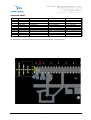
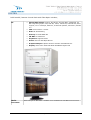
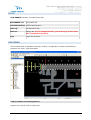
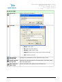
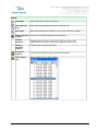
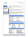
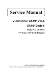
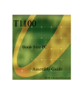
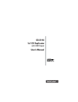
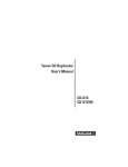
RCD-2000FX
RUNWAY LIGHTING
REMOTE CONTROL DESK
with
FIBER OPTIC
Version 2.0
USER MANUAL
Published by
Teksav Teknoloji Elektrik Elektronik Mak. Sanayi ve Tic.
A.Ş.
Address
Phone
Fax
e-Mail
Web Site
:10016 Sokak No: 20 A.O.S.B. Cigli Izmir – Turkey
: +90-232-3281141 (PBX 5 lines)
: +90-232-3281147
: [email protected] [email protected]
: www.teksav-teknoloji.com
Document no
Date
Manufacturer NATO code
DUNS no
: 060817-4
: November 2006
: T9041
: 566212869
TEKSAV Teknoloji A.S
certified according to
ISO 9001:2008
Copyright©2009 Teksav Teknoloji A.S All rights reserved.
RCD-2000FX, User Manual
1
REVISION SHEET
#
1
2
3
4
5
Date
May 2006
July 2006
Aug 2006
Nov 2006
March 2010
Description
Modification
Modification
Modification
upgrading
Done by
Yavuz Özdemir
Yavuz Özdemir
Yavuz Özdemir
Yavuz Özdemir
P. Akdurak
Approved by
Dr. S. Akdurak
Dr. S. Akdurak
Dr. S. Akdurak
Dr. S. Akdurak
Dr. S. Akdurak
All changes to this document have to be recorded to the revision sheet.
RCD-2000FX, User Manual
2
INDEX
MAIN WINDOW..........................................................................................................4
SETTINGS.................................................................................................................5
PASSWORD...............................................................................................................5
CHANGE PASSWORD..................................................................................................5
SYSTEM....................................................................................................................6
System Design....................................................................................................... 7
Runtime Configuration.............................................................................................8
IP and Mask Assignment..........................................................................................8
SERVICE...................................................................................................................9
Buttons and service modes...................................................................................... 9
FILES......................................................................................................................10
DESIGNER...............................................................................................................10
CCR (Constant Current Regulator)...........................................................................10
CELL....................................................................................................................11
Lights.................................................................................................................. 11
Working Modes..................................................................................................... 11
Buttons................................................................................................................12
Files.................................................................................................................12
Cells.................................................................................................................13
Groups & CCRs..................................................................................................14
Lights...............................................................................................................15
Alignment.........................................................................................................16
Selection.......................................................................................................... 16
PopUp Menu......................................................................................................16
CONTROL................................................................................................................ 17
Control Menu........................................................................................................18
RCD-2000FX, User Manual
3
MAIN WINDOW
By this module, you can define all system parameters and run design and control module.
touch screens , user friendly control is guaranteed
The master PC is showing on the left upper corner, the used PC is showing on the right
bottom corner.
Management menu includes below items.
Settings
Sets serial (com) port for the switchs and system name.
Change Password
Changes the system password.
Service
Runs the Service Module.
Designer
Runs the Designer Module.
Control
Runs the Control Module.
RCD-2000FX, User Manual
4
Exit
Exits the software.
SETTINGS
Com Port for Swithes
Sets serial (com) port for the switchs.
System Name
Sets the system name that showing control module.
PASSWORD
System is under protection for entering by unauthorized people without password. The
password is case sensitive. After three wrong trails software will stop.
CHANGE PASSWORD
The system will start existing password which have been logged by the manufacturer. You
can create your own password should be at least 4 characters up 15. Retype your new
password.
RCD-2000FX, User Manual
5
SYSTEM
RCD-2000FX, Remote Control Desk with Fiber Optic includes;
PC
Media
Converter
•
Shuttle XPC SS59G: LGA775, Sis 661FX, 500/533 MHz, 2xDDR400, 64
MB integrated graphic card, AGP 8X, 1xPCI, 1xATA133, 2xSerial ATA, Raid
support, I.C.E. Heat Pipe, Ethernet, 6 channels speaker, 2xFirewire, 6xUSB
2.0
•
CPU: Intel Celeron 3.2 MHz
•
Disk: 80 GB Samsung
•
Memory: 512 MB DDR 400
•
CD-RW: LG 52x32x52
•
Keyboard: Logitech Media
•
Mouse: A4 Tech 620 Optic Mouse
•
Graphics Adaptor: Sparkle GeForce FX5200 128 MB DDR+TV
•
Display: View Sonic VA1912W Wide MultiMedia Digital LCD
Allied Telesyn AT-MC102XL: 100Base-TX to 100Base-FX Fast Ethernet Converter
RCD-2000FX, User Manual
6
Ethernet to
Serial
Converter
MOXA 4110S, Ethetnet to Serial (RS232) Converter
Ethernet
Switch
Allied Telesyn AT-FS708 Fast Ethernet Switch
Fiber Cable
HCS, Armored Single Loose Tube Fiber Optic Cables, Black, 62.5/125 micron, 4
cores
Patch Panel
HSC Multimedia Box
System Design
RCD-2000FX, User Manual
7
Runtime Configuration
The minimum configuration of RCD-2000FX is listed below:
•
1440 x 900 pixels Screen Resolution
•
Highest (32 bit) Color quality
•
Fast ethernet
•
Microsoft Windows XP with Service Pack 2
•
5 MB free disk space (except log files)
•
Graphic Card with 64 MB
IP and Mask Assignment
IP and Mask assignments listed below:
Hardware
IP
Mask
Name
Tower Computer
192.168.1.2
255.255.255.0
RCD1
Shelter Computer
192.168.1.3
255.255.255.0
RCD2
Other Computers
192.168.1.x
x: 4..99
255.255.255.0
RCDy
y:3..99
Cell (Moxa)
192.168.1.100
255.255.255.0
Other Cells
192.168.1.z
z: 101..150
255.255.255.0
RCD-2000FX, User Manual
8
SERVICE
This module checks the selected cell’s CCRs and switches.
Buttons and service modes
Setup
Setup the service parameters.
Start
Start the service process.
Stop
Stop the service process.
Service
Modes
•
Normal Mode: Query the cell CCRs only. If you set the channel,
please click gray circle.
•
Test Mode: System automatically sets the CCR channels to all
levels in sequentially.
•
Random Mode: System automatically sets the CCR channels to
random level.
•
Full Mode: System automatically sets the CCR channels to full
level.
RCD-2000FX, User Manual
9
FILES
RCD-2000FX software includes below files.
RCD2000FX.exe
Executable file.
airfield1400.bmp Airfield base picture.
Data.cfg
Configuration file.
Data.tre
Design file. If you change this file, you must copy it into other
PCs' installation directory.
Logs
Logs' file directory.
DESIGNER
This module helps to operation designer relation, configuration, location and defining
between cell room, CCRs and lights.
CCR (Constant Current Regulator)
System has control card for each CCR.
RCD-2000FX, User Manual
10
CELL
Each CCR group separately controlled.
Lights
Each lighting fixture is called light. Lighting fixture symbols:
Runway Edge
Taxiway Edge
Approach
Threshold
Papi
Reil
Rotating Beacon
WindCone
Runaway Distance Marker
Strope Light
Working Modes
System includes three different working modes.
•
Add Light: Click your mouse anywhere that you want to add light for selected CCR.
•
Add Lights by Line: This option is used to locate lights on selected line. Follow the
below procedure to create a lights line:
o
o
o
o
•
Select the light fixture symbol from the light list.
Click you mouse at the beginning of line and move your mouse to the end
point by pushing left mouse key. You can also use Shift and Ctrl key for
horizontal or vertical line.
Relese the left mouse key.
Write the quantity of lights on opening window and click OK button.
Edit Mode: This option used for changing and location of light fixture group. Follow
the below procedure to create a lights line:
o
Click your mouse left key on any corner of lights group and select the lights,
draw the mouse while left key pressed. Release the left key when all fixture
are selected which needed to change.
Click on unselected lights by pressing shift key for adding to the list
o
Click on any selected light by pressing shift key for removing from the list.
o
Click your mouse on any clean place to cancel your selection.
RCD-2000FX, User Manual
11
Buttons
Files
Load
Design File
Loads and shows the design parameters from the file.
Save
Design File
Saves design parameters to the file.
Compile
and Check
Integrity
Compiles and checks the design parameters.
Show
Active
Mode
Generates active mode presentation from design parameters.
Connection
Report
Generates connection report between Lights, Control Cards, CCRs,
Cells, and Switch.
Export
Lights List
Exports all lights to user file.
Exit
Exits the design module.
RCD-2000FX, User Manual
12
Cells
Add Cell
Adds new cell to designer.
•
Name: Cell name
•
IP Address: Preconfigured Cell Control Card IP address.
•
Check IP: Search network (Moxa) device for the defined
IP.
Edit Selected Cell
Changes the parameters of the selected cell.
Delete Selected
Cell
Deletes the selected cell.
RCD-2000FX, User Manual
13
Groups & CCRs
Add Group
Adds new group to designer.
Add CCR
Adds new CCR to the selected group.
•
Name: CCR name
•
ID: CCR's control card ID.
•
Switch: CCR's switch name
•
Channel: Connected control card channel settings.
•
Cell: CCR'S cell name.
Edit Selected
Group/CCR
Changes the parameters of the selected group or CCR.
Delete Selected
Group/CCR
Deletes the selected group or CCR and than if you want, clear
the CCR assignment.
Show Selected
CCR's Light
Shows and selects the lights of the selected CCR.
RCD-2000FX, User Manual
14
Lights
Add Light
Adds new light to the clicked point.
Add Lights by
Line
Adds equal spaced lights along the defined line.
Edit Light
Edits light parameters (position, CCR, type, direction, width).
Delete Selected
Light(s)
Deletes the selected light(s) from designer.
Change
Direction
Changes light direction from left to right or right to left
(applicable only strope, approach, threshold, wind cone)
Change
Selected
Light(s)
Changes the selected light type.
Set CCR to
Light(s)
Connects the selected CCR to the selected light.
Show Lights
List
Shows lights list in a new window.
RCD-2000FX, User Manual
15
Alignment
Align Left Edge
Aligns the selected lights to the left edge of the light first
selected.
Align Top Edge
Aligns the selected lights to the top edge of the light first
selected.
Space Equally,
Horizontally
Horizontally aligns three or more selected lights so that the
middle lights are equally spaced between the outer lights.
Space Equally,
Vertically
Vertically aligns three or more selected lights so that the
middle lights are equally spaced between the outer lights.
Dublicate
Dublicates the selected light(s).
Mirror
Mirrors the selected lights.
Flip
Flips the selected lights.
Selection
Select All
Selects all lights.
Invert
Selection
Selects the unselected lights, unselects the selected lights.
UnSelect All
Unselects all lights
PopUp Menu
You can reach to popup menu by clicking your mouse
right key. Available options will be seen as active others
passive.
RCD-2000FX, User Manual
16
CONTROL
This module is used for online control of all functions.
The up side of the window includes PC name, master PC name, date, time and control
button.
At the bottom side, Operation mode and lights information are seen. Default operation
mode is Switch. Operation modes are Switch, PC USER or Switch/PC.
Select the light brightness level using top bar
number 1, 2, 3, 4, 5. Click <ALL> if you want to
select all CCRs.
RCD-2000FX, User Manual
17
Control Menu
Control menu includes general control buttons:
Stop Control: This is just for master PC. It stops master PC
operation.
Set as Master: This is for changing client PC as master PC while
this changing process system will be off 15 seconds.
Refresh: the monitoring information from CCRs.
System Test: Testing all units’ conditions and operation levels.
System can control itself, relation with other PCs and all CCRs,
connection lines. In case any fault a yellow&red blinks. Select
system test option and test the system.
Show Log: Checking daily operation info and reports
RCD-2000FX, User Manual
18
Close All Others: All Client PCs closed by Master PC.
RCD-2000FX, User Manual
19
RCD-2000FX, User Manual
20
RCD-2000FX, User Manual
21