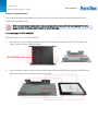
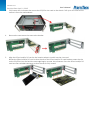
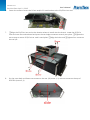
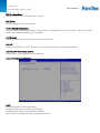
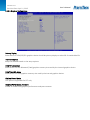
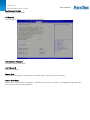
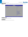
1
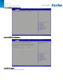
Version 1.0 Revision Date: April .1, 2015 User’s Manual User’s Manual PER535A Fanless Rugged system User’s Manual Version 1.0 Revision Date: April .1, 2015 Safety information User’s Manual User’s Manual Electrical safety To prevent electrical shock hazard, disconnect the power cable from the electrical outlet before relocating the system. When adding or removing devices to or from the system, ensure that the power cables for the devices are unplugged before the signal cables are connected. If possible, disconnect all power cables from the existing system before you add a device. Before connecting or removing signal cables from the motherboard, ensure that all power cables are unplugged. Seek professional assistance before using an adapter or extension cord. These devices could interrupt the grounding circuit. Make sure that your power supply is set to the correct voltage in your area. If you are not sure about the voltage of the electrical outlet you are using, contact your local power company. If the power supply is broken, do not try to fix it by yourself. Contact a qualified service technician or your local distributor. Operation safety Before installing the motherboard and adding devices on it, carefully read all the manuals that came with the package. Before using the product, make sure all cables are correctly connected and the power cables are not damaged. If you detect any damage, contact your dealer immediately. To avoid short circuits, keep paper clips, screws, and staples away from connectors, slots, sockets and circuitry. Avoid dust, humidity, and temperature extremes. Do not place the product in any area where it may become wet. Place the product on a stable surface. If you encounter any technical problems with the product, contact your local distributor Statement All rights reserved. No part of this publication may be reproduced in any form or by any means, without prior written permission from the publisher. All trademarks are the properties of the respective owners. All product specifications are subject to change without prior notice Version 1.0 Revision Date: April .1, 2015 Revision History Revision V1.0 Date (yyyy/mm/dd) 2015/04/1 User’s Manual User’s Manual Changes Initial release Packing list □ PER535A Fanless Rugged System □ CD (Driver + User’s Manual) □ 19V, 120W, AC/DC power adapter w/o power cord (0 to 40°C, FSP) optional □ 24V, 160W, AC/DC power adapter w/o power cord (-30 to 70°C, Meanwell) optional Accessories Kit □ Wall mount bracket x 2pcs □ Terminal block 3 PIN x 1pcs □ Screw kit (For 2.5” device x 8pcs, For Wall mount x 6pcs) □ Thermal Pad x 1pcs (For CPU) If any of the above items is damaged or missing, please contact your local distributor. Ordering information Model Number Description PER535A-ET Intel® QM77 Fanless Rugged System with Intel® Ivy Bridge Core™ i7/i5/i3 Processor, with 1xPCI & 1x PCIe Expansion, 9V to 24V DC-in, Wide Temp. (-20 to 60°C) PER535A-UT Intel® QM77 Fanless Rugged System with Intel® Ivy Bridge Core™ i7/i5/i3 Processor, with 1xPCI & 1x PCIe Expansion, 9V to 24V DC-in, Wide Temp. (-40 to 70°C, optional) Processor Intel® Core™ i7-3610QE Processor (6M Cache, 2.30 GHz), 45 W Intel® Core™ i5-3610ME Processor (3M Cache, 2.70GHz), 35W Intel® Core™ i3-3120ME Processor (3M Cache, 2.40 GHz), 35W Version 1.0 Revision Date: April .1, 2015 Table of contents User’s Manual User’s Manual SAFETY INFORMATION ........................................................................................................................................ 2 ELECTRICAL SAFETY..................................................................................................................................................... 2 OPERATION SAFETY .................................................................................................................................................... 2 STATEMENT ......................................................................................................................................................... 2 REVISION HISTORY .............................................................................................................................................. 3 PACKING LIST ...................................................................................................................................................... 3 ACCESSORIES KIT ....................................................................................................................................................... 3 ORDERING INFORMATION................................................................................................................................... 3 TABLE OF CONTENTS ........................................................................................................................................... 4 CHAPTER 1: PRODUCT INTRODUCTION ............................................................................................................... 6 1.1 KEY FEATURES ..................................................................................................................................................... 6 1.2 FRONT PANEL COMPONENTS ................................................................................................................................. 7 1.3 BACK PANEL COMPONENTS ................................................................................................................................... 7 1.4 MECHANICAL DIMENSIONS.................................................................................................................................... 8 CHAPTER 2 CONNECTORS DEFINITIONS .............................................................................................................. 9 2.1 FRONT PANEL CONNECTOR PIN DEFINITIONS ........................................................................................................... 9 USB Port: USB2.0 .............................................................................................................................................. 9 COM2~COM3: RS232 with +12V/+5V selection ............................................................................................. 9 COM4: RS232 .................................................................................................................................................... 9 COM5: RS232/422/485 .................................................................................................................................... 9 STATUS INDICATORS .......................................................................................................................................... 10 2.2 REAR PANEL CONNECTOR PIN DEFINITIONS ........................................................................................................... 10 VGA: VGA ........................................................................................................................................................ 10 DVI-D: DVI-D ................................................................................................................................................... 10 HDMI: HDMI ................................................................................................................................................... 10 LAN1_USB12: USB3.0 port 0,1 and LAN connector 1................................................................................... 11 LAN2_USB34: USB3.0 port 3,4 and LAN connector 2................................................................................... 11 AUDIO1: LINE-OUT/LINE-IN/MIC-IN .............................................................................................................. 11 COM1: RS232/422/485 with +12V/+5V selection ........................................................................................ 12 Power Input: DC-in +9V~+24V ....................................................................................................................... 12 CHAPTER 3: GETTING STARTED ......................................................................................................................... 13 3.1 INSTALLING A 2.5" SATA HDD/SSD .................................................................................................................... 13 3.2 INSTALLING PCI CARD AND PCIE X1 CARD .............................................................................................................. 14 CHAPTER 4: AMI BIOS UTILITY ........................................................................................................................... 17 4.1 STARTING ......................................................................................................................................................... 17 4.2 NAVIGATION KEYS .............................................................................................................................................. 17 4.3 MAIN MENU .................................................................................................................................................... 18 4.4 ADVANCED MENU ............................................................................................................................................. 19 Version 1.0 Revision Date: April .1, 2015 User’s Manual 4.4.1 ACPI Settings ......................................................................................................................................... 20 User’s Manual 4.4.2 CPU Configuration ................................................................................................................................. 21 4.4.3 SATA Configuration ................................................................................................................................ 23 4.4.4 Thermal Configuration .......................................................................................................................... 24 4.4.4.1 Platform thermal configuration ................................................................................................... 24 4.4.5 Intel Rapid Start Technology ................................................................................................................. 25 4.4.6 Intel TXT(LT) Configuration ................................................................................................................... 25 4.4.7 PCH-FW Configuration .......................................................................................................................... 26 4.4.8 Intel Anti-Theft Technology Configuration ........................................................................................... 26 4.4.9 AMT Configuration ................................................................................................................................ 27 4.4.10 USB Configuration ............................................................................................................................... 28 4.4.11 F81866 Super IO Configuration .......................................................................................................... 29 4.4.12 F81866 H/W Monitor ......................................................................................................................... 30 4.4.13 Serial Port Console Redirection .......................................................................................................... 31 4.4.14 CPU PPM Configuration ...................................................................................................................... 32 4.5 CHIPSET ........................................................................................................................................................... 33 4.5.1 PCH-IO Configuration ............................................................................................................................ 33 4.5.1.1 USB Configuration ......................................................................................................................... 34 4.5.1.2 PCH Azalia Configuration .............................................................................................................. 35 4.5.2 System Agent (SA) Configuration ......................................................................................................... 36 4.5.2.1 Graphics Configuration ................................................................................................................. 37 4.5.2.2 Memory Configuration ................................................................................................................. 38 4.6 BOOT SETTING .................................................................................................................................................. 39 4.7 SECURITY .......................................................................................................................................................... 40 4.8 SAVE AND EXIT ................................................................................................................................................... 41 Version 1.0 Revision Date: April .1, 2015 User’s Manual Chapter 1: Product Introduction User’s Manual 1.1 Key Features System CPU Chipset Ethernet Chipset Memory Expansion Slot Storage Device Front I/O Power Button Power LED HDD LED COM Intel® 22nm Ivy Bridge Processor (Mobile) socket (rPGA988) Core™ i7-3610QE 2.3 GHz (6M Cache, 45W) Core™ i5-3610ME 2.7 GHz (3M Cache, 35W) Core™ i3-3120ME 2.4 GHz (3M Cache, 35W) Intel® QM77 Intel® 82579LM & 82574IT GbE 2 x 204-pin SO-DIMM support up to 16 GB dual channel DDR3 1333/1600, Non-ECC 1 x Mini-PCIe 1 x PCI 1 x PCIe x1 2 x 2.5" SATA HDD/SSD 1 Green color Red color 2 x RS232/with 5V/12V selectable 1 x RS232 1 x RS232/422/485 4 x USB 2.0 USB Rear I/O VGA 1 DVI-D 1 HDMI 1 Ethernet 2 x RJ45 Audio Mic-in, Line-in, Line-out COM 1x RS232/422/485 with 5V/12V selectable USB 4 x USB 3.0 Antenna Reserved two antenna holes Power Input 9V to 24V DC-in (by terminal block) Mechanical & Environment Power Requirements 9V to 24V DC-in Dimension 370 x 122 x 246 mm (W x H x D) (14.57" x 4.8" x 9.69") Operating Temp. -40 to 70°C (ambient with air flow) Storage Temp. -20 to 80°C Relative Humidity 10% to 90%, non-condensing *Specifications are subject to change without notice* Version 1.0 Revision Date: April .1, 2015 1.2 Front Panel Components 1 2 3 4 Power Button Power LED, HDD LED 4 x USB 2.0 2 x RS232/with 5V/12V selectable 1 x RS232 1 x RS232/422/485 1.3 Back Panel Components 1 2 3 4 5 6 7 8 9, 10 11 12 Power Input 9V to 24V DC-in (by terminal block) DVI-D port VGA port COM port, RS232/422/485 with 5V/12V selectable HDMI port 4 x USB 3.0 LAN port, 2 x RJ45 Audio jack (Mic-in, Line-in, Line-out) Antenna holes Expansion slot (PCI) Expansion slot (PCIe x1) User’s Manual User’s Manual Version 1.0 Revision Date: April .1, 2015 1.4 Mechanical Dimensions User’s Manual User’s Manual Version 1.0 Revision Date: April .1, 2015 User’s Manual Chapter 2 Connectors definitions User’s Manual This chapter describes the connectors on the systems 2.1 Front Panel Connector Pin Definitions USB Port: USB2.0 PIN DEFINITION 1 +5V 2 USBD3 USBD+ 4 GND PIN 5 6 7 8 DEFINITION +5V USBDUSBD+ GND COM2~COM3: RS232 with +12V/+5V selection PIN DEFINITION PIN DEFINITION 1 DCD2 RXD 3 TXD 4 DTR5 GND 6 DSR7 RTS8 CTS9 COM2P9SEL/ COM3P9SEL (Define by JP6/7) COM4: RS232 PIN DEFINITION 1 DCD3 TXD 5 GND 7 RTS9 RI- PIN 2 4 6 8 DEFINITION RXD DTRDSRCTS- COM5: RS232/422/485 PIN RS-232 RS-422 1 DCDTX2 RXD RX+ 3 TXD TX+ 4 DTRRX5 GND GND 6 DSRNA 7 RTSNA 8 CTSNA 9 RIRI- HALF DUPLEX RS-485 DATANA DATA+ NA GND NA NA NA RI- Version 1.0 Revision Date: April .1, 2015 Status Indicators STATUS HDD PWR User’s Manual LED COLOR Red Green 2.2 Rear Panel Connector Pin Definitions VGA: VGA PIN DEFINITION 1 RED 2 GREEN 3 BLUE 4 NC 5 GND 6 GND 7 GND 8 GND DVI-D: DVI-D PIN DEFINITION 1 TMDS22 TMDS2+ 3 GND 4 NC 5 NC 6 DDC_CLK 7 DDC_DATA 8 NC 9 TMDS110 TMDS1+ 11 GND 12 NC HDMI: HDMI PIN DEFINITION 1 HDMI_2P 2 GND 3 HDMI_2N 4 HDMI_1P 5 GND 6 HDMI_1N 7 HDMI_0P 8 GND 9 HDMI_0N 10 HDMI_CLKP User’s Manual PIN 9 10 11 12 13 14 15 DEFINITION +5V GND NC DDC DATA HSYNC VSYNC DDC CLOCK PIN 13 14 15 16 17 18 19 20 21 22 23 24 DEFINITION NC +5V GND HOTPLUG_DETECT TMDS0TMDS0+ GND NC NC GND TMDSCLK+ TMDSCLK- PIN 11 12 13 14 15 16 17 18 19 DEFINITION GND HDMI_CLKN NC NC DDC CLOCK DDC DATA GND +5V HOTPLUG_DETECT Version 1.0 Revision Date: April .1, 2015 LAN1_USB12: USB3.0 port 0,1 and LAN connector 1 LAN2_USB34: USB3.0 port 3,4 and LAN connector 2 UPPER USB LOWER USB LAN PIN DEFINITION PIN DEFINITION PIN DEFINITION 1 +5VDUAL 1 +5VDUAL 1 D0+ 2 D2 D2 D03 D+ 3 D+ 3 D1+ 4 GND 4 GND 4 D15 StdA_SSTX- 5 StdA_SSTX- 5 D2+ 6 StdA_SSTX+ 6 StdA_SSTX+ 6 D27 GND_DRIAN 7 GND_DRIAN 7 D3+ 8 StdA_SSRX- 8 StdA_SSRX- 8 D39 StdA_SSRX- 9 StdA_SSRXSPEED LED: (LIFT) ACTIVE LED: (RIGHT) GREEN: 1000Mbps ORANGE (BLINKING): ACTIVITY ORANGE: 100Mbps No Light: NOT LINK No Light: 10Mbps ORANGE (NO BLINKING): LINK AUDIO1: LINE-OUT/LINE-IN/MIC-IN PIN DEFINITION 1 LINE-IN 2 LINE-OUT 3 MIC_IN User’s Manual User’s Manual Version 1.0 Revision Date: April .1, 2015 COM1: RS232/422/485 with +12V/+5V selection PIN RS-232 RS-422 HALF DUPLEX RS-485 1 DCDTXDATA2 RXD RX+ NA 3 TXD TX+ DATA+ 4 DTRRXNA 5 GND GND GND 6 DSRNA NA 7 RTSNA NA 8 CTSNA NA 9 COM1P9SEL COM1P9SEL COM1P9SEL (Define by JP5) (Define by JP5) (Define by JP5) Power Input: DC-in +9V~+24V PIN DEFINITION 1 +9V~+24V 2 3 GND User’s Manual User’s Manual Version 1.0 Revision Date: April .1, 2015 Chapter 3: Getting Started User’s Manual User’s Manual This chapter provides more detailed information and let you know how to install components into the PER535A embedded System. Prior to removing the chassis cover, make sure the unit’s power is off and disconnected from the power sources to prevent electric shock or system damage. 3.1 Installing a 2.5" SATA HDD/SSD PER535A supports 2 x 2.5" SATA HDD/SSD 1. Remove four screws of SATA HDD/SSD cover on the back side of the chassis. Take off the cover, the cover is used to hold the SATA HDD/SSD. 2. There are eight screws in the accessory packet. Slide the SATA HDD/SSD into the SATA HDD/SSD cover, align with the mounting holes and fasten the screws. Version 1.0 Revision Date: April .1, 2015 3. User’s Manual Plug in the SATA cable and turn the SATA HDD/SSD cover back to the chassis fasten the four screws User’sand Manual on the back side. 3.2 Installing PCI card and PCIe x1 card The PER535A supports 1 x PCI and 1 x PCIe x1 expansion slot 1. Remove two screws on the rear I/O (screw 1, 2) and two screws on the top of PER535A (screw 3, 4), then slide the cover to take it off. 2. Locate the PCI/PCIe riser card inside of the PER535A Version 1.0 Revision Date: April .1, 2015 User’s Manual 3. Fully loosen the six screws that secure the PCI/PCIe riser card to the chassis. up on the riser card to User’sPull Manual unseat it from the motherboard. 4. Remove the two screws that secure the bracket 5. Align the PCIex1 and/or PCI card to the location where it installs into the riser card. Rotate the PCIex1 and/or PCI card so that the tab of the PCIex1 and/or PCI card bracket enters the slot on the PCI/PCIe riser card and the card edge begins to enter the connector. Press the PCIex1 and/or PCI card into the card edge connector so that the card is fully seated. Version 1.0 Revision Date: April .1, 2015 User’s Manual 6. Fasten the screw to secure the PCIex1 and/or PCI card bracket to the PCI/PCIe riser card. User’s Manual 7. ①Align the PCI/PCIe riser card to the location where it installs into the chassis. Lower the PCI/PCIe riser card onto the motherboard and press the card edge connector securely into place. ②Tighten the two screws to secure PCI/PCIe riser card’s metal plate. ③Align the holes and ④tighten four screws on the real I/O. 8. Put the cover back and fasten two screws on the rear I/O (screw 1, 2) and two screws on the top of PER535A (screw 3, 4) Version 1.0 Revision Date: April .1, 2015 Chapter 4: AMI BIOS UTILITY User’s Manual User’s Manual This chapter provides users with detailed descriptions on how to set up a basic system configuration through the AMI BIOS setup utility. 4.1 Starting To enter the setup screens, perform the following steps: Turn on the computer and press the <Del> key immediately. After the <Del> key is pressed, the main BIOS setup menu displays. Other setup screens can be accessed from the main BIOS setup menu, such as the Chipset and Power menus. 4.2 Navigation Keys The BIOS setup/utility uses a key-based navigation system called hot keys. Most of the BIOS setup utility hot keys can be used at any time during the setup navigation process. Some of the hot keys are <F1>, <F10>, <Enter>, <ESC>, and <Arrow> keys. Some of the navigation keys may differ from one screen to another. Left/Right Up/Down +− Plus/Minus Tab F1 F10 Esc Enter The Left and Right <Arrow> keys moves the cursor to select a menu. The Up and Down <Arrow> keys moves the cursor to select a setup screen or sub-screen. The Plus and Minus <Arrow> keys changes the field value of a particular setup setting. The <Tab> key selects the setup fields. The <F1> key displays the General Help screen. The <F10> key saves any changes made and exits the BIOS setup utility. The <Esc> key discards any changes made and exits the BIOS setup utility. The <Enter> key displays a sub-screen or changes a selected or highlighted option in each menu. Version 1.0 Revision Date: April .1, 2015 User’s Manual 4.3 Main Menu User’s Manual The Main menu is the first screen that you will see when you enter the BIOS Setup Utility. Version 1.0 Revision Date: April .1, 2015 System Language Use this function to select the system language. User’s Manual User’s Manual System Date Use this function to change the system date. Select System Date using the Up and Down <Arrow> keys. Enter the new values through the keyboard. Press the Left and Right <Arrow> keys to move between fields. The date setting must be entered in MM/DD/YY format. System Time Use this function to change the system time. Select System Time using the Up and Down <Arrow> keys. Enter the new values through the keyboard. Press the Left and Right <Arrow> keys to move between fields. The time setting is entered in HH:MM:SS format. Note: The time is in 24-hour format. For example, 5:30 A.M. appears as 05:30:00, and 5:30 P.M. as 17:30:00. Access Level Displays the access level of the current user in the BIOS. 4.4 Advanced Menu The Advanced Menu allows you to configure your system for basic operation. Some entries are defaults required by the system board, while others, if enabled, will improve the performance of your system or let you set some features according to your preference. Setting incorrect field values may cause the system to malfunction. Version 1.0 Revision Date: April .1, 2015 4.4.1 ACPI Settings System ACPI parameters User’s Manual User’s Manual Enable ACPI Auto Configuration Enables or disables BIOS ACPI auto configuration. Enable Hibernation Enables or disables system ability to hibernate (OS/S4 Sleep State). This option may not be effective with some OS. ACPI Sleep State Select the ACPI sleep state the system will enter when the suspend button is pressed. Lock Legacy Resources Enables or Disables System Lock of Legacy Resources. S3 Video Repost Enable or disable S3 Video Repost. Version 1.0 Revision Date: April .1, 2015 4.4.2 CPU Configuration This section is used to configure the CPU. User’s Manual User’s Manual Version 1.0 Revision Date: April .1, 2015 User’s Manual Hyper-threading User’s Manual Enabled for Windows XP and Linux (OS optimized for Hyper-Threading Technology) and Disabled for other OS (OS not optimized for Hyper-Threading Technology). When disabled only one thread per enabled core is enabled. Active Processor Cores Number of cores to enable in each processor package. Limit CPUID Maximum Disabled for Windows XP. Execute Disable Bit XD can prevent certain classes of malicious buffer overflow attacks when combined with a supporting OS (Windows Sever 2003 SP1, Windows XP SP2, SuSE Linux 9.2, RedHat Enterprise 3 Update 3.) Intel Virtualization Technology When enabled, a VMM can utilize the additional hardware capabilities provided by Vanderpool Technology. Hardware Prefetcher To turn on/off the Mid Level Cache (L2) streamer prefectcher Adjacent Cache Line Prefetche To turn on/off prefectching of adjacent cache lines TCC Activation Offset Offset from the factory TCC activation temperature Primary Plane Current Value The Maximum instantaneous current allow for primary plane Secondary Plane Current Value The Maximum instantaneous current allow for secondary plane Version 1.0 Revision Date: April .1, 2015 4.4.3 SATA Configuration This section is used to configure the SATA drives. SATA Controller(s) Enable or disable SATA device. SATA Mode Selection Determines how SATA controller(s) operate. SATA Test Selection Enable or disable Test Mode IDE Legacy/Native Mode Selection IDE Legacy/Native Mode Selection Serial ATA Port 0 – 5 Displays information on the SATA devices detected User’s Manual User’s Manual Version 1.0 Revision Date: April .1, 2015 4.4.4 Thermal Configuration Platform thermal configuration options 4.4.4.1 Platform thermal configuration User’s Manual User’s Manual Version 1.0 Revision Date: April .1, 2015 User’s Manual 4.4.5 Intel Rapid Start Technology User’s Manual 4.4.6 Intel TXT(LT) Configuration Intel Trusted Execution Technology Intel TXT(LT) Support Enables or disables Intel TXT(LT) support Version 1.0 Revision Date: April .1, 2015 User’s Manual 4.4.7 PCH-FW Configuration User’s Manual This section is used to configure Management Engine Technology parameters. 4.4.8 Intel Anti-Theft Technology Configuration Disabling Intel AT allow user to login platform. This is strictly for testing only. This does not disable Intel AT services in ME Version 1.0 Revision Date: April .1, 2015 Intel Anti-Theft Technology Enable or Disable Intel AT in BIOS for testing only User’s Manual User’s Manual Intel Anti-Theft Technology Rec Set the number of times Recovery attemped will be allowed. 4.4.9 AMT Configuration This section is used to configure Active Management Technology (AMT) options. Intel AMT Enable/disables Intel Active Management Technology BIOS extension. Note: iAMT H/W is always enabled. This option just controls the BIOS extension execution. If enabled, this requires additional firmware in the SPI device. BIOS Hotkey Pressed Enable/disable BIOS hotkey press. MEBx Selection Screen Enable/disable MEBx Selection Screen Hide Un-Configure ME Confirmation Hide Un-Configure ME without password confirmation prompt MEBx Debug Message Screen Enable MEBx debug message output Un-Configure ME Perform AMT/ME unconfigure without password operation. Version 1.0 Revision Date: April .1, 2015 Amt Wait Timer Set timer to wait before sending ASF_GET_BOOT_OPTIONS. Disable ME Set ME to Soft Temporary Disabled ASF Enable/Disable Alert specification Format Activate Remote Assistance Process Trigger CIRA boot. USB Confirgure Enable/Disable USB configure function. PET Progress User can Enable/Disable PET Events progress to receive PET events or not. Watchdog Timer Enable/Disable Watchdog Timer. 4.4.10 USB Configuration This section is used to configure the USB Legacy USB Support Enables Legacy USB support. AUTO option disables legacy support if no USB devices are connected. DISABLE option will keep USB devices available only for EFI applications. User’s Manual User’s Manual Version 1.0 Revision Date: April .1, 2015 USB3.0 Support Enable/Disable USB3.0 (XHCI) Controller support. User’s Manual User’s Manual XHCI Hand-off This is a workaround for OSes without XHCI hand-off support. The XHCI ownership change should be claimed by XHCI driver. EHCI Hand-off This is a workaround for OSes without EHCI hand-off support. The EHCI ownership change should be claimed by EHCI driver. Port 64/60 Emulation Enables I/O port 60h/64h emulation support. This should be enabled for the complete USB keyboard legacy support for non-USB aware OSes. USB Transfer time-out The time-out value for Control, Bulk, and Interrupt transfers. Device reset time-out USB mass Storage device start Unit command time-out. Device power-up delay Maximum time the device will take before it properly reports itself to the Host Controller. ‘Auto’ uses default value: for a Root port it is 100ms, for a Hub port the delay is taken from Hub descriptor. 4.4.11 F81866 Super IO Configuration System super IO chip parameters Version 1.0 Revision Date: April .1, 2015 User’s Manual Serial Port Configuration User’s Manual Set Parameters of Serial Ports. User can Enable/Disable the serial port and Select an optimal settings for the Super IO Device. Parallel Port configuration Set parameters of parallel port (LPT/LPTE) 4.4.12 F81866 H/W Monitor This section is used to monitor hardware status such as temperature, fan speed and voltages. System Temperature Detects and displays the current system temperature. CPU Temperature Detects and displays the current CPU temperature. Fan1/2 Speed Detects and displays the current CPU fan speed. Version 1.0 Revision Date: April .1, 2015 User’s Manual 4.4.13 Serial Port Console Redirection User’s Manual This screen provides information about functions for specifying the Serial Port Console Redirection configuration settings. Console redirection can be used to remotely operate system settings and the EFI console. Console Redirection Console Redirection Enable or Disable. Console Redirection Settings The setting specify how the host computer and the remote computer (which the user is using) will exchange data. Both computers should have the same or compatible settings. Version 1.0 Revision Date: April .1, 2015 User’s Manual 4.4.14 CPU PPM Configuration CPU PPM configuration parameters User’s Manual EIST Enables or disables Intel SpeedStep. CPU C3 Report Enable or disable CPU C3 (ACPI C2) report to OS. Config TDP LOCK Lock the Config TDP control register Long duration power limit Long duration power limit in Watts, 0 means use factory default. Long duration maintained Time window which the long duration power is maintained. Short duration power limit Short duration power limit in Watts, 0 means use factory default. ACPI T State Enable or disable ACPI state support. Version 1.0 Revision Date: April .1, 2015 User’s Manual 4.5 Chipset User’s Manual This section gives you functions to configure the system based on the specific features of the chipset. The chipset manages bus speeds and access to system memory resources. 4.5.1 PCH-IO Configuration This section allows you to configure the North Bridge Chipset. USB Configuration USB configuration settings Version 1.0 Revision Date: April .1, 2015 User’s Manual PCH Azalia Configuration PCH Azalia configuration settings User’s Manual PCH LAN Controller Enable or disable onboard NIC. Wake on LAN Enable or disable integrated LAN to wake the system. (The Wake On LAN cannot be disabled if ME is on at Sx state.) PCIE LAN Controller Enable or disable onboard PCIE LAN Wireless LAN Controller Enable or disable onboard MPCIE LAN-Wireless LAN. SLP_S4 Assertion Width Select a minimum assertion width of the SLP_S4# signal. Restore AC Power Loss Select AC power state when power is re-applied after a power failure. RI Wake Up RI wake up function select. Watch Dog Function select Watch Dog function enabled or disabled. 4.5.1.1 USB Configuration Version 1.0 Revision Date: April .1, 2015 XHCI Pre-Boot Driver Enable or disable XHCI Pre-Boot driver support. User’s Manual User’s Manual XHCI Mode Mode of operation of XHCI controller HS Port #1/2/3/4 Switchable Allows for HS port switching between xHCI and EHCI. If disabled, port is routed to EHCI. If HS port is routed to xHCI, the corresponding SS port is enabled. xHCI Streams Enable or disable xHCI Maximum Primary Stream Array Size. EHCI1/2 Control the USAB EHCI (USB 2.0) functions. One EHCI controller must always be enabled. USB Ports Per-Port Disable Control Control each of the USB ports (0~13) disabling. 4.5.1.2 PCH Azalia Configuration Azalia Control Detection of the Azalia device. Disabled=Azalia will unconditionally disabled. Enabled=Azalia will be unconditionally enabled. Auto=Azalia will enabled if present, disabled otherwise. Version 1.0 Revision Date: April .1, 2015 Azalia PME Enable or disable Power Management capability of audio controller. Azalia Internal HDMI codec Enable or disable internal HDMI codec for Azalia. 4.5.2 System Agent (SA) Configuration This section is used to configure the System Agent (SA) configuration. VT-d Check to enable VT-d function on MCH. Enable NB CRID Enable or disable NB CRID WorkAround. C-State Pre-Wake Controls C-State Pre-Wake feature for ARAT, in SSKPD[57]. Graphics Configuration Configure graphics settings Memory Configuration Memory configuration parameters User’s Manual User’s Manual Version 1.0 Revision Date: April .1, 2015 4.5.2.1 Graphics Configuration User’s Manual User’s Manual Primary Display Select which of IGFX/PEG/PCI graphics device should be primary display or select SG for switchable Gfx. Internal Graphics Keep IGD enabled based on the setup options. DVMT Pre-Allocated Select DVMT 5.0 Pre-Allocated (Fixed) graphics memory size used by the internal graphics device. DVMT Total Gfx Mem Select DVMT 5.0 total graphics memory size used by the internal graphics device. Gfx Low Power Mode This option is applicable for SFF only. Graphics Performance Analyzers Enable or disable Intel graphics performance analyzers counters. Version 1.0 Revision Date: April .1, 2015 4.5.2.2 Memory Configuration User’s Manual User’s Manual Version 1.0 Revision Date: April .1, 2015 4.6 Boot Setting This section is used to configure the boot features. User’s Manual User’s Manual Setup Prompt Timeout Number of seconds to wait for setup activation key. 65535(0xFFFF) means indefinite waiting. Bootup NumLock State Select the keyboard NumLock state. Quiet Boot Enables or Disables Quiet Boot option. Fast Boot Enables or Disables boot with initialization of a minimal set of devices required to launch active boot option. Has no effect for BBS boot options. GateA20 Active UPON REQUEST – GA20 can be disabled using BIOS services. ALWAYS – do not allow disabling GA20; this option is useful when any RT code is executed above 1MB. Option ROM Messages Set display mode for Option ROM. INT19 Trap Response BIOS reaction on INT19 trapping by Option ROM: IMMEDIATE – execute the trap right away; POSTPONED – execute the trap during legacy boot. Version 1.0 Revision Date: April .1, 2015 Boot Option Priorities Sets the system boot order. User’s Manual User’s Manual 4.7 Security Use the Security Menu to establish system passwords Administrator Password Set administrator password. User Password Set User Password. Secure Boot Secure boot flow control. Secure boot is possible only if system runs in user mode. Secure Boot Mode Secure boot mode selector. ‘Standard’ – fixed secure boot policy, ‘custom’ – changeable image execution policy and secure boot key databases. Version 1.0 Revision Date: April .1, 2015 User’s Manual 4.8 Save and exit User’s Manual This screen provides functions for handling changes made to the BIOS settings and the exiting of the Setup program. Save Changes and Exit Exit system setup after saving the changes. Restore Defaults Restore or Load Defaults values for all the setup options.