1
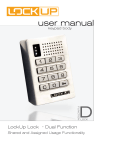
FUNCTION
M
LOCK
user manual
Multi Use Functionality - Keypad Lock
Table of Contents
Metal Door Installations___________________________________________ 2
Required Components___________________________________________ 3
Metal Door Mounting Types______________________________________ 4
Surface Mount Metal Door Installation___________________________ 5
Recessed Cup Metal Door Installation_ ___________________________ 7
3-Hole Lock Plug Removal_ ______________________________________ 9
Padlock Hasp Removal___________________________________________ 10
Programming Instructions_ ______________________________ 12
Lock Interface Overview_________________________________________ 13
Key Guide______________________________________________________ 13
To Add Optional Manager Key(s)__________________________________ 14
To Erase Optional Manager Key(s)_ _______________________________ 14
Express Programming___________________________________________ 15
Lost Manager Key or Forgotten Manager Code_____________________ 16
Assigned Use Instructions________________________________ 18
Operate with an Assigned User Code______________________________ 19
Operate with an Optional Registered ADA User Key_________________ 19
Operate with a Manager Code____________________________________ 20
Operate with an Optional Manager Key____________________________ 20
Change User Code with Existing User Code________________________ 21
Change User Code with Manager Code_____________________________ 21
Add or Change Optional User Key_________________________________ 22
Change Manager Code___________________________________________ 22
Troubleshooting________________________________________________ 24
Common Lock Indicators_________________________________________ 25
Lock Warning Indicators_________________________________________ 25
Battery Replacement____________________________________________ 26
Overall Dimensions_____________________________________________ 27
Contact Information____________________________________________ 28
i
Warranty
LIMITED WARRANTY
Security People, Inc., dba Digilock (the “Company”) warrants to the original purchaser the products manufactured by the
Company (the “Product”) to be free of defects in material and workmanship, provided: (i) The Company has been notified
of such defects within two years of purchase date and been given the opportunity of inspection by return of any alleged
defective Product to the Company, or its authorized distributor, free and clear of all liens and encumbrances,
transportation prepaid, accompanied by the statement of defects and proof of purchase; and (ii) the Product has not
been modified, abused, misused, or improperly installed, maintained, and/or repaired during such period; and (iii) such
defect has not been caused by corrosion, exposure to moisture, or ordinary wear and tear. Next lock products are not
designed or intended for exterior use or where exposed to moisture. Any exterior use where exposed to moisture is not
covered by any warranties and voids any warranties. Any resulting damage caused by direct exterior exposure or moisture is at the purchasers own risk.
This warranty does not cover any labor costs for installation, removal and/or re-installation of the product being serviced
or replaced under warranty. This warranty is strictly limited to product repair or replacement. This warranty does not
cover batteries, normal wear of parts and/or damage resulting from any of the following: improper installation, negligent
use or misuse of the product, use of improper voltage or current, use contrary to operating instructions, and/or disassembly, repair or alteration by any person other than the Company service personnel.
The Company will not evaluate warranted product without first obtaining a Return Merchandise Authorization (RMA)
number from the Company. Such returns must be prominently marked with the Return Merchandise Authorization number and shipped prepaid (return shipping is the responsibility of the end-user). Under no circumstance is the Company
liable for incidental or consequential damages. The Company makes no other warranty, and all implied warranties
including any warranty of merchantability or fitness for a particular purpose are limited to the duration of the expressed
warranty period as set forth above.
LIMIT ON LIABILITY
The Company’s maximum liability for any damages resulting from or caused by the Product, whether in contract, tort,
or otherwise is limited to the purchase price of the Product. In no event shall the company be liable for any incidental or
consequential damages of any nature arising from the sale or use of this Product, whether in contract, tort, or otherwise
by either use or purchase of the Product the user or purchaser agrees to this limit on the company’s liability.
Note: Should the Product be considered a consumer product as may be covered by the Magnusson Moss Federal Warranty
Act, please be advised that: (1) some states do not allow limitations on incidental or consequential damages or how long
an implied warranty lasts so that the above limitations may not fully apply; (2) this warranty gives specific legal rights, and
a buyer may also have other rights which may vary from state to state. For warranty service and shipping instructions,
contact the Company. The Company reserves the right to make changes in designs and specifications or to make additions
or improvements on its products without notice and without incurring any obligation to incorporate them on products
previously manufactured. The Company is not responsible for any modification, addition or alteration to our products by
others. Purchaser agrees to indemnify and hold Company harmless from all claims causes of actions, lawsuits, administrative
actions, and damages (except as covered by the express limited warranty as set forth above) including reasonable attorney fees and costs arising out of or pertaining to the Product.
ii
1
Metal Door Installations
Required Components
Metal Door Mounting Types
Surface Mount Metal Door Installation
Recessed Cup Metal Door Installation
3-Hole Lock Plug Removal
Padlock Hasp Removal
2
Required Components
Next Lock Parts
Note: Confirm that all lock parts are present. If there are damaged or missing parts contact your
Next Product Support Specialist.
1-Front Unit
1-Rear Unit
2-Locking Nuts
Optional-Back Plate
Required Tools
For lock installation
3/8” Socket
(deep socket required)
For padlock hasp removal
Phillips Screwdriver
Head Size #1 & #2
Warning: Do not use an electric screw gun during installation of the
lock unless equipped with a torque adjuster, which must be set on a
low torque setting. Otherwise, damage may be caused to the lock.
3
Hack Saw
Metal File
Metal Door Mounting Types
Next is compatible with a majority of industry standard 3-hole configuration, latch and handle
types. Some door types may need disassembly or modifications prior to installation.
Single Point Latch
Standard Lift
Recessed Cup with
Multi-Point Latch
Box Locker Padlock Hasp
Recessed Cup with
Single Point Latch
ADA Handle
Note: See page 10 for additional
modifications for this door type.
Note: See page 10 for additional
modifications for this door type.
4
Surface Mount Metal Door Installation Parts
A
B
C
1-Front Unit
Required Tools
1-Rear Unit
2-Locking Nuts
3/8” Socket
(deep socket required)
Surface Mount Metal Door Installation Steps
Note: Prior to installation the door must be clear of any obstructions. See page 9 for door prep.
Step 1
Step 2
Place the mounting screw posts of the front unit (A)
through the lock mounting holes on the front of the
door.
While holding the front unit (A) against the front of the
door, place the rear unit (B) against the rear face of the
door. Align the mounting holes with the mounting screw
posts from the front unit (A).
5
Step 3
Step 4
Slide the front unit (A) and rear unit (B) together
making sure that the pins of the rear unit align with the
front unit (A) connector.
Place the locking nuts (C) over the mounting screws
and tighten to secure the lock to the door.
NOTE: Do not touch the rear unit connector pins
(male connector) against any metal or other conductive
surfaces. This may short the batteries and cause
damage to the lock.
NOTE: An audible triple beep and three flashes of
the LED light indicate that the lock was connected
properly. If you do not hear these beeps, separate the
units, press the “C” button on the keypad and reconnect
the front and rear units on the door.
Step 5
Step 6
Test the operation several times (as indicated
below) while the door is open. Close the door and
test the unit again. Make sure there is no binding
between the bolt/latch and the door strike plate and/
or frame. Adjust alignment if necessary.
Follow the Programming section of this
manual on pages 12-15.
To lock and unlock enter: = then `
NOTE: If during operation of the lock, the lock
emits 10 rapid beeps and 10 flashes of the LED
light, it is an indicator that the bolt/latch of the lock
is binding with the door strike plate and/or frame. If
this occurs, the door and/or strike plate may need
to be aligned or adjusted. It may also be an indicator that the locking nuts are over tightened on the
screw posts.
6
Recessed Cup Metal Door Installation Parts
A
B
C
1-Front Unit
Required Tools
1-Rear Unit
2-Locking Nuts
3/8” Socket
(deep socket required)
Recessed Cup Metal Door Installation Steps
Note: Prior to installation the door must be clear of any obstructions. See page 9 for door prep.
Step 1
Step 2
Place the mounting screw posts of the front unit (A)
through the lock mounting holes on the front of the
door.
While holding the front unit (A) against the front of the
door, place the rear unit (B) against the rear face of the
door. Align the mounting holes with the mounting screw
posts from the front unit (A).
NOTE: Do not touch the rear unit connector pins
(male connector) against any metal or other conductive
surfaces. This may short the batteries and cause
damage to the lock.
7
Step 4
Step 3
Slide the front unit (A) and rear unit (C) together
making sure that the pins of the rear unit connector align
with the female connector of the front unit (A).
Place the locking nuts (D) over the mounting screw
posts and hand tighten to secure the lock to the door.
NOTE: An audible triple beep and three flashes of
the LED light indicate that the lock was connected
properly. If you do not hear these beeps, separate
the units, press the “C” button on the keypad and
reconnect the front and rear units on the door.
Step 5
Step 6
Test the operation several times (as indicated
below) while the door is open. Close the door and
test the unit again. Make sure there is no binding
between the bolt/latch and the door strike plate and/
or frame. Adjust alignment if necessary.
Follow the Programming section of this
manual on pages 12-15.
To lock and unlock enter: = then `
NOTE: If during operation of the lock, the lock
emits 10 rapid beeps and 10 flashes of the LED
light, it is an indicator that the bolt/latch of the lock
is binding with the door strike plate and/or frame. If
this occurs, the door and/or strike plate may need
to be aligned or adjusted. It may also be an indicator that the locking nuts are over tightened on the
screw posts.
8
There are 4 types of door mounts that require disassembly or modifications
prior to your Next lock installation.
•
•
•
•
Single or Standard Lift with Mounted Plug
Recessed Cup with Multi-Point Latch
Box Locker Padlock Hasp
Recessed Cup with Single Point Latch
Door Prep - 3-Hole Lock Plug Removal
Most metal lockers will come with a 3 point dial combo metal plug. This will need to be removed in
order to install your Next Lock.
Single or Standard Lift with Mounted Plug
Rear View of
Locker Door
w/Lock Plug
Front View of
Locker Door
w/Lock Plug
Recessed Cup with Multi-Point Latch
Rear View of
Locker Door
w/Lock Plug
Front View of
Locker Door
w/Lock Plug
9
Door Prep - Padlock Hasp Removal
Required Tools: Hack Saw and Metal File.
Box Locker Padlock Hasp
Mark Here
With the locker door closed, mark
the appropriate area (as indicated
above) to remove the padlock
hasp. The cut-line needs to clear
the front face of the locker door.
With the locker door open, use
the hand-held grinder or the hack
saw to cut the protruding part of
the padlock hasp as demonstrated
above.
Smooth out any rough or sharp edges with a metal file. With the locker
door closed, inspect the locker to
ensure that nothing is protruding
above the face of the locker door.
Recessed Cup with Single Point Latch
Mark Here
With the locker door closed, mark
the appropriate area (as indicated
above) to remove the padlock
hasp. The cut-line needs to clear
the front face of the locker door.
With the locker door open, use
the hand-held grinder or the hack
saw to cut the protruding part of
the padlock hasp as demonstrated
above.
Note:
Next manufactures an optional Back Plate
to cover the padlock hasp hole.
For more information please contact your
Next Product Specialist.
10
Smooth out any rough or sharp edges with a metal file. With the locker
door closed, inspect the locker to
ensure that nothing is protruding
above the face of the locker door.
11
Programming Instructions
Lock Interface Overview
Key Guide
To Add Optional Manager Key(s)
To Erase Optional Manager Key(s)
Express Programming
Lost Manager Key or Forgotten Manager Code
12
Lock Interface Overview
Key Insert
LED Usage Indicator
Key Insertion
Next Logo must be
upright and facing to the left
1
2
3
4
5
6
7
8
9
C
0
Numeric Keypad
Pull Handle
C Button
Key Symbol Button
Key Guide:
Programming Key (Yellow)
• Registers Manager Key(s)
• Provides external power
• 1 Required Per Location
•
•
•
•
Manager Key (Black)
ADA User Key (Blue)
Provides management access
Provides external power
Each lock accepts up to (25)
Manager Flex Key(s)
Minimum of (1) required per location
• ADA Compliant User Key
13
To Add Optional Manager Key(s)
1
1) Press: = then `
2) Enter: (manager code)
2
1) Touch Manager Key(s) to the key insert
one at a time
2)Press: `
`
To Erase Optional Manager Key(s)
1
2
1) Press: = then `
2) Enter: (manager code) then press: `
Press:
14
0 then press: `
Express Programming
To Copy Programmed Code from Lock
1
2
Go to the lock that contains the manager code and
registration manager key(s) to be copied from.
1) Press: = then `
2) Enter: (manager code) then press: ` 6 `
Touch Manager Key to the key insert to copy code.
Hold in Manager Key until the beep stops, which
means that the audible feedback is complete.
To Paste Programmed Code to Lock(s)
3
4
Go the lock(s) you want to paste the manager code
and registered manager key(s) to:
1) Press: = then `
2) Enter: (manager code)
then press: ` 7 `
1)
15
Touch Manager Key to the key insert to paste code
Note: This step will only paste the manager code
and Manager Key code. This step will not change lock functionality.
Lost Manager Key or Forgotten Manager Code
Order Additional Manager Key(s)
a) Erase registered keys as shown on page 15
under Management Key Instructions
b) Gather all existing/new keys
To Add New Manager Key
1
2
1) Press: = then `
2) Enter: (manager code) then press:
1) Touch all Manager Key(s) to the key insert
one at a time
2)Press: `
`
Recovering Manager Code
If your manager code is forgotten contact Next for a Utility Key (Gray): (800) 590-0984
1
2
Once you receive the Utility Key (gray) go to any
available Next Dual Function lock.
1) Touch Utility Key (gray) to the key insert
1) Complete Return Form with your contact
information
2) Return Utility Key with Return Form to Next:
9 Willowbrook Court, Petaluma, Ca 94954
USA
A Next representative will provide you
with your existing 5 Digit code by phone
or email
16
17
Assigned Use Instructions
Operate with an Assigned User Code
Operate with an Optional Registered ADA User Key
Operate with a Manager Code
Operate with an Optional Manager Key
Change User Code with Existing User Code
Change User Code(s) with Manager Code
Add or Change Optional User Key
Change Manager Code
18
Operate with a User Code
To Unlock
To Lock
1) Find an your assigned lock
1 Close Door
2) Press:
2) Press:
= ____ `
(assigned user code)
`
Note:If an incorrect User Code is entered three consecutive times, the lock will go into “Sleep
State” for one minute or until a registered Manager Key (black) is touched to the lock.
Operate with an Optional ADA User Key
To Unlock
To Lock
1) Find an your assigned lock
1 Close Door
2) Touch a registered ADA User Key (blue) to
key slot
2) Press:
19
`
Operate with a Manager Code
To Unlock
To Lock
1) Find an available lock.
1 Close Door
2) Press:
2) Press:
= _____ `
(assigned manager code)
`
Note:If an incorrect User Code is entered three consecutive times, the lock will go into “Sleep
State” for one minute or until a registered Manager Key (black) is touched to the lock.
Operate with an Optional Manager Key
To Unlock
To Lock
1) Touch a registered Manager Key (black)
to key slot
1) Close Door
2) Press:
20
`
Change User Code with Existing User Code
1
2
1) Press:
1) Enter: _ _ _ _ `
(new user code)
= then `
2) Enter: _ _ _ _ `
(existing user code)
2) Re-Enter: _ _ _ _ `
(same new user code)
Change User Code(s) with Manager Code
1
2
1) Press:
1) Enter: _ _ _ _ `
(new user code)
= then `
2) Enter: _ _ _ _ _ `
(manager code)
2) Re-Enter: _ _ _ _ `
(same new user code)
21
Add or Change Optional ADA User Key
1
2
1) Press:
Note: To remove ADA User Key (and operate with
code) follow steps to Change User Code with
Manager Code
= then `
2) Enter: _ _ _ _ _ `
(manager code)
Change Manager Code
1
2
1) Press:
1) Enter: _ _ _ _ _ `
(new manager code)
= then `
2) Enter: _ _ _ _ _ `
(existing manager code)
2) Re-Enter: _ _ _ _ _ `
(same new manager code)
22
23
23
Troubleshooting
Common Lock Indicators
Lock Warning Indicators
Battery Replacement
Overall Dimensions
Contact Information
24
24
Troubleshooting
If there is no audible feedback when = button is pressed:
Poor Pin Connection: Poor pin connection can occur if the lock you received is designed for a door thickness that differs from
your door(s). It can also occur from a poor lock installation. If this happens on a new installation, there
may be an installation error where the pins from the front and rear unit are not making good contact.
Simply remove the lock from door and reinstall. If the issue persists, remove the lock from the door
and assemble the lock in your hand and test. If the lock functions in your hand, but not on the door,
contact Next Customer Support.
Dead Batteries: To determine if the batteries are expired you must use the Manager Key that has an external power
source to power the lock. Simply touch a registered Manager Key to the key slot for 30 seconds, remove and immediately retouch the same Key to unlock the lock. If the lock functions with this key, the
batteries need to be replaced (please see the section in this manual on replacing batteries).
Over-Tightened: To determine if the lock is over-tightened on the door, try loosening the mounting screws. Afterward,
press the = Button. If there is audible feedback, this is an indicator that the mounting screws are
too tight. When installing Next, we strongly recommend using a hand driven 3/8” deep socket. In the
event that a cordless power drill is required, turn the torque adjustment to #4 setting or below. This will
prevent the lock from being over–tightened and prevent damage to the ten-pin connection. If the ten-pin
connection is damaged and the lock fails to function on the door, please contact Next Customer
Support for assistance.
Sleep State: When an incorrect User Code has been entered three consecutive times, to protect the locker from
tampering, the lock will go to sleep. In this sleep state, the lock cannot operate with a code. Wait one
minute and try again or touch a registered Manager Key to gain immediate access.
If the lock does not unlock with a User Code or ADA User Key:
When trying to open a lock with a User Code or ADA User Key, the lock will emit audible signals that provide feedback as to
what may be happening. For the next steps, refer to the Lock Usage Indicator list for directions on gaining access.
Use a registered Manager Key to operate the lock.
If you are unsuccessful, please contact Next Customer Support.
Lock Usage Indicators
Next locks are designed to emit audible and visual feedback during regular use as well as when the lock might be encountering
difficulties. The following are the most common lock usage indicators and their meanings.
1 beep and 1 flash of
the LED light during
operation.
The lock is indicating
that an invalid code
or invalid key is being
presented to the lock.
10 rapid beeps during
operation. The lock
is indicating that it is
binding during use.
a) If this occurs while entering a User Code, it means that the lock does not recognize this code.
A registered Manager Key will allow immediate access to the lock. If this is an assigned use lock, the Manager Key can be used to change the User Code.
b) If this occurs while using either a ADA User Key or a Manager Key, it means this key is not properly
registered to the lock. See instructions on how to register the key to the lock.
a) If locked, the lock is binding with the strike plate or the items in the locker. To address this issue,
press firmly on the door while operating.
b) If binding is a frequent occurrence, the door hinges will need to be aligned with the strike plate to
provide proper lock engagement.
c)
2 sets of three beeps
during operation.
The lock is indicating
that the batteries are
low.
If unlocked, the screws/locking nuts may be over-tightened. Loosen the screws/locking nuts and
try to operate. If the binding indicator continues, remove the lock from door. Assemble the lock in your
hand away from the door and test operation. If the lock works, reinstall on door. If the lock still gives
the binding indicator, contact Next Customer Support.
a) Replace the batteries located in the rear unit using high alkaline batteries. Contact your Next
Customer Support representative for a quote on replacement batteries.
b) If batteries fail while in the locked position, the Manager Key will supply external power to the lock.
Use one of these keys to unlock the lock and replace the lock batteries immediately.
25
Battery Replacement
The batteries are located in the rear unit of the lock.
Note: It is not necessary to remove the mounting hardware or remove the lock from door Change the batteries.
1
2
Remove the cover plate.
Remove the three screws as indicated above.
3
4
Pull the batteries from the rear housing and gently pull
from the snap connectors.
Reinstall the batteries and screw cover plate in place.
Replace the 2 batteries with 9V high alkaline batteries
for optimal performance.
26
Drawings & Dimensions
Front Unit - with Screw Post
18 mm
55 mm
14 mm
Screw Post Length
79 mm
4 mm
1
2
3
4
5
6
7
8
9
C
0
ISO VIEW
4 mm
Solenoid Spring Bolt
Rear Unit - Spring Bolt
70 mm
57 mm
BACK VIEW
FRONT SIDE VIEW
7 mm
88 mm
29 mm
7 mm
SIDE VIEW
Solenoid Spring Latch
27
ISO VIEW
Contacting Support
For additional product information:
please visit us online at: www.nextlockers.com
Via email: [email protected]
Directly at:Digilock Europe BV
Douglassingel 61
1119 MD Schiphol-Rijk, Amsterdam
The Netherlands
t: +31 (0)20 303 3060
f: +31 (0)20 303 3069
Notes
28
Digilock Asia Limited
Lai Chi Kok, Kowloon, Hong Kong ■ Flat B, 27th Floor Grandion Plaza
No. 932 Cheung Sha Wan Road ■ +852. 277.60.800
Digilock Europe B.V.
Amsterdam, The Netherlands ■ Douglassingel 61
1119 MD Schiphol-Rijk ■ +31 (0)20.303.3060