1
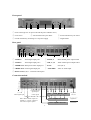
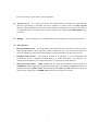
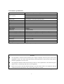
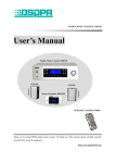
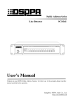
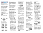
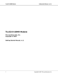
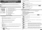
User's Manual
Welcome your patronage. Please read this manual carefully before use.
PA2089T
Programmable Timer
Performance features
l
LCD screen display, Chinese subtitle, with the operation status being clear at a glance.
l
Digital operation, graphic interface, multi-level menu operation mode, realizing practically the
most simple and easy operation.
l
The panel is provided with a direct selective key of force insertion type for the chime and the
power supply channel, available to intervene the program “manually” at any time.
l
The alarm trigger is available to enter the activating status at any time.
l
Programmable timer for a week, available to set up more than 60 time points everyday, and with
memory of the time and program when power is cut off.
l
4 power supply channels for programmable control timer.
l
The sharp hour chime presentation, three kinds of chime available for selection inside the system.
l
Available to control externally the equipment, such as “CD player”, “tuner”, “play deck” and
1
“player”, etc.
2
This page is for the summary record of consumer.
3
Front panel
①
③③
④③
②
⑤⑤
⑤⑤
⑥
① Power switch (press 1 for power ON and the power indicator is lit.)
② LCD screen
③ Forced insertion key for chime
④ Forced insertion key for cancel
⑤ Forced insertion key for change over of power supply
⑥ Digital wheel
Rear panel
① ④② ③
⑤
⑥
⑦
⑧
⑨
① ALM1 IN
Alarm signal input port 1
⑥ MAIN1, 2
Main channel power output socket
② ALM2 IN
Alarm signal input port 2
⑦ CH1, 2, 3, 4
Timer channel power output socket
③ TIMER OUT Main power alarm output port
⑧ F 20A
Fuse (20 A)
④ CHIME OUT Chime signal output port
⑨ ~220V/50Hz
220V AC mains input
⑤ DATA OUT1, 2, 3, 4 4-external control ports
Connection method
1
External control
signal output
2
Alarm signal input
CD
Chime signal
Main channel alarm output ON
available to connect equipment
such as time sequence power
TUNE DECK
REC
Pre-amplifier PA series
Power amplifier PA series
4
AC power
220V 20A
Signal line
Power line
Main interface
Power
1 ON
Friday
2 OFF
3 ON
4 OFF
13 : 38 : 26
Next timer point: 17:30 Friday
l
Power supply 1, 2, 3 and 4
The output operating status of rear panel CH1, 2, 3 and 4, with the
flashing for the forced insertion status;
l
Week: Hour: minute: second
The present specific week day and time (24 hours system);
l
Next timer point:
The specific week day and time (24 hours system) of the latest
programmable timer point;
l
!
The present valid alarm signal input of the rear panel ports ALM1 IN
or ALM2 IN;
l
The controlled peripheral equipment CD is playing at present;
l
The controlled peripheral equipment tuner is playing at present;
l
The controlled peripheral equipment player deck is playing at
present;
l
The controlled peripheral equipment digital recorder is playing at
present;
l
CHIME OUT port at the rear panel with chime signal output at
present.
Programming
l
Programming operation
display interface.
1.
Adjusting time
Operation entry interface has four entries: Timer programming, adjusting time,
duplicate timer and exit setup. Rotate the digital wheel to select the adjusting time entry, pressing
digital wheel again to enter the interface for adjusting time. Rotate the digital wheel to select the entry
to be adjusted, press the digital wheel to make the cursor of ▲▼ appeared behind the entry; Then
rotate the digital wheel to adjust the parameter, and press the digital wheel to exit from the adjusting.
Press the confirm entry after adjusting properly the other parameters following the method given above,
the adjustment made will take effect right away and the system will return back to the operation entry
interface; Press the cancel entry, all the adjustment will be invalid and the system will return back to
the operation entry interface. Press the exit setting entry of the operation entry interface to return
Press DIGITAL WHEEL to enter operation entry interface at the main
5
back to the main display interface.
2.
Timer programming
Press the digital wheel to select the timer programming entry to enter the
timer programming interface. There are 17 entries in the timer programming interface in sequence
as follows: Week □, ordinal number □, time □ : □, power supply 1 □ 2 □ 3 □ 4 □,
chime □, CD player □, tuner □, player deck □, digital recorder □, newly add, delete, delete
whole day and exit. Among them, the week entry parameter is used for locating the concrete date of
the program given; The ordinal number entry parameter is added for 1 automatically each time a newly
added entry is selected and pressed, and will be sequencing automatically in accordance with the
order of the time sequence of that very day. The entry parameter is only provided for use to check the
time point. It is required to press firstly the newly added entry to increase the blank time point to
provide for the writing when it is the first time to write the time point of that very day; The seven
entries such as the power supply channel (1, 2, 3 and 4) status, newly add, delete and exit are the
direct selective entries, and will take effect immediately when they are selected and pressed; As to the
delete the whole day entry, a confirm interface will be popped out if you press it, choosing and
pressing it further to take effect immediately; If that entry can not be chosen and pressed, then, there
must be no timer program on that day and all of all parameters inside the □ are all blank at this time;
The adjustable parameters for the other entries include: Press the entry to be adjusted with the digital
wheel so that the cursor of ▲▼ appears after the entry, go on rotating the digital wheel to adjust the
parameter, and press the digital wheel to exit from the adjustment (the adjustment will take effect right
away at this time.) Press the exit entry to return back to the operation entry interface after the various
parameters have been adjusted properly. Press the exit setting entry at the operation entry interface to
return back to the main display interface.
3.
Duplicate timer Press the duplicate timer entry with the digital wheel under the operating entry
interface to enter the duplicate timer interface. The interface contains nine comparably direct entries,
the operation of which may be fulfilled using the method of pressing. Press the cancel entry to return
back to the operation entry interface; Press the confirm entry to pop up an instruction interface for
the duplicate process, and it will return back to the operation entry interface automatically after
completing the process. Press the exit setting entry of the operation entry interface to return back to
the main display interface.
l
Clear the memory It is better to clear the memory thoroughly once prior to the programming to
prevent the residual program to be run unintentionally, resulting in confusion. There are two methods
of clearing the memory as follows:
1.
Adjust the parameter of the entry of week □ respectively under the timer programming interface as:
Monday, Tuesday, Wednesday, Thursday, Friday, Saturday and Sunday, pressing the delete whole day
entry respectively and confirming, and all the memories in the week will be cleared in 7 times.
2.
Press the delete whole day entry and confirm under the timer program interface, remember the
parameters of the present week day □ entry (for example: Monday). Then under the duplicate timer
interface, duplicate the whole day timer points of week day that you remember (for example: Monday)
to the other six days (for example: Tuesday, Wednesday, Thursday, Friday, Saturday and Sunday), and
6
all the memories in a week will be cleared completely.
l
Program browse It is necessary to browse the programs already compiled to prevent mistaking
after the programming is completed. The browse method is as follows: Enter the timer program
interface, adjust the week entry parameters and use them for locating the concrete date for browsing; It
is available to browse in real-time all the programs of that day by adjusting the ordinal number entry
parameter.
l
Running
l
Other functions
1.
Data protection function The programming will not effect the normal operation of other programs;
The programs compiled will run right away and have memory for power off; Including the memory for
the power off during the deleting and duplicating process and the memory for the time power off.
2.
Intelligent main interface The backlight indicator is lit manually, or is lit programmable and
automatically, and it is distinguished automatically in 1 minute when there is no operation; It is
distinguished automatically in 5 minutes when there is no operation for other interfaces.
3.
Main power logic output MAIN 1 and 2 will be turned on automatically and the interface of
TIMER OUT will be triggering the output alarm signal when any of CH 1, 2, 3 and 4 channels in the
program is turned on; MAIN 1 and 2 will be turned off when CH 1, 2, 3 and 4 channels are all turned
off; The alarm output signal of TIMER OUT interface will be stopped at this time.
The inner programs will be started and run after the equipment is normally powered on.
7
Performance specifications
Timer socket
Socket capacity
Timer points
Time system
Programmable channel number
Type of chime
Chime level
Alarm input
Alarm output
Alarm level
Controllable equipment type
Controllable equipment limit
Max. control distance
Protection
Power supply
Dimensions
Gross weight
Net weight
2+4 pcs (real time power net voltage)
MAIN 1:
220 V , 10 A
MAIN 2:
220 V , 5 A
CH 1, 2, 3 and 4: All are 220 V, 1 A
Programmable, no less than 420 time points
24 Hour system
4 (CH 1, 2, 3 and 4)
3
300mV
2 Channels
1 Channel
0 V (short-circuit)
Compatible for series CD player, tuner, player deck, digital recorder
4 sets (CD player, tuner, player deck, digital recorder each)
1 km
F20A AC fuse, 1 pc
AC 198-242 V/50-60 Hz
485×88×375 mm
11.3 kg
10 kg
No prior notice will be given if there is any change in the performance specifications.
Remarks
●
The equipment is not disconnected with the power supply completely when the power switch of the
equipment is under “off” status. Please pull out the power plug from the socket for the safety purpose
when the equipment is not to be used.
●
The equipment should not suffer from the drop of water or water splash and it is not allowed to place
objects such as vase filled up with water on the equipment.
●
Please do not open at will the machine housing to prevent electric shock. It is required to ask the
certified professional personnel to carry out the repair when it is needed.
DSPPA Acoustic Technology Co., Ltd.
.
8