1
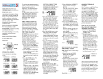
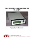
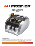
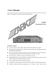
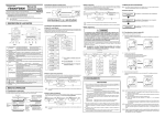
DTB Series User Manual
Thank you for purchasing our products, please read this manual before using and keep this manual
for future reference
In normal operation, the operator must not remove the controller from its housing or have
unrestricted access to the rear terminals, as this would provide potential contact with hazardous live
parts.
2.4 Setting value(SV) configuration
Setting value can only be configured when controller shows PV in the upper display and SV at the
lower display
When controller displays PV/SV
SET
Light press less than 1 seconds
Upper display shows the current PV, lower display flashes at its four digits with the last digits
brighter than other digits.
<R/S
to shift between different digits, when shift to target digits, press
increase and decrease the value
Installation and configuration must be undertaken only by technically-competent servicing personnel.
<
<
Digital Temperature Controller
to
Change the SV to 80 for example
1 Panel description
SV
SET
OUT1
OUT2
<R/S
ALM1
V
ALM2
V
Process value/Parameters display
Setting value/Value for various parameters
SET
:
<R/S
:
Function key, to goes to parameters list, to shift between parameters
to save and exit from parameters list
Shift to target digits/run or stop the program
V
V
:
Down key, decrease numerals
:
Up key, increase numerals
OUT1: Main output LED indicator
OUT2: Output 2 LED indicator
AT:
Auto-tuning process LED indicator
ALM1: Alarm 1 indicator
ALM2: Alarm 2 indicator
2 Base display mode and basic configuration
Light press less than 1 seconds
Exit to PV/SV status, SV setting finished
3 Field parameters and setting
Some crucial parameters can be configured within field parameters level listed as below:
Alarm value
PV Bias value
Auto-tuning switch on and off
Proportional band value setting(referred as P in PID control)
Integral time value setting(referred as I in PID control)
Derivative time value setting(referred as D in PID control)
Anti-reset windup value setting
Control cycle time setting
Protection Lock setting
can change
Below sequence for configuring the parameters within field parameters level, press
the value of parameters.
<
<
PV:
SV:
PV
AT
SET
When controller displays PV/SV
2.1 Power up self-check
This device will perform self-checking after power up, below is the display sequence for this process
SET
Upper display shows a symbol for input
Lower display shows the temperature unit and input sensor type
Press and hold still for at least five seconds to go to field parameters level
1
1 :[
2
2 :[
[ alarm value
SET
Upper display shows the default high limit for setting value
Lower display shows the default low limit for setting value
[ Auto-tuning switch, change the value to “1” will initialize the auto-tuning
process
SET
Upper display shows the current process value
Lower display shows the current setting value
” and flashes, indicates overscale, check the sensor wiring and
Upper display show “
input code
” and flashes, indicates underscale, check the sensor wiring and
3 :[
[ function disabled
4
4 :[
[
5
5 :[
[ controller’s auto-tuning process,but can also be modified manually by
SET
2.2 Error Display
Upper display show “
input code
3
Proportional band value for PID controller, the value for P normally
calculated by controller’s auto-tuning process,but can also be modified
manually by technically-competen personnel to have a better control result
SET
Upper display shows the PV value but flashes means all wiring are correct but the PV has
exceed the range of setting value high or low limit, adjust the setting value range.
2.3 Run and stop the program
Integral time value for PID controller, the value for I normally calculated by
technically-competen personnel to have a better control result
SET
6
6 :[
[
7
7 :[
[ Anti-reset windup parameters, call suppress the overshoot or undershoot
SET
Derivative time value for PID controller, the value for D normally
calculated by controller’s auto-tuning process,but can also be modified
manually by technically-competen personnel to have a better control result
<R/S
<R/S
Press shift key and hold still for more than three seconds can run/stop
the program
Page 1/3
8
8 :[
[ Control cycle time value
9
9 :[
[ To compensate the deviation of process value, the value can be negative or
SET
Change the lock value to “1000”
SET
10 10 : [
[ Lock value to protect controller away from unauthorized acess
Exit to PV/SV status
Press and hold still for at least five seconds will exit to PV/SV and save the
all changes has been made to the all parameters
Press simultaneously for more than 4 seconds
11 : [
Range
Alarm value
-1999 to 9999
50/50.0
1
auto-tuning switch
0 or 1
0
2
not applicable
not applicable
not applicable
3
Proportional band
0-9999 or 0.1~999.9
15/15.0
4
Integral time
1-3600 S
40
5
derivative time
1-3600 S
20
6
anti-reset windup
0~100%
25
7
cycle time
1-100S
20/2
8
PV Bias
-1999 to 1999/-199.9 to 999.9
0
9
Data Lock
See table 2
Factory default
Protection
11
Sequence
Meaning
SET
SET
13
SET
14
15
10
SET
Lock value
0000
SV and all parameters can be modified
0011
0001
Only SV and alarm value can be modified
0101
0010
All parameters expect alarm can be modified
0110
0100
All parameters expect SV can be modified
0111
16
Protection
Only SV can be modified
SET
Only alarm value can be modified
17
All parameters can be modified except SV and alarm
SET
All parameters are locked
18
4 System parameters setting(LEVEL 1)
Input sensor selection
Alarm mode selection
Output type code,output was fixed when products ready to ship, should not be modified.
Run/Stop function configuration
Follow below sequence to go to system parameters level 1
When controller displays PV/SV
SET
Press and hold still for at least five seconds to go to field parameters level
SET
Shift down along the list until the parameter “LCK” was located
0
0
0
1
1
1
1
0
0
0
1
1
0
0
0
0
1
1
1
0
1
0
0
1
1
0
1
1
0
1
0
1
0
1
1
0
1
1
1
1
1
1
1
1
1
1
1
1
0
0
1
1
1
1
0
1
0
1
0
1
14 : [
SET
Parameters can be configured within system parameter level 1 listed as below
0
1
0
Value
0
0
0
0
0
1
0
0
12
SET
0000
[ Input sensor type parameters, this controller support universal input
signals, to configure the controller and work with different signals,
please refer to table 3 for details,press
to change the
value of parameters
Table 3— Input sensor description
SET
Table 2— Protection lock details
Lock value
Press for more than three seconds until it goes back to PV/SV status
SET <R/S
Table 1--- Field parameter details
Legend
SET
<
<
SET
positive, for example -10 or +10, the actual display of PV=(measuring value
+ Pb value)
19
[
0
Input Type
K
J
L
E
N
R
S
B
W5Re/W26Re
PL II
T
U
Range
0
(0 to 1372 C)
(0 to 1200 0C)
(0 to 2320 0C)
(0 to 1390 0C)
(-199.9 to 400 0C)
(-199.9 to 600 0C)
Pt100(JIS/IEC)
JPt100(JIS)
(-199.9 to 649 0C)
(-199.9 to 649 0C)
0 to 5V DC
1 to 5V DC
0 to 20mA DC
4-20mA DC
-1999 to 9999
(configurable)
-1999 to 9999
(configurable)
0
(0 to 900 C)
0
(0 to 1000 C)
(0 to 1300 0C)
(0 to 1769 0C)
(0 to 1769 0C)
(0 to 1820 0C)
Alarm mode for #1 alarm
Refer to table 4 for details
Table 4— Alarm mode despcription
SET
0
Value
0
0
0
0
0
1
SET <R/S
0
0
0
0
0
1
1
1
SET
0
0
20
21
to exit
1
0
1
1
0
1
1
1
0
1
0
Alarm Type
Alarm disabled
Deviation high-limit alarm
Deviation high/low-limit alarm
Absolute value high-limit alarm
Deviation low-limit alarm
Deviation high-low limit reverse alarm
Absolute value low-limit alarm
Page 2/3
2
16 : [
[
Control mode selection. Code “0000” for direct/cooling control. Code “0001” for reverse/
heating control.
20 : [
[
Run/Stop function configuration, set value as “1001” will active the Run/Stop function via
panel by press <R/S ,set value as “1000” to disable the Run/Stop function
Parameters “SL2” “SL3” “SL5” “SL7” “SL8” “SL9” are not available for configuration
5 System parameters setting(LEVEL 2)
Some crucial parameters can be configured within in system parameters level 2 listed as below:
Setting range high/low limit when input is TC/RTD
Display range when input signal is analog signal(4-20ma/0-10ma/0-5V/1-5V)
Decimal point setting when input signal is analog signal
Action dead bank for on/off control mode
Hysteresis value for alarm
SET
SET
SET
Press and hold still for at least five seconds to go to field parameters level
SET
Shift down along the list until the parameter “LCK” was located
Change the lock value to “1000”
SET
SET
PV/SV
SET <R/S
27
28
29
30
31
27 28 29 30 is not available for configuration
6 Auto-tuning
Auto-tuning is a basic function of this controller, to have a better control result, the auto-tuning shall be
initialized from ambient temperature and shall only be initialized after the wiring was done properly on the
entire system.
The Setting value for auto-tuning process should be larger than the initial temperature where the
auto-tuning was triggered, and the minimum temperature difference should be 50C
PV( X 0C)
Follow below sequence to go to system parameters level 1
When controller displays PV/SV
SET
SV for auto-tuning> ( X 0C+50)
auto-tuning initialized
The auto-tune will stop automatically after three cycles of heating and natural cooling process. No action
should be made to the controller during the auto-tuning process.otherwise the auto-tuning will abort.
The controller will at on-off control mode during the auto-tuning process, grave overshoot is expected.
be sure to pay strict attention if the system is vulnerable to the overshoot. be sure to set proper SV
during auto-tuning in such a vulnerable system to avoid damage
7
Terminal Arrangement
Press for more than three seconds until it goes back to PV/SV status
8
Exit to PV/SV status
SET <R/S
90~260V ~
AC
9
Upper shows the “Cod” level code
Lower shows “0000”
11
G1 +
12
Upper limit display when input is analog(0-10mA/4-20mA/0-5V/1-5V)
SET
23 : [
G1 +
Lower limit display when input is analog(0-10mA/4-20mA/0-5V/1-5V)
Alarm/out2
SET
24 : [
G2 -
NC
G1
13
6
14
7
9
1
10
2
11
3
12 48mm*96mm
G1 +
Alarm/out2
4
26 : [
[ Hysteresis for alarm
0 to 100 or 0.0 to 100.0
0.0% to 10.0% of full scale for analog input(Factory default is 2.0)
G2 -
96mm*48mm
5
14
6
NO
15
16
5
11
6
11
9
1
10
2
11
3
NO
NC
12
4
96mm*96mm
13
NC
10
+ G1
A
RTD
B
TC
Voltage
Current
B
7
8
A
RTD
B
TC
Voltage
Current
B
G1 +
Out1
G2 -
DTB Series Instruction Manual
13
5
14
6
15
7
16
8
NO
NC
A
RTD
B
TC
Voltage
Current
B
_
SET
G2 -
4
NO
_
0 to 100 or 0.0 to 100.0
0.0% to 10.0% of full scale for analog input(Factory default is 2.0)
Out1
48mm*48mm 9
+
[ Hysteresis value for on/off control mode.
ALM2
NC
90~260V ~
AC
+
25 : [
A
OUT1 G2 +
RTD
B
TC
Voltage
Current
B
5
decimals(parameters not available when input is RTD/TC)
G1 +
26
4
NO
[ Decimal point setting when input is analog signal, maximum 3
SET
25
72mm*72mm
NC
90~260V ~
AC
[ Setting value low limit when input is TC/RTD
3
NO
[ Setting value high limit when input is TC/RTD
8
_
22 : [
2
- G2
_
G2 -
7
+
Out1
3
NO
G2 -
1
ALM1
10
Alarm/out2
SET
24
2
+
Change “Cod” value to “0001”
23
90~260V ~
AC
Press simultaneously for more than 4 seconds
G1 +
22
1
Page 3/3