1
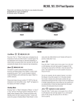
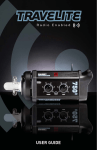
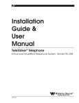
INTRODUCTION
Welcome to the Norman family of interchangeable high-quality flash equipment and thank
you for purchasing a Norman Monolight system. The utilization of larger high-duty-cycle
flash capacitors and related components enables this system to be utilized for demanding
commercial and portrait silver halide and digital applications that are not normally associated
with monolights.
FEATURES
o
o
o
o
o
o
o
o
400 watt-second capacity. The ML400 is an honest 400 watt-seconds (1000 w-s by
today’s advertising)
1/20-stop repeatability at full power. Holds this tolerance with line voltages from 105
to 125 volts.
150 watt quartz modeling lamp (250 watt max) with fan cooling.
Digital controls with LED display. Adjustable in 1/10-stop increments.
Error condition diagnostic readouts via internal software, as displayed in the LED
arrays (page 7).
Automatic thermal protection (page 7).
Interchangeable with over 100 Norman accessories and light modifiers with adapter
ring (part no. R9113).
Full two year limited warranty, including parts and labor.
Instruction
Manual
ML400 Monolight
2
IMPORTANT SAFEGUARDS
In accordance with UL122 specifications for photographic equipment.
When using your photographic equipment, basic safety precautions should always be
followed, including the following:
1. Read and understand all instructions.
2. Care must be taken as burns could occur from touching the flashtube or modeling
lamp.
3. Do not operate the appliance with a damaged cord or if the appliance has been dropped
or damaged, until it has been examined by a qualified service technician.
4. If an extension cord is necessary, a cord with a suitable rating should be used. Cords
rated for less amperage than the appliance may overheat. Care should be taken to
arrange the cord so it will not be tripped over or pulled.
5. When practical, unplug the appliance from the electric outlet when not in use. Never
yank the cord to pull it from the outlet. Grasp the plug and pull to disconnect.
6. To avoid electrical shock hazard, do not disassemble this appliance, but take it to a
qualified service technician when service or repair work is required. Incorrect
reassembly could cause an electric shock hazard when the appliance is subsequently
used.
7. CAUTION – Designed for indoor use only. Do not operate outside in the rain or in
inclement weather or in the presence of standing water.
8. The use of an accessory attachment not recommended by the manufacturer may cause
a risk of fire, electric shock, or injury to persons.
9. Always connect this appliance to a grounded outlet.
10.
Disconnect the unit from its source of supply before replacing the flashtube or
modeling lamp.
Warning: Changes or modifications to this unit not expressly approved by the party
responsible for compliance could void the user’s authority to operate the equipment.
Note: This equipment has been tested and found to comply with the limits for a Class A
digital device, pursuant to Part 15 of the FCC Rules. These limits are designed to provide
reasonable protection against harmful interference when the equipment is operated in a
commercial environment. This equipment generates, uses, and can radiate radio frequency
energy and, if not installed and used in accordance with the instructions, may cause harmful
interference to radio communications. Operation of this equipment in residential area is likely
to cause harmful interference in which case the user will be required to correct the interference
at their own expense.
UNPACKING AND QUICK START
Carefully unpack and remove all parts from the shipping carton(s). Do not discard or destroy
any packing materials until all parts of the equipment have been inspected, assembled, and
working properly.
Inspect all parts for damage due to shipping. If any damage is found, contact the delivery
carrier immediately. Claims should be made to the delivery carrier before destroying shipping
carton(s).
Place the ML400 unit on a stable light stand that will properly support the weight of the
ML400 and any accessories that will be attached. The ML400 stand adapter is designed to
accommodate light stand tops from 3/8” to 5/8” studs. Secure the ML400 unit to the light
stand with the threaded knob.
The Modeling Lamp and Flashtube are shipped uninstalled to avoid damage. To avoid
electrical shock, always unplug unit from AC power when installing or removing modeling
lamp or flashtube. Use a clean glove or cloth to handle flashtube and modeling lamp to avoid
transfer of body oils to domes (this can significantly diminish the life of the lamp). Carefully
install the modeling lamp into the socket, push and turn the lamp until it is seated properly.
Carefully install the flashtube making sure that it is seated fully into the sockets. This avoids
arcing that can cause premature failure of the sockets.
Install the reflector to the front of the unit. Place the top of the reflector under the top lip first
and then just press the bottom into place. (The reflector should snap into place.) To remove
the reflector simply squeeze the two arms at the bottom of the unit together and swing the
reflector away from the unit.
With the ML400 power switch off, plug the AC cord into the unit and then into a 3-prong
grounded receptacle. Turn the power switch on. When the ready light turns on the unit has
reached the power level displayed on the control panel.
Flash Rate
This unit is designed to quickly recharge to full power in about 1.9 seconds. However,
continuous rapid flashing of the unit, without resting, may overheat and damage the flashtube
and internal components. At maximum power, the recommended continuous cycle rate is 12
seconds between flashes. In addition, up to 4 minutes of rapid firing at a 4 second flash rate is
possible. By lowering the power and/or increasing the time between flashes you can extend
the duration of rapid flashing. Alternatively, the cycle rate may be increased by lowering the
power and/or decreasing the duration of rapid flashing.
Warning: Never operate this equipment with the flashtube cover installed. This will cause
damage to the unit due to overheating.
3
4
CONTROL PANEL / OUTLETS / BASIC OPERATION
5. SYNC Outlet
The camera connects to this outlet via the R4155 Sync Extension Cord (included). The socket
(female) end of the Sync Extension Cord connects to the camera sync cord (not included).
Most 35mm and 120mm cameras utilize a standard “PC” sync cord which is available through
your photo supply store.
Proper polarity is important with cameras that utilize grounded shutter switch circuits
(cameras that utilize PC cords). If the unit does not flash on initial set-up the polarity may be
reversed. To achieve the correct polarity – Reverse the camera sync cord at the point where it
joins the Sync Extension Cord. This establishes a common ground between the camera body
and the flash unit. If the polarity is incorrect the unit could self-flash or flash intermittently.
6. Photo Eye (Slave)
Permits remote triggering from other flash units. The Photo Eye is automatically disabled
when a ¼” sync plug is inserted in the SYNC outlet.
7. RESET 10 Amp Circuit Breaker
Automatically protects the flash circuit against excessive overloads. When activated, it will
pop out about ¼” and the unit will become inoperative. To reset, wait at least 30 seconds and
depress the RESET button. If the circuit breaker continues to activate, consult the factory or
your authorized Norman service center.
8. Flash Power +/- Pushbutton Switches and LED Display
Controls the unit output in 1/10-stop increments over a 5-stop range plus “full” (6-stops total).
Tap the + or – pushbutton switch for each 1/10-stop change. Hold the pushbutton switch
down and the change accelerates for convenience. Once the approximate power level is
obtained, tap the pushbutton switches until the desired setting is obtained.
The LED can display the output in two modes: f-stop reduction or watt-seconds power level.
Press both the + and – pushbuttons at the same time for at least 2 seconds to change display
modes.
1. AC Power Inlet
Connects to the AC power cable. The AC input is 115 volts, 60 Hz. The unit is voltage
stabilized to provide 1/20-stop full power repeatability with AC line voltage fluctuations of 20
volts (105-125 volts).
2. Power Switch
Switches the AC power on/off. A memory circuit retains the output settings when the unit is
switched back on or when the AC power is interrupted.
3. Modeling Lamp
Depress the pushbutton switch to toggle between the three modeling lamp modes:
FULL - The modeling lamp is at full brightness regardless of the flash power setting.
RATIO - The modeling lamp will automatically ratio (track) with the flash power
setting.
OFF - The modeling lamp is off (indicated by both the Full and Ratio LED’s off).
Error conditions are displayed on the LED, as outlined on page 7.
9. Ready Light
The unit is fully charged when the Ready Light is on. At minimum power (12.5 w-s) the
recharge time is approx. 0.32 seconds, and at maximum power (400 w-s) the recharge time is
approx. 1.9 seconds. The unit may be flashed before it reaches full charge.
10. Flash Verification
Flash verification will visually indicate when the unit has flashed. The modeling lamp will
cycle on and off, then return to its previous state.
This function can be enabled / disabled by toggling the Flash Verification pushbutton switch.
11. Computer Control Modular Jack
4. TEST Button
The unit can be flashed by depressing the TEST button. When changing power levels, power
can be discharged through the flashtube instantly with this button instead of waiting for the
power to be bled through the discharge resistor of the internal circuitry.
5
6
ADVANCED OPERATION
Alarm System
In the event of a misfire the LED display will blink bFL (see page 7). The alarm system is
reset automatically by flashing the unit or by pressing any button on the control panel.
Thermal Protection
The ML400 is protected with an internal overtemp cutout. In the event of an overtemp, the
modeling light will be disabled.
SERVICE
Should not be attempted by user. Consult an authorized Norman Service Center.
Modeling lamp or flashtube replacement. Always unplug unit and discharge stored energy
by pressing the Test button. Wait 10 minutes for any residual charge on the main capacitors to
bleed off and let the flashtube and modeling lamp cool before handling. Always handle
modeling lamp with clean gloves or cloth to avoid transfer of body oils to lamp dome.
Carefully remove old flashtube and/or modeling lamp and replace with new.
GENERAL TROUBLESHOOTING
Unit will not flash:
•
Flashtube is not installed properly. (see page 4)
•
Sync cord polarity not correct (see ‘SYNC Outlet’ page 6)
Unit does not turn on:
•
Check power cord
•
Check circuit breaker
Photo Eye does not flash unit:
•
Sync cord is plugged in (see page ‘Photo Eye’ page 6)
•
Trigger flash is out of range
Modeling light will not turn on.
•
Modeling lamp is not installed properly (see page 4)
•
Modeling lamp is broken
•
Modeling lamp is turned off. Check the control panel switches (see page 5)
Note: If you are still experiencing trouble after checking the above general troubleshooting
guideline contact Photo Control Customer Service.
Never place metal object or fingers into modeling lamp or flashtube sockets.
DIAGNOSTIC TROUBLESHOOTING / ERROR CODES
This information can assist the operator in determining the source of a malfunction and it can
assist an authorized Norman service center in servicing a Norman Monolight. These codes
flash on the LED Display, signifying the following:
General Errors
bFL – Indicates a misfire. Check if flashtube is installed, flashtube may need replacement.
hot – Indicates internal temperature has exceeded normal operating limits. Modeling lamp
will be disabled and automatically enabled when internal temperature returns to normal
operating range.
SPECIFICATIONS
Power:
Recycle Time:
Flash Duration:
Power Control:
Modeling Lamp:
Modeling Lamp Control:
Trigger:
Supply Voltage:
Consumption:
Voltage Stabilization:
Overload Protection:
Weight:
Flashtube:
Guide Number:
Sync Voltage:
400 W-S
1.9 sec.
1/1200 sec. (full)
Full to -5 F-Stops
150W (250W max)
Off, Ratio, Full
Built-in Photo-eye, ¼” Sync Jack, Test Button
105-125 VAC, 60Hz, 10A
10A
+/- 1%
10A Circuit Breaker
4.88 Lbs.
Quartz, full envelope
100 at 10 ft., ISO100, Bare Bulb
6 VDC
norman
Manufactured by Photo Control Corporation
www.photo-control.com
Email: [email protected]
4800 Quebec Avenue North, Minneapolis, MN 55428
(763) 537-3601 Voice, (763) 537-2852 Fax
(Pub. No. 335-032B)
7
8