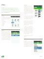
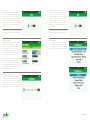
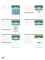
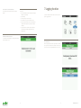
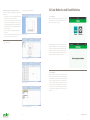
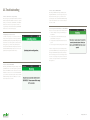
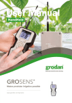
1
for the professional horticultural sector. Based on Precision Growing principles, these solutions are particularly applied to the cultivation of vegetables and flowers. In addition to its stone wool substrates, the GRODAN Group also provides tailor-made advice and tools to support Precision Growing and thus facilitate the sustainable production of healthy, safe and tasty fresh produce for consumers. More information on the GroSens System can be found at www.grodan.com/grosens Head Office GRODAN Group T +31 (0)475 35 30 20 Industrieweg 15 F +31 (0)475 35 37 16 www.linkedin.com/company/grodan 6045 JG Roermond [email protected] www.twitter.com/grodan P.O. Box 1160, 6040 KD Roermond www.grodan.com www.3xsustainable.com User Manual HandHeld GROSENS ® Makes precision irrigation possible www.grodan.com/grosens The Netherlands GRODAN is a registered trademark of ROCKWOOL INTERNATIONAL A/S. GroSens is a registered trademark of ROCKWOOL B.V. © ROCKWOOL B.V. GRODAN 2014 All rights reserved. All our information and advice is compiled with the greatest possible care and in accordance with state of the art technology. However we are unable to assume any liability for the contents. – October 2014 The GRODAN Group supplies innovative, sustainable stone wool substrate solutions 12 Table of contents 1Introduction 4 2 About the GroSens Reader 4 7 Logging function 19 7.1 Activate sensor 19 7.2 Main screen – start logging 20 2.1Specifications 4 7.3 Interval 20 2.2Components 4 7.4 Duration 20 7.5 Actual logging 20 3 Buttons 5 7.6 Check status of logging 20 7.7 Finalizing – stopping 20 4 Menus 6 7.8 Downloading – creating a file name 20 4.1 Home Menu 6 7.9 Important attention points 20 4.2 Device Menu 6 4.3 Sensor Summary 7 8 Stored files on reader 21 4.3.1 Sections 7 8.1 Reader data overview 21 4.3.2 8 8.2 Viewing multi-measurement files – summary on reader 22 Receiver Summary 8 8.3 Download files and detail display on a computer (in excel) 22 4.4 Row and Offset 4.4.1 Network Configuration 8 4.4.2 Row and Offset (Reserved for future use) 9 9 Downloader program – downloading files to PC 23 4.5 Preference Menu 9 9.1 Introduction – how to obtain the GroSens Downloader program 23 4.6 Slab Properties 10 9.2 Getting started – connect your reader and start de software program 23 4.7 Slab Type 10 9.3 Basic functions – Download and Erase functions 23 4.8 Slab Height 10 9.4 Sub menu’s - File menu 23 4.9 Slab Length 11 9.5 Sub menu – Edit 24 4.10 Select System 11 9.6 Sub menu – Actions 24 4.11 Set Time 11 9.7 Sub menu - Help 24 4.12 Set Date 12 9.8 Example of Excel files – multi measurement 25 4.13Language 12 9.9 Example of Excel files – logging measurement 26 13 4.14 Switch to 24 Hour Clock 4.15Brightness 13 10Low Batteries and Dead Batteries 27 10.1 Low Batteries 27 10.2 Dead Batteries 27 5 About 14 6 Multi measurements 15 11Troubleshooting 28 6.1 Create a File 15 11.1 Device won’t turn on or keeps resetting 28 6.2 Annotation – create name for the file 15 11.2 Updating Device screen is frozen 28 6.3 Blocks 15 11.3 Lost Connection with SENSOR 28 6.4 Readings 16 11.4 Lost Connection with RECEIVER 29 6.5 Test 16 11.5 Device’s System doesn’t match the one on the READER 29 6.6 Activate sensor 16 6.7 Start measurements 17 12Radio Frequency -declaration of Conformity 30 6.8 Add 17 12.1 European kitt: European and Russia 30 6.9 Store – break in multi measurement session 17 12.2 NA – kitt: North America and Australia systems 30 6.10 Reading – correct a reading 18 12.3 Row-lite kitt (Japan) 31 6.11 Discard – Delete all measurements 18 12.4 Row-kitt: New Zealand and other countries 32 6.12 End of measurement session 18 www.grodan.com 1 Introduction 3 Buttons Thank you for purchasing a GROSENS Handheld. This manual will help you understand the The READER has seven buttons that can be used to navigate through screens and functions of and get the most out of your Handheld. configure different settings. Below are some diagrams highlighting the buttons as their respective behaviors: The hand held has 3 main functionalities: 1. Read out measurements from a sensor 2. Multi measure function. This enables you to take several measurements in the greenhouse that will be reported back in averages and standard deviations. The recordings kan be easily downloaded to an excel file. 3. A logging function. Whit this function, you are able to record a number of measurements over a number of days. The recordings can be downloaded and displayed in an excel file (both measurements as well as a graph. Power The upper left button is the power button that will either turn the device on or off. After 10 minutes of inactivity, the device will automatically turn off to save power. If held down for more than 4 seconds and then released, the de- To export data to an excel file, a small software program needs to be downloaded and installed at a PC. This program vice will restart. called GroSens downloader can be found on our web page www.grodan.com/GroSens. In order to download files to your PC, the Handheld has to be connected to your computer via the supplied USB cable. If you have a full GroSens Multi measure system, the handheld can also be used to configure your GroSens system. Back The upper right button is the back button. When pressed 2 About the GroSens Reader it will return the device to the parent screen. Pressing back on a selection screen will cancel any changes that have been made on that screen. In the top menu (Home Menu) the back button has no effect. The READER is a hand-held readout device designed for use with all GROSENS system SENSORs and RECEIVERs made or sold for the GROSENS system. Directional Pad 2.1 Specifications Up, down, left and right buttons are located on the directiBattery Type 5 AA onal pad. Directional buttons are used to navigate through Battery Life 1500 mA hours lists and scroll wheels. Connector Type Wireless Connection 2.2 Components • GroSens Reader • GroSens SENSOR • Pin protector for the GroSens SENSOR Enter • 2 Radio Antenna The middle button on the directional pad is the enter but- • Mini USB Cable ton. Pressing the enter button when an item is highlighted • Manual will either go to a sub menu or save the highlighted setting to memory. On screens where a scroll wheel is visible, enter has no effect unless the DONE button is highlighted. 4 5 www.grodan.com 4 Menus 4.3 Sensor Summary The SENSOR summary screen shows all the pertinent information about the selected sensor. In the upper left The READER uses a variety of menus to perform basic tasks necessary. Every menu corner is the device’s name. When connected to a system, also displays a header that indicates the current GROSENS system (if present) you are the right side shows the radio signal strength from the connected to, the time of day, the signal strength from the READER to the nearest receiver SENSOR to the RECEIVER, otherwise it will show the signal strength of the SENSOR to the READER. Also on the right side is the battery level and percentage. The SENSOR bat- (if present), and the READER battery level. tery icon will change to red when it’s battery level reaches 20% capacity. 4.1 Home Menu Beneath the device’s name, is the currently configured Slab From the Home Menu, you can navigate to the 6 main me- Type. The slab type used is dependent on the slab proper- nus’. Use the left and right buttons to highlight the target ties setting. This will either be the READER slab properties menu in blue. Press the enter button to navigate to the or the section slab properties from the SmartBox. selected menu. 1. Devices set-up In the main portion of the screen on the right side you can 2. Multi measurement menu find a live update of the SENSOR’s volumetric water con- 3. Logging menu tent, temperature and electrical conductivity. These values 4. Stored files menu update typically ever two to three seconds and are depen- 5. Preferences dent on the Slab Configuration. 6. About menu On the right side you can find the SENSOR’s Section, Row and Offset configuration. When connected to a system, the location information can be configured and will update in the SmartBox’s web interface. Otherwise, the location infor4.2 Device Menu mation is left empty and cannot be configured. When avai- The devices menu is used to communicate with the lable, use the up and down arrows to select the different GROSENS SENSOR and RECEIVER (in case of a GroSens location settings. Press enter to edit the setting or press multimeasurement system is installed. SENSORs will not back to return to the Home Menu. connect to a READER until the TEST button on the SENSOR is pressed. RECEIVERs will auto populate in the list if they The detail Button is for Future purposes. This is not active are connected to the system shown in the upper right hand at current corner. Use the up and down arrows to select the item you would like to view and press the enter button to open up a screen with detailed information about that specific device. 4.3.1 Sections The Greenhouse section screen shows all the available sections that are configured for the GroSens system. Each section item shows both the greenhouse name as well as the slab type for that section. Use the up and down arrows to select the section you would like to use for this sensor and press the enter button to save the new setting. 6 7 www.grodan.com 4.3.2 Row and Offset 4.4.2 Row and Offset (Reserved for future use) The row and offset screens allow the configuration of each The row and offset screens allow configuring of each RE- SENSOR’s location so that you can keep track of the loca- CEIVER’s location so that you can keep track of the location tion of each sensor to make them easier to find after the of each RECEIVER to make them easier to find after the growing season is over. Use the up and down arrows to growing season is over. Use the up and down arrows to change each highlighted number. Press left and right to change each highlighted number. Press left and right to navigate between digits. Press back to cancel any changes navigate between digits. Press back to cancel any changes and press enter when DONE is highlighted to save your and press enter when DONE is highlighted to save your changes to the device. changes to the device. Note: This may be used in the future to help determine Note: This may be used in the future to help determine op- optimal distances between a SENSOR and a RECEIVER. timal distances between a SENSOR and a RECEIVER. 4.4 Receiver Summary 4.5 Preferences Menu The RECEIVER summary screen shows all the pertinent The preferences menu allows you to configure various uni- information about the selected receiver. In the upper left versal settings on the device. Use the up and down arrows corner is the device name. Beneath the name, is the sys- to select the target preference and press the enter button to tem that the receiver is currently paired with. edit the setting or press back to return to the Home Menu. In the main portion of the screen on the left side you can find the RECEIVER’s IP address, Gateway and Mask settings it’s using for the connected network. On the right side you can find the RECEIVER’S IP address type, Row and Offset configuration. When the IP address type is DHCP, the left hand side of the screen cannot be modified. When the IP address type is Static, you can use the left hand side of the screen to manually configure the RECEIVER’s system settings. 4.4.1 Network Configuration The IP address, mask and gateway for the target network can be configured in screens like the IP address screen above. Use the up and down arrows to change each highlighted number. Press left and right to navigate between digits. Press back to cancel any changes and press enter when DONE is highlighted to save your changes to the device. 8 9 www.grodan.com 4.6 Slab Properties 4.9 Slab Length Slab Properties allows you to specify the source of slab set- Slab length is used to indicate the length of the slab and is tings to use with a SENSOR. Each sensor can be tied to a important for SENSOR measurements. Use the up and down section and each section can have it’s own slab properties. arrows to select the target slab length and press the enter The slab properties can be set using the Reader or the button to save the setting or press the back button to return Smartbox. to the Preferences Menu without saving your changes. Note: Slab Properties must be set to “Use the READER slab configuration” for this configuration to take effect. 4.7 Slab Type 4.10 Select System You can use the reader to select a slabtype to be used for Select System allows you to view all the systems within Sensor measurements. You can select any of GRODAN’s range of the READER. Select the system that you would substrates, or select a specific fiber direction (X, Y, and Z). like to pair with. When viewing other devices, you will be Use the up and down arrows to select the target slab type prompted to pair any device that isn’t configured with the and press the enter button to save the setting or press the same system name. back button to return to the Preferences Menu without saving your changes. Note: Slab Properties must be set to “Use the READER slab configuration” for this configuration to take effect. 4.8 Slab Height 4.11 Set Time Slab height is used to indicate which height the GROSENS The time setting will synchronize with a connected SENSOR is placed. This is important for SENSOR measu- GRODAN GROSENS system. If no system is selected, then rements. Use the up and down arrows to select the target the time can be configured with this screen. Use the left slab height and press the enter button to save the setting and right arrows to select the target time component and or press the back button to return to the Preferences Menu use the up and down arrows to adjust the component set- without saving your changes. ting. To save the settings, navigate to the DONE button using the right arrow and press enter. Press the back but- Note: Slab Properties must be set to “Use the READER slab ton at any time to return to the Preferences Menu without configuration” for this configuration to take effect. saving your changes. 10 11 www.grodan.com 4.12 Set Date 4.14 Switch to 24 Hour Clock The date setting will synchronize with a connected GRO- This setting is used to toggle the time format in the screen DAN GROSENS system. If no system is selected, then the headers between 24 hour and 12 hour AM / PM formats. date can be configured with this screen. Use the left and Press the enter button when this option is highlighted to right arrows to select the target date component and use change the setting. the up and down arrows to adjust the component setting. To save the settings, navigate to the DONE button using the right arrow and press enter. Press the back button at any time to return to the Preferences Menu without saving your changes. 4.13 Language 4.15 Brightness The language menu will update all the text on the screens If you need to change the brightness of the display for to the selected language including the characters used. better viewing, you can do so by changing the brightness Use the up and down arrows to select a language and level. The higher the brightness the more battery power is press the enter button to save the setting or press the back required and consequently the less time a set of batteries button to return to the Preferences Menu without saving will last. Use the up and down arrows to adjust the bright- your changes. ness setting. To save the settings, navigate to the DONE button using the right arrow and press enter. Press the back button at any time to return to the Preferences Menu without saving your changes. 12 13 www.grodan.com 5 About 6 Multi measurements The About screen shows the device serial number, the firm- When the multi measurement function is selected (above), ware version and copyright notices. The firmware version you will enter in the multimeasurement setup (below) is also visible in the lower right hand corner of the splash screen. In the event that you need to contact customer support regarding your GROSENS READER, please be sure to inform the customer support specialist of your GROSENS READER’s serial number and firmware version 6.1 Create a File When selecting the multi measurement function (hitting enter), a file has to be created. In the multi measurement setup has to be defined. 6.2 Annotation – create name for the file Annotation (hit enter when it lights up un blue) will take you to the above shown screen. By using up and down arrows you can define the name for the file. When done, hit enter. 6.3 Blocks Define how many sections/different slab types you want to measure. Each slabtype or section should be 1 block. You can set the number by hitting enter if the Blocks appears blue, use the up and down arrows to set the number. Select done and hit enter when ready. 14 15 www.grodan.com 6.4 Test 6.7 Add Note: Hit start when ready. When a reading is ok, you should click the add button (it • After the sensor is inserted in a slab, it will take up to should be highlighted in blue and click enter). When hit- 10 seconds for the final reading appears. It is recom- ting enter, the add button will light up for about 3 seconds. mended to wait 10 seconds before hitting the Add After that the reading on the display will show 2/3. Below button) • If very low values on WC (<10%) or EC readings of 0,00 the measure value the average and standard deviation of appear, the sensor was exposed to air and readings are all readings until that moment are given. not representative for a slab measurement 6.8 Store – break in multi measurement session Stopping and restarting a measurement session Whit this function, all measurement that are taken are sto- • If one wants to break of a measurement session before all blocks or measurements are taken, you should hit the red. This button should be used if you want to stop with the store button to store data in the file. measurements. • If you want to continue the measurement you simply start up the multi measurement function again. The 6.5 Activate sensor screen will ask whether you want to resume the unfini- After the file is created, the reader will ask to push the sen- shed session or start a new file. When Resume is chosen, sor button. The number of the sensor the button is push the old session will continue. When a New is chosen, I appears in the screen and is highlighted. Push enter to new file can be created and a new session started. select. 6.9 Reading – correct a reading If you used the add button to quick and a false measurement was stored, this can be deleted by select the reading function. Make sure reading is blue and hit the enter button. A new screen will appear and ask you whether you really want to delete measurements. Click yes to proceed. In the next screen you have to select what reading what was good and enter that number. It will take you back to that number. All data after that number will be deleted. 6.6 Start measurements 1 The device is now ready to do measurements. On the left side the actual reading is given. On the right side information is given on what block and what reading you are. In the above given example you are about to conduct the first reading (1 out of 3) of the second block (2). 3 2 16 17 www.grodan.com 6.10 Discard – Delete all measurements An Example. Lets assume that measurement3 from 6 Selecting this function will delete all (stored) data of was wrong: that file. • The screen will indicate 4/6 > meaning that reading 4 will be the next reading • Select reading 7 Logging function Select the multifunction button in the main menu to start up the logging function • Confirm yes that you want to change • Select number 3 to go back to and select done • Your screen will now show 3/6 > the old 3 is deleted and the next measurement you are about to take is number 3. • If you role back more numbers (fe from 6 back to 2, all numbers after 2 will be deleted, in this case readings 3, 4,5. 6.11 End of measurement session Once all blocks and readings are completed, the data will be automatically stored. 7.1 Activate sensor After the logging function button is pushed, the reader will ask to push the sensor button. The number of the sensor appears in the screen and is highlighted. Push enter to select. 18 19 www.grodan.com 8 Stored files on reader 7.2 Main screen – start logging The main logging screen appears. In the top line the sensor number is shown that is activated. To start logging, select All files that are recorded, in multi measurements files or Log and hit enter. The log function now will show on. logging files and stored on the reader can be viewed in the Reader Data section 7.3 Interval 7.8 Downloading – creating a file name With the interval function, the time can be chosen after how To download the data from the sensor, hit the download many minutes a reading is taken. In the example above 3 mi- button. Now the annotation screens appears again and will nutes is chosen. Use the up and down buttons to select the give to add text or a name to the downloaded data file. The 8.1 Reader data overview appropriate interval. sensor number always will be given but text can be added When clicking on the reader data overview, a screen is afterwards. displayed that gives an overview of all on the reader stored files. 7.4 Duration After creating a filename, the actual downloading from the With this function you can set how many days the logging sensor will take place, the progress will be shown in the should take place. Lowest duration is 1 day but up to 14 days screen of the reader. In this screen 3 types of information is displayed: Type: indicating whether a file is a file that contains multi are possible. measurement data or logging data 7.9 Important attention points 7.5 Actual logging 1. The reader should be close to the sensor while down- With the logging on and interval and duration is set, the logging automatically will start. The actual logging of data takes loading the data. 2. For a larger amount of data (fe. 5 days of logging, every place on the sensor. Therefore it is not necessary to keep the reader on or close to the sensor. The screen can be closed Annotation: The name that has been given to a file. For logging files, the annotation also indicates the name of the sensor that supplied the logging data. 3 minutes) the download time can take up to 6 minutes. 3. Downloading will erase all data from the sensor and by hitting the back button and the reader can be taken back store it on the reader in a log file. to the office Records: The number of measurements that a file contains. Each record is a group of 3 measurements (WC, EC and Temp) and an id number and timestamp. By using the up and down arrow keys, one can browse 7.6 Check status of logging through the various files. The status of logging can be checked by selecting the log function, select the sensor by hitting the test button of the programmed sensor. The log screen will appear again and in the bottom of the screen the number of records logged will be displayed. 7.7 Finalizing – stopping The logging will automatically stop when the set duration is reached. If you want to stop the logging earlier, this can be done by pushing the download button. 20 21 www.grodan.com 9 Downloader program - downloading files to PC 8.2 Viewing multi-measurement files – summary on reader When a multi measurement file is highlighted, by clicking the enter button, a summary of the measured data is displayed: 9.1 Introduction – how to obtain the GroSens Downloader 1. The average and standard deviation on WC, EC and program. Temperature per measured block is given. In order to download measurement files to your Computer Please follow the instructions during the installation pro- the averages on each measured block. In the display you need to install a small program called GroSens Down- cess. The program will install an Icon for this program on behind block is indicated what block is presented loader on your PC. This program will automatically install your desktop. When clicking on this Icon the program will (1/4 – 2/4, etc). on your computer if you click on the link below (hold the start. Below you find a screenshot on what the program ctrl key and click on the link). looks like. 2. By using the up and down and enter key, one can view 3. Date and time are given when the measurements were recorded. 4. The number of measurements taken per block are indi- http://decagon.com/grosens/GrosensDownloaderInstaller-v1.0.151.exe cated behind reading/block 7.3 Download files and detail display on a computer (in excel). 9.2 Getting started – connect your reader and start de See chapter 8. software program When you connect the reader to your PC with the USB cable and start up the GroSens Downloader program, by pushing on download, data will be downloaded to your PC. Data will be stored as excel files and can be opened in Excel. To operate in this Software program, always have your reader connected to the PC! through the various files. 9.3 Basic functions – Download and Erase functions When you click on Download, all files stored on your reader will bedownloaded at once onto your computer in an excel format. After downloading, files will remain also available on the reader. By clicking Erase, all data stored on your reader will be deleted! 9.4 Sub menu’s - File menu When you click on the “file”menu , the main function are shown again (Erase and download). 22 23 www.grodan.com 9.5 Sub menu – Edit 9.8 Example of Excel files – multi measurement In this menu you can select in what form the files are down- The results of a multi measurement session will be presented loaded. Standard this is set in an excel format (.xlxs). It is also in 3 different sheets: possible to download data in a .csv format. In order to do 1. In the first sheet - multi measurement summary - the this, selct preferences and than bookmark the csv function. Some examples are presented below: averages of the measured blocks are given, as well as basic data on slabtype and when the measurements were done 9.6 Sub menu – Actions. 2. In sheet 2 – details - all individual measurements and In this menu you can: (again) the averages are presented. 3. In sheet 3 – main hardware information is found (serial Set reader date/time numbers of devices – softwareversions etc). Set the correct date and time on the reader Please note that all data in the excel file can be worked with Update sensor firmware Sheet 1 – Multimeasurement summary as in a normal excel file. install the latest firmware on your GroSens sensors. When clicking on this function – follow the instructions that appear on the screen – you can make sure that all your GroSens sensors have the latest firmware installed. The sensor have to be close to the reader in order to do this. Set Sensor mode with this function, the sensor can be set in system or kitt mode. Ask your Grodan specialist on how and when to use this function. Sheet 2 - details 9.7 Sub menu - Help There are 4 functions in this menu: 1. Sent feedback to Grodan: not active at the moment 2. Check for software updates: check if a newer version of the GroSens Downloader program is available. If available, the newest version will be installed on your PC – follow the instructions on your screen. 3. Check for firmware updates: this will check for the latest software on your reader. If a newer version is available, this will be installed on your reader. Follow instrucSheet 3 – hardware summary tions on the screen. 4. About GroSens Downloader: not active at the moment. 24 25 www.grodan.com 9.9 Example of Excel files – logging measurement Some examples are presented below: The results of a logging session will be presented in 4 dif- 10 Low Batteries and Dead Batteries ferent sheets: 10.1 Low Batteries 1. In the first sheet – Chart – all logged data on WC, EC and When the battery level reaches 20%, the battery icon in the temperature are presented in one graph. upper right corner of the screen will turn red. The device 2. In the second sheet - log summary - the min max values will continue to operate normally. logged on WC, EC and Temperature are given, as well as the individual graphs on WC, EC and Temperature. Furthermore basic data on slab type and when the measurements were done 3. In sheet 3 – details - all individual measurements are presented. 4. In sheet 4 – main hardware information is found (serial Sheet 1 - chart numbers of devices – software versions etc). Please note that all data in the excel file can be worked with as in a normal excel file. When the battery level is less than 5%, a warning screen is displayed asking the user to put in new batteries. The warning screen will remain visible until the batteries are changed or the device is turned off. All buttons are disabled except the Power button, which allows the device to be turned off before the batteries are removed. Sheet 2 – log summary 10.2 Dead Batteries When the batteries are dead, the device will turn off and remain off. All of the buttons are disabled, so pressing the power button will not turn it back on. The old batteries will have to be replace with new ones in order for the device Sheet 3 - details to function normally again. After new batteries are put in, the device will start up automatically. If the device hasn’t started up after 10 seconds, hold down the power button for more than 4 seconds and release it in order to restart the device. Sheet 4 – Hardware summary 26 27 www.grodan.com 11 Troubleshooting 11.4 Lost Connection with RECEIVER Most likely, the READER is having trouble talking to the target RECEIVER. Move closer to the target device, and 11.1 Device won’t turn on or keeps resetting then press back and try again. If you continue to have This issue is typically caused depleted batteries or batteries problems please make sure that the RECEIVER is running that have been put in backwards into the device. Open the at least version Firm ware version – contact Grodan custo- battery cover on the back of the READER. Confirm that the mer service for this. batteries are oriented correctly. If they are oriented correctly, then replace the batteries. Most likely the READER’s 11.5 Device’s System doesn’t match the one on the READER. batteries are too low to function properly. This screen can be caused by one of the following scenarios: 1. There are multiple GroSens systems within range of the READER 11.2 Updating Device screen is frozen 2. The target device is new and hasn’t been properly Sometimes it may take up to 10 seconds to save the new paired with the GroSens system. settings onto the target device. If it takes longer than this, 3. The target device was used with a different GroSens the READER is probably having trouble talking to the target system. device. Move closer to the target device, then press back 4. The GroSens system name was changed in the Smartbox. and try again. If you continue to have problems please make sure that the SENSOR is running at least version 1.12 and the RECEIVER is running at least version 1.10. You can In order to configure a device, it must be using the same update these through the SmartBox interface. system that the READER is using. Pairing the target device with system the READER is using should resolve this problem. If the wrong system is selected in the upper left corner of the screen, navigate to the preferences menu and select the correct system first before communicating with the target device. 11.3 Lost Connection with SENSOR Most likely, the READER is having trouble talking to the target SENSOR. Move closer to the target device, press back button on the READER to return to the device list. Press the TEST button on the sensor to reconnect with the READER. If you continue to have problems please make sure that the SENSOR is running at least version FW version – Contact Grodan Customer service for this. 28 29 www.grodan.com 12 Radio Frequency - declaration of Conformity Industry Canada Declaration of Conformity This device complies with Industry Canada licence-exempt RSS standard(s). Operation is subject to the following two conditions: (1) this device may not cause interference, and (2) this device must accept any interference, including interfe- 12.1 European kitt: European and Russia rence that may cause undesired operation of the device. The Grodan GroSens wireless sensing system uses license-free radio frequencies to communicate sensor data. These wireless devices constitute ‘short range device’ (SRD). Le présent appareil est conforme aux CNR d’Industrie Canada applicables aux appareils radio exempts de licence. L’exploitation est autorisée aux deux conditions suivantes: (1) l’appareil ne doit pas produire de brouillage, et (2) Applicable Material Numbers: GroSens Sensor 132253, GroSens Receiver 132256, l’utilisateur de l’appareil doit accepter tout brouillage radioélectrique subi, même si le brouillage est susceptible d’en GroSens Reader 132260, (EUR system) compromettre le fonctionnement Operating Frequency Range: Contains IC ID: 1846A-XB900HP 863-870 MHz (868 ISM band) Maximum Output Power: 25 mW (14 dBm) effective radiated power (e.r.p.) Interference Avoidance Technology: Listen Before Talk (LBT) + Automatic Frequency Agility (AFA) C-Tick Declaration of Conformity (for Australia) The devices comply with Radiocommunications (Short Range Devices) Standard 2004. EC Declaration of Conformity (for Europe and additional locales) These products are in conformity with the essential and relevant requirements of the EU Directive 1999/5/EC R&TTE and ACMA: N30375 the EU Directive 2011/65/EU RoHS2 Safety: (article 3.1a)EN60950-1:2006+A12:2011, EN 62311:2008 EMC: (article 3.1b) ETSI EN 301 489-1 V1.9.2 (2011-09) in accordance with ETSI EN 301 489-3 V1.4.1 (2002-08) Spectrum: (article 3.2) ETSI EN 300 220-2 V2.3.1 (2010-02) 12.3 Row-lite kitt (Japan) The Grodan GroSens wireless sensing system uses license-free radio frequencies to communicate sensor data. These wireless devices constitute ‘short range device’ (SRD). Applicable Material Numbers: GroSens Sensor 188180, GroSens Receiver 188179, GroSens Reader 188181, (RoW-Lite system) 12.2 NA – kitt: North America and Australia The Grodan GroSens wireless sensing system uses license-free radio frequencies to communicate sensor data. These wireless devices constitute ‘short range device’ (SRD). Applicable Material Numbers: GroSens Sensor 132254, GroSens Receiver 132258, Operating Frequency Range: 2410-2465 MHz (2.4GHz ISM band) Maximum Output Power: 10 mW (10 dBm) effective radiated power (e.r.p.) Interference Avoidance Technology: Direct Sequence of Multiple Channels GroSens Reader 132261, (CAN/USA/AUS system) EC Declaration of Conformity (for Europe and additional locales) Operating Frequency Range: 915.6-927.6 MHz (900 MHz ISM band) These products are in conformity with the essential and relevant requirements of the Directive 2004/108/EC (EMC), Maximum Output Power: 250 mW (24 dBm) effective radiated power (e.r.p.) Directive 2006/95/EC (LVD) and Council Directive 1999/5/EC R&TTE. Interference Avoidance Technology: Frequency Hopping Spread Spectrum (FHSS) Safety: (article 3.1a)EN60950-1:2006/A12:2011, EN 62311:2008 EC Declaration of Conformity (for USA) EMC: (article 3.1b) The devices comply with Part 15 of the FCC Rules. Operation is subject to the following two conditions: (i.) this device ETSI EN 301 489-17 V2.1.1 (2009-08) may not cause harmful interference and (ii.) this device must accept any interference received, including interference that Spectrum: (article 3.2) ETSI EN 301 489-1 V1.8.1 (2008-04) in accordance with ETSI EN 300 328 V1.7.1 (2006-10) may cause undesired operation. Contains FCC ID: MCQ-XB900HP FCC Declaration of Conformity (for USA) The devices comply with Part 15 of the FCC Rules. Operation is subject to the following two conditions: (i.) this device may not cause harmful interference and (ii.) this device must accept any interference received, including interference that may cause undesired operation. Contains FCC ID: OUR-XBEEPRO 30 31 www.grodan.com Industry Canada Declaration of Conformity The devices comply with all applicable requirements of the Industry Canada specifications RSS-210. Notes Contains IC ID: 4214A-XBEEPRO C-Tick Declaration of Conformity (for Australia and New Zealand) The devices comply with Radiocommunications (Short Range Devices) Standard 2004. ACMA: N136, Z1123 Japan Declaration of Conformity The listed products comply with the Technical Regulations Conformity Certification of Specified Radio equipment (ordinance of MPT N° 37,1981). ID:005NYCA0378 12.4 Row-kitt: New Zealand and other countries. The Grodan GroSens wireless sensing system uses license-free radio frequencies to communicate sensor data. These wireless devices constitute ‘short range device’ (SRD). Applicable Material Numbers: GroSens Sensor 132255, GroSens Receiver 132259, GroSens Reader 132262, (RoW system) Operating Frequency Range: 2410-2465 MHz (2.4GHz ISM band) Maximum Output Power: 63 mW (18 dBm) effective radiated power (e.r.p.) Interference Avoidance Technology: Direct Sequence of Multiple Channels FCC Declaration of Conformity (for USA) The devices comply with Part 15 of the FCC Rules. Operation is subject to the following two conditions: (i.) this device may not cause harmful interference and (ii.) this device must accept any interference received, including interference that may cause undesired operation. Contains FCC ID: OUR-XBEEPRO Industry Canada Declaration of Conformity The devices comply with all applicable requirements of the Industry Canada specifications RSS-210. Contains IC ID: 4214A-XBEEPRO C-Tick Declaration of Conformity (for Australia and New Zealand) The devices comply with Radiocommunications (Short Range Devices) Standard 2004. ACMA: N136, Z1123 32 33 www.grodan.com Notes 34 35 www.grodan.com