1
LASER IMAGER
DRYPRO MODEL 793
INSTALLATION MANUAL
CODE NO.
0792 (UL), 0791 (CE)
No. 26-2, Nishishinjuku 1-chome, Shinjuku-ku, Tokyo 163-0512, Japan
Table of Contents
Foreword.........................................................................................................1
Ch.1 Pre-installation Information .................................................................9
1.1
Installation Work Flow ......................................................................................10
1.2
External Device Connection Configuration.......................................................11
1.3
Installation Preparations ...................................................................................18
1.4
Part Names ......................................................................................................21
1.5
Structure ...........................................................................................................27
Ch.2 Unpacking and Installation ................................................................29
2.1
Packing List ......................................................................................................30
2.2
Unpacking ........................................................................................................32
2.3
Checking Accessories ......................................................................................35
2.4
Removing Protection Hardware and Installing Optional Units..........................36
2.4.1
Protection Hardware (Red) List ..........................................................................................36
2.4.2
Removing Protection Hardware Securing Back of Exposure Unit......................................37
2.4.3
Removing Protection Hardware Securing Front of Exposure Unit .....................................38
2.4.4
Removing Protective Film from Exposure Unit Conveyor Rollers ......................................39
2.4.5
Removing Protection Hardware Securing Pickup Unit (X 2 trays) .....................................40
2.4.6
Installing Supply Unit (Option) ............................................................................................43
2.4.7
Replacing the Removed Covers (1) ...................................................................................51
2.4.8
Removing Protective Sheet from Heat Processing Unit .....................................................55
2.4.9
Installing Heat Processing Unit ..........................................................................................60
2.4.10
Installing Deodorant Filter and Deodorant Filter Case .......................................................63
2.4.11
Installing Lis-793 (Option) ..................................................................................................65
2.4.12
Installing 1GB Print Memory (Option).................................................................................73
2.4.13
Replacing the Removed Covers (2) ...................................................................................75
2.5
Installing Accessories .......................................................................................76
2.5.1
Installing Exhaust Duct .......................................................................................................76
2.5.2
Installing Film Holder (Cable Protector) (Option) ...............................................................76
2.5.3
Changing Supply Tray Film Size Setting ............................................................................77
2.5.4
2.6
Installing UPS (Option) .......................................................................................................79
Starting Up .......................................................................................................81
2.6.1 Switching On Power ..................................................................................................................81
Ch.3 Setup ....................................................................................................83
3.1
Outline of DRYPRO 793 Setup ........................................................................83
3.2
Switching to the Service Maintenance Mode ...................................................86
3.3
Switching to the Normal Screen from the Service Maintenance Mode ............87
3.4
Film Setup ........................................................................................................88
3.5
SCP Setup........................................................................................................93
3.6
SCU Setup .......................................................................................................96
3.7
System Setup .................................................................................................102
3.8
User Registration............................................................................................105
3.9
Print Condition Setup .....................................................................................110
3.10
LUT Setup ......................................................................................................118
3.11
Time Set .........................................................................................................124
List of Time Zones .............................................................................................................................127
3.12
Maintenance Schedule ...................................................................................128
3.13
Sorter Setup ...................................................................................................131
Ch.4 Checking Image Quality ...................................................................135
4.1
Loading Film ...................................................................................................136
4.2
Calibrating Internal Densitometer ...................................................................140
4.3
Test Printing ...................................................................................................146
4.3.1
Printing Flat Pattern..........................................................................................................146
4.3.2
Printing SMPTE Pattern ...................................................................................................148
4.3.3
Flat Pattern Justification ...................................................................................................150
4.3.4
4.4
SMPTE Pattern Density Justification................................................................................150
Adjusting Image Data Write Start Position .....................................................154
Ch.5 Printing from and Backup of External Devices ..............................159
5.1
Printing from External Devices .......................................................................160
5.2
Backup ...........................................................................................................161
5.2.1
CF Memory Data Backup (CF -> HDD)............................................................................161
5.2.2
Setting Data Backup (DRYPRO 793 -> Maintenance PC) ...............................................162
Ch.6 Web Maintenance Mode ...................................................................165
6.1
Outline of Web Maintenance Mode ................................................................166
6.2
Starting Up and Terminating Web Maintenance Mode ..................................167
6.3
Web Maintenance Mode Menus.....................................................................170
Film Setup .....................................................................................................................170
SCP Setup ....................................................................................................................172
6.3.2
SCU Setup ....................................................................................................................173
6.3.3
6.3.4
Border Custom Setup ......................................................................................................176
System Setup...............................................................................................................177
6.3.4
User Registration ........................................................................................................179
6.3.5
Print Condition Setup .................................................................................................181
6.3.6
LUT Setup .....................................................................................................................186
6.3.7
Setting Current Time and Date ...............................................................................188
6.3.8
Maintenance Schedule Setup .................................................................................190
6.3.9
Sorter Setup .................................................................................................................191
6.3.10
6.3.1
Specifications.............................................................................................193
The following Medical Device approval applies:
Approval Number
Commercial Name
11BZ0539
La se r Ima g e r D RYPRO Vsta g e MOD EL 7 9 3
Foreword
This section sets out information with which the
service engineers must familiarize themselves before
proceeding with installation.
<1>
DRYPRO Vstage MODEL 793 Installation Manual Ver.1.00 2004.11
Foreword
Cautions Regarding Installation
The following cautions must be read before proceeding with installation and strictly observed.
1. To ensure safety, only qualified service engineers are permitted to open external covers or touch internal
components.
2. The device incorporates a laser unit (Class IIIb). Exposure of the eyes to the laser may result in serious injury.
Protective goggles must be worn at all while carrying out adjustments or repairs.
3. Under no circumstances should procedures or adjustments not detailed in this manual be attempted. Doing so
may result in harmful electromagnetic wave emissions.
4. Cautions indicated on warning levels must be observed at all times to ensure safety.
5. The device incorporates high-voltage components. Touching such components may result in electric shock:
care must be exercised.
6. Caution must be exercised to ensure that body parts or clothing do not become trapped in moving parts in the
device such as fans.
7. The weight of the device is approximately 255kg (285kg with sorter). Sufficient space to ensure safety must be
allowed during unpacking and installation.
8. Electrical circuitry in the device may be damaged by generation of static electricity. Care must be taken when
effecting repairs in handling both the main body and removed components.
9. Always ensure that the device power supply is switched off before disconnecting or connecting cables or
connectors. Under absolutely no circumstances should such procedures be attempted with the power supply on:
doing so may result in serious accidents.
10. Anti-static wrist bands must be worn at all times when handling circuit boards.
11. The device incorporates a lithium battery. Failure to follow correct procedure when replacing the battery may
result in damage: replacement should be carried out by a qualified service engineer.
12. DRYPRO 793 is a Class I laser device and is equipped with an interlock. The procedures detailed in this manual
must be followed when disengaging the interlock.
13.
Disposal of the DRYPRO 793 main body (lithium battery (including hexavalent chromium, cadmium, mercury,
PBB, PBDE), fluorescent tube (in liquid crystal module), accessories, options, consumables, packing materials
and film must be carried out in accordance with relevant local ordinances and regulations.
<2>
DRYPRO Vstage MODEL 793 Installation Manual Ver.1.00 2004.11
Foreword
Warning Text (Signal Word)
Signal words indicate the degree of potential hazards in the product.
There are 3 degrees of caution levels, and each is used depending on the level of risk and damage caused by
incorrect use and mishandling.
DANGER
: Failure to observe the caution will produce high risk of serious or fatal injury.
WARNING
: Failure to observe the caution will produce moderate risk of serious or fatal injury.
CAUTION
: Failure to observe the caution will produce risk of moderate or light injury.
or damage to property.
Risk of the damage
Bodily injury
(and damage to property)
High
Low
Loss of life or serious injury
(Damage is serious)
DANGER
WARNING
Moderate damage or light injury
(Damage is light)
WARNING or CAUTION
CAUTION
CAUTION
Damage to property only
<3>
DRYPRO Vstage MODEL 793 Installation Manual Ver.1.00 2004.11
Foreword
Warning Labels
Warning labels on the DRYPRO 793 are affixed at the locations shown below, and indicate possible danger
to the user.
p.7
Description of Warning Labels
Locations of
Warning
Labels
(1) Laser Caution Label
(2) High Temp. 100: Label-1
(3) High Temp. 100: Label-2
(5) Jam Release Label-A
<4>
DRYPRO Vstage MODEL 793 Installation Manual Ver.1.00 2004.11
(4) Class1 Laser Product Label
Foreword
(6) Jam Release Label-B•C
(7) Film Loading Label
(8) Deodorant Filter Change Label
<5>
DRYPRO Vstage MODEL 793 Installation Manual Ver.1.00 2004.11
Foreword
(9) Cleaning Roller Cleaning Label
(10) High Temp. 130: Label
(11) Label Indicating Danger of Toppling
<6>
DRYPRO Vstage MODEL 793 Installation Manual Ver.1.00 2004.11
Foreword
p.4
Locations of Warning Labels
Description
of Warning
Labels
Internal
(8) Deodorant Filter Change Label
(1) Laser caution Label
(5) Jam Release Label A
To avoid the risk of
burns or electrocution,
ensure that labels do
not become grimy.
(7) Film Loading Label
Labels that have
(6) Jam Release Label B-C
become illegible or have
peeled off should be
replaced.
Rear and Left Side
(1) Laser Caution Label
(4) Class 1 Laser Product Label
Deodorant Filter Case
(3) Deodorant Filter Housing High Temp. 100; Label
(2) High Temp. 100; Label
<7>
DRYPRO Vstage MODEL 793 Installation Manual Ver.1.00 2004.11
Foreword
p.4
HPRO Unit Cover
Description
of Warning
Labels
(10) High Temp. 130; Label
To avoid the risk of
burns or electrocution,
ensure that labels do
not become grimy.
(11) Label Indicating Danger of Toppling
Labels that have
become illegible or have
peeled off should be
Cleaning Rollers
replaced.
(9) Cleaning Roller Cleaning Label
<8>
DRYPRO Vstage MODEL 793 Installation Manual Ver.1.00 2004.11
Chap.
1
Pre-installation
Information
This chapter presents information to be read and
assimilated before proceeding with installation.
<9>
DRYPRO Vstage MODEL 793 Installation Manual Ver.1.00 2004.11
Ch.1 Pre-installation Information
1.1
Installation Work Flow
For maximum efficiency, the installation procedure should be carried out in the sequence detailed below.
Preparations
(Ch.1)
Preparations
- Checking installation conditions (p.00)
- Checking the network (p.00)
- Preparation of tools (p.00)
Unpacking (p.00)
Removing Potective Hardwares and installing options
2.4.2 Removing Potective Hardware Securing Back of Exposure Unit (p.00)
2.4.3 Removing Potective Hardware Securing Front of Exposure Unit (p.00)
2.4.4 Removing Protective Sheet from Exposure Unit Conveyor Rollers (p.00)
2.4.5 Removing Potective Hardware Securing Pickup Unit (X 2 trays) (p.00)
2.4.6 Installing Supply Unit (Option) (p.00)
2.4.7 Installing Cover (1) (p.00)
2.4.8 Removing Protective Sheet from Heat Processing Unit (p.00)
2.4.9 Installing Heat Processing Unit (p.00)
2.4.10 Installing Deodorant Filter and Deodorant Filter Case (p.00)
Installation
(Ch.2)
2.4.11 Installing Lis-793 (p.00)
2.4.12 Installing 1GB Print Memory (p.00)
2.4.13 Installing Cover (2) (p.00)
Installing Accessories
- Exhaust Duct (p.00)
- Film Holder (p.00)
- UPS (Option)
Start Up
Service Maintenance Mode Settings
(Operation Panel or WEB maintenance PC)
Settings
(Ch.3)
3.4
3.5
3.6
3.7
3.8
Film Settings (p.00)
SCP Settings (p.00)
SCU Settings (p.00)
System Settings (p.00)
User Registration (p.00)
3.9
3.10
3.11
3.12
3.13
Print Condition Settings (p.00)
LUT Settings (p.00)
Setting Current Time and Date (p.00)
Regular Inspection Settings (p.00)
Sorter Settings (p.00)
Loading film (p.00)
Checking Image
Quality
(Ch.4)
Calibration of Internal Densitometer (p.00)
Test Printing
- Flat Pattern Printing (p.00)
- SMPTE Pattern Printing (p.00)
Checking printing from external devices
(Network cable connections, clamp installation) (p.00)
Printing
from and Backup
of External
Devices
(Ch.5)
Backup
- CF Memory Data Backup (CF -> HDD) (p.00)
- Setting Data Backup (DRYPRO 793 -> Maintenance PC) (p.00)
< 10 >
DRYPRO Vstage MODEL 793 Installation Manual Ver.1.00 2004.11
Ch.1 Pre-installation Information
1.2
External Device Connection Configuration
This section details the configuration of external device connection to DRYPRO 793.
Normally, DRYPRO 793 has a maximum external device connection capacity of 16CH. (Basic specification)
In cases where capacity in excess of 16CH is required, or where multiple devices are to be connected under
the same settings, connection of up to 20CH is possible under certain conditions. (Expanded port
specification)
The connection configurations are shown below.
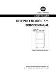
1.2.1 Basic Specification
In the basic specification, DRYPRO 793 has a maximum external device connection capacity of
16CH.
In cases where devices of other manufacturers are to be connected for direct DICOM input, a
DRYPRO multi-client license is required for the 2ch or more.
Example of 16ch in the Basic Specification
Total : 16 devices
CS-1
CS-1
CS-1
Printlink3
Printlink3
..............
CH1
CH2
CH3
............
CH15
DRYPRO 793
< 11 >
DRYPRO Vstage MODEL 793 Installation Manual Ver.1.00 2004.11
CH16
Ch.1 Pre-installation Information
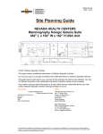
1.2.2 Expanded Port Specification
Conditions
The expanded port specification includes 5ch in addition to 15ch of the basic specification,
producing a total of 20ch.
The expanded channel configuration enables connection of a maximum of five additional
external devices to 1ch of the basic specification. The following conditions apply to the
external devices connected to the expanded port.
1. No. of Expanded ch
: 5ch
2. Devices that may be connected
: KDIS devices (RS Series, IS Series, Liteview)
REGIUS Series (backup settings only)
3. No. of sheets to be processed
: Devices with maximum daily print count of 20
sheets.
4. Setting Restrictions
: Unlike the basic specification, channel-specific LUT
settings or print condition settings cannot be made
for external devices connected to the expanded
5ch.
The LUT setting is fixed at linear and the print
condition settings are common to the expanded
5ch.
5. Preparations
: Before making expanded port settings, the Konica
Minolta sales department should be contacted for
details of system drawings.
Settings
In normal SCU settings, the "expanded port no." + "AE Title" setting is essential: with
DRYPRO 793, however, additional channels may be allocated to a 1ch expanded port without
AE title. (The port to which the additional channels are to be allocated is determined under
[SERVICE 1] - [SCP SETUP].
Use of the expanded port enables connection of a maximum of 20ch.
The expanded port and AE title of the external devices connected are set in the blank column.
< 12 >
DRYPRO Vstage MODEL 793 Installation Manual Ver.1.00 2004.11
Ch.1 Pre-installation Information
Example of 15ch Basic Specification + 5ch Expanded Port Specification
Total: 20 Devices
CS-1
CS-1
CS-1
Printlink3
LiteView
Liteview
Liteview
Liteview
Liteview
..........
CH1
CH2
...........
CH3
CH15
CH16
DRYPRO 793
Example of 15ch Basic Specification + 5ch Expanded Port Specification (2ch set as backup)
Total: 20 Devices
CS-1/CS-2
Printlink2
REGIUS IM
LiteView
Liteview
Liteview
CS-1/CS-2
CS-1/CS-2
............
CH1
CH2
CH3
CH4
...........
CH15
CH16
CH1
CH2
CH3
CH4
..........
Standard
Backup
DRYPRO 793
DRYPRO 793
< 13 >
DRYPRO Vstage MODEL 793 Installation Manual Ver.1.00 2004.11
CH15
CH16
Ch.1 Pre-installation Information
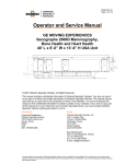
Flow Chart Showing Determination of Basic
Specification/Expanded Port Specification
A flow chart showing how to determine whether the connections should be made in the basic or
expanded port specification is set out below.
In cases where there is sufficient space and more than one DRYPRO 793 installed,
the basic specification should be selected.
Connection to
17 or more external
devices?
NO
YES
Connection to
20 or fewer external
devices?
NO
YES
2 or more
devices connected to
the expanded
port?
NO
YES
5 or fewer
devices connected to
the expanded
port?
NO
YES
3 or fewer
devices connected to
the expanded
port?
NO
YES
Connection in the
expanded port specification
should be made to 1 DRYPRO 793.
External devices should be
connected to 2 or more
DRYPRO 793 units.
Connections should be made
to 1 DRYPRO 793 unit is
the basic specification.
Adjustments should be made so
that three of the external devices are
not allocated to the expanded port.
Conditions for devices allocated to the expanded port.
- KDIS devices (RS Series, IS Series, Liteview) or REGIUS Series (backup settings
only)
- Maximum daily print count of 20 sheets per device.
- LUT setting fixed to "linear".
- Print conditions common to the additional 5ch.
< 14 >
DRYPRO Vstage MODEL 793 Installation Manual Ver.1.00 2004.11
Ch.1 Pre-installation Information
p.93 SCP SETUP
Illustrations of Examples of Basic/Expanded Port
p96
Specification Settings
SCU SETUP
Differences in settings between the connections in basic and expanded are detailed below.
Illustration of Example or Basic Configuration Settings
(Connection to 16 external devices in basic configuration.)
Total : 16 devices
CS-1
CS-1
CS-1
Printlink3
Printlink3
..............
CH1
CH2
CH3
............
CH15
CH16
DRYPRO 793
SCP SETUP
Expanded Port Channel Function
DRYPRO 793
CH
1
2
3
...
15
16
Connected
Device
CS-1
CS-1
CS-1
...
PrintLink3
PrintLink3
NO SELECT
Connection
Spec.
Use of Input Device
Basic
ON
Basic
ON
Basic
ON
...
...
Basic
ON
Basic
ON
SCU Setting
Input Device IP Address
192.168.20.90
192.168.20.91
192.168.20.92
...
192.168.20.104
192.168.20.105
< 15 >
DRYPRO Vstage MODEL 793 Installation Manual Ver.1.00 2004.11
Input Device AE Title
KC_CS1L_U001
KC_CS1L_U001
KC_CS1L_U001
...
KC_PRINK3_U001
KC_PRINK3_U002
Print Condition SETUP,
LUT SETUP
Individual Settings Possible
Individual Settings Possible
Individual Settings Possible
...
Individual Settings Possible
Individual Settings Possible
Ch.1 Pre-installation Information
Illustration of Example for Expanded Port Configuration Settings 1
(Connection to 20 external devices with CH4 set as the expanded port)
Total: 20 Devices
CS-1
CS-1
CS-1
Printlink3
LiteView
Liteview
Liteview
Liteview
Liteview
..........
CH1
CH2
CH3
...........
CH15
CH16
DRYPRO 793
DRYPRO 793
CH
1
2
3
...
15
16
Connected
Device
CS-1
CS-1
CS-1
...
PrintLink3
LiteView
LiteView
LiteView
LiteView
LiteView
SCP SETUP
Expanded Port Channel Function
CH 16
Connection
Spec.
Use of Input Device
Basic
ON
Basic
ON
Basic
ON
...
...
Basic
ON
Expanded
Expanded
Expanded
ON
Expanded
Expanded
SCU Setting
Input Device IP Address
192.168.20.90
192.168.20.91
192.168.20.92
...
192.168.20.104
Input Device AE Title
KC_CS1L_U001
KC_CS1L_U001
KC_CS1L_U001
...
KC_PRINK3_U001
(Blank)
(Blank)
< 16 >
DRYPRO Vstage MODEL 793 Installation Manual Ver.1.00 2004.11
Print Condition SETUP,
LUT SETUP
Individual Settings Possible
Individual Settings Possible
Individual Settings Possible
...
Individual Settings Possible
Common Settings
Ch.1 Pre-installation Information
Illustration of Example for Expanded Port Configuration Settings 2
(Connection to 20 external devices with CH2 set as the expanded port)
CS-1
Liteview
CH1
CH2
Liteview
CH3
Liteview
Printlink3
..............
Printlink3
CH16
DRYPRO 793
DRYPRO 793
CH
1
2
3
...
16
Connected
Device
CS-1
LiteView
LiteView
LiteView
PrintLink3
...
PrintLink3
SCP SETUP
Expanded Port Channel Function
CH 2
Connection
Spec.
Use of Input Device
Basic
ON
Expanded
Expanded
ON
Expanded
Basic
ON
...
...
Basic
ON
SCU Setting
Input Device IP Address
192.168.20.90
Input Device AE Title
KC_CS1L_U001
(Blank)
(Blank)
192.168.20.92
...
192.168.20.104
KC_PRINK3_U001
...
KC_PRINK3_U001
< 17 >
DRYPRO Vstage MODEL 793 Installation Manual Ver.1.00 2004.11
Print Condition SETUP,
LUT SETUP
Individual Settings Possible
Common Settings
Individual Settings Possible
...
Individual Settings Possible
Ch.1 Pre-installation Information
1.2.3 25µ Output
For a Regius-PCM system, the DRYPRO 793 super-fine mode (25µm) is required.
For connections to Regius contact mammography/normal photography and other modalities, the
normal mode (43.7µm) is used.
DRYPRO 793 requires the conditions shown below for 25µm output.
- 1GB expanded print memory.
- Loaded with mammography-dedicated film (film type <M>).
An example of output in the 25µm mode is shown below.
Connected to CS3 (Venus PCM Mode)
DRYPRO 793
SCU Setting
Size Type Check
ON
Tray-1 : 14x17 B
14x17 BLUE Dmax3.0
Tray-2 : 11x14 M
11x14 DR BLUE Dmax4.0
Tray-3 : 8x10 M
8x10 DR BLUE Dmax4.0
DRYPRO 793
CS-3
For 25um output, a command for output on the "DR BLUE FILM" film type must be
sent from CS-3.
For 25um output, giga-bit Ethernet is recommended to ensure a large image size.
< 18 >
DRYPRO Vstage MODEL 793 Installation Manual Ver.1.00 2004.11
Ch.1 Pre-installation Information
1.2.4 Mammo-film Output
In mammo-mode of other manufacturers, DRYPRO 793 high-density output (Dmax 4.0) is
required. For Regius normal photography and other modalities, Dmax 3.0 is used.
DRYPRO 793 requires the conditions shown below for Dmax 4.0 output.
- Loaded with mammography-dedicated film (film type <M>).
An example of mammo-film output is shown below.
Connection to Devices of other Manufacturers Using Printlink
The "BLUE FILM" output command from devices of other manufacturers must be converted to
"DR BLUE FILM" (Konica Minolta's unique standard) and sent to DRYPRO 793. For details of he
method of conversion and other relevant information, refer to the Printlink Manual.
SCU Setting
DRYPRO 793
Size Type Check
ON
Tray-1 : 14x17 B
14x17 BLUE Dmax3.0
14x17 BLUE Dmax3.0
Tray-2 : 11x14 M
11x14 DR BLUE Dmax4.0
11x14 BLUE Dmax4.0
Tray-3 : 8x10 M
8x10 DR BLUE Dmax4.0
8x10 BLUE Dmax4.0
Device of Other
Manufacturer
Printlink
DRYPRO 793
Connection with Devices of other Manufacturers without Printlink
To send a direct output command from the device that cannot change the Dmax, the following
settings must be made in DRYPRO 793.
[PRINT SETUP]
[PRINT CONDITION]
[Maximum density]
: "400"
[Maximum/minimum density value used] : "DICOM"
[Parameter priority setting]
DRYPRO 793
p.110 PRINT
CONDITION
SETUP
: DENSITY MAX set to ON.
SCU Setting
Size Type Check
OFF
Tray-1 : 14x17 B
14x17 BLUE Dmax3.0
Tray-2 : 11x14 M
11x14 BLUE Dmax4.0
Tray-3 : 8x10 M
8x10 BLUE Dmax4.0
DRYPRO 793
< 19 >
DRYPRO Vstage MODEL 793 Installation Manual Ver.1.00 2004.11
Device of Other
Manufacturer
Ch.1 Pre-installation Information
1.3
Installation Preparations
The following items should be checked before proceeding with installation.
1.3.1 1Checking Installation Conditions
Check to ensure that the place of installation meets the following requirements.
Checking the Place of Installation
- There must be no risk of exposure to water.
- There must no risk of exposure to the harmful effects of high pressure, extreme
temperatures, humidity, poor ventilation, direct sunlight, dust, salt, combustible
gases or sulphur.
- There must be no risk of tilting, exposure to vibration or shock (including transport).
- There must be no chemicals must be stored at the place of installation.
- There must be no risk of gaseous emissions.
- Ventilation must be sufficient to disperse any odours produces by DRYPRO 793.
- There must be sources of noise in the vicinity.
- There must be sufficient space to ensure that there will be no risk of tripping over or
pulling on power or ethernet cables.
- There must be sufficient space to ensure that air inlets and outlets at the side and
rear of the unit are not obstructed.
- The installation space must meet the dimensional requirements shown below.
Installation Space
100mm minimum
500mm minimum
500mm minimum
DRYPRO
793
Front of
Main Body
1000mm minimum
Maximum Space Requirements for DRYPRO 793
Normal
675mm
With ejection panel open (to resolve jams)
195mm
With left/right panels open (to resolve jams)
460mm
460mm
740mm
With upper and lower front covers open
(to replace deodorant filter or resolve jams)
With supply tray open (to load films)
When installing exhaust duct and clamp
26mm
54mm
62mm
62mm
630mm
580mm
< 20 >
DRYPRO Vstage MODEL 793 Installation Manual Ver.1.00 2004.11
Ch.1 Pre-installation Information
Checking Maintenance Space
Check to ensure that the place of installation allows for the maintenance space
dimensions shown below.
Maintenance Space
800mm minimum
1000mm minimum
DRYPRO
793
1000mm minimum
Front of
Main Body
1000mm minimum
Checking Power Supply Conditions
Check to ensure that a power outlet meeting the requirements below is available at
the place of installation.
- Voltage : AC120V (UL), AC220V-240V (CE)
- Frequency : 60Hz (UL), 50/60Hz (CE)
- Maximum current consumption: 9A(UL), 4.5A(CE)
- Ground : Type D
Checking the Place of Unpacking
Check to ensure that a space of 2.5m or more is allowed at the front (the side where
the locking screws are located) of the palette.
When unpacking DRYPRO 793, be sure to unload the unit from the front of the
palette.
Checking the Route of Transportation
Check to ensure that the route from the place of unpacking and the place of
installation meets the following requirements.
- Ensure that there are no steep gradients or steps that are likely to expose
DRYPRO 793 to shocks during transport.
- Ensure that entrances into and exits from any rooms through which DRYPRO 793
will be transported are of adequate dimensions to allow safe passage.
- Ensure that the floors on the rout of transportation are capable of supporting the
weight of DRYPRO 793 (approximate weight: 255kg (without sorter), 285kg (with
sorter) without warping or buckling.
Checking the Area where Power and Ethernet Cables will be Laid
The person responsible for laying cables must check the following items.
- The location of the hub to which DRYPRO 793 will be connected, the route along
which the Ethernet cable will be laid and the required cable length.
- The location of the power outlet (3P) to which DRYPRO 793 will be connected, the
route along which the power cable will be laid and the required cable length.
Check also to ensure that cables will be laid along< a21safe
route, not, for example,
>
crossing
DRYPRO Vstage
MODELcorridors.
793 Installation Manual Ver.1.00 2004.11
Ch.1 Pre-installation Information
1.3.2 Checking the Network
The following points should be checked with the facility network administrator in advance of
installation.
DRYPRO 793 (SCP) Related Settings
- IP addresses and sub-net masks (when DHCP server is not used) of DRYPRO
p.93 SCP SETUP
793, maintenance PC and gateways.
- DRYPRO 793 host name.
- DRYPRO 793 AE title and port number (print service).
Diagnostic Device Related Settings
- Number of diagnostic devices connected to DRYPRO 793.
- IP address of each diagnostic device.
- AE title of each diagnostic device.
- Port number of each diagnostic device (N-EVENT REPORT service).
- Print conditions used by each diagnostic device (format, film size).
1.3.3 Equipment and Tools Required for Installation
Before proceeding with installation, check to ensure that the following equipment and tools are
available.
Maintenance PC
- Model with 10BaseT/100BaseTX/1000BaseT network ports.
- PC with TCP/IP protocol installed.
- PC with Windows2000/XP OS.
- PC with Internet Explorer (version 5.5 or higher).
- PC with environment capable of executing Java script with the Web browser.
Equipment for Network Connection
- Hub (Used for direct connection to DRYPRO 793 and maintenance PC).
Hub with auto-negotiation capabilities as 100Base-TX hub recommended.
- Ethernet Cables
(For DRYPRO 793 -> Hub connection and maintenance PC -> Hub connection)
CAT5E or CAT6 should be used for 1000Base-T.
Tools
- Box Cutter
- Phillips screw driver
- Long phillips screw driver (90mm or longer) for disengaging the front cover lock.
- Flat head screw driver
- Radio pliers
- 13mm box wrench (with a long section below the neck). Alternatively, socket
wrench (with extension cover)
- Portable densitometer: X-Rite 331 (used to check image)
- Magnifying glass (used to check image)
< 22 >
DRYPRO Vstage MODEL 793 Installation Manual Ver.1.00 2004.11
p.96 SCU SETUP
Ch.1 Pre-installation Information
1.4
Part Names
DRYPRO 793 Part names required for installation are detailed below.
1.4.1 Front, Top and Left Sides
1) Front Upper Cover
4) Exit Cover
2) Supply Tray 1
5) Left Cover
3) Front Lower Cover
1) Front Upper Cover
When a film jam occurs I the HPRO
(heat processing unit)/cooling unit, open
this cover to remove the jammed film.
This cover is also opened to replace the
deodorant filter.
2) Supply Tray 1
(Standard: 1 tray, with option: 3 trays)
Film is loaded in these trays.
4) Exit Cover
When a film jam occurs in the ejection
unit, this cover may be opened to
remove the jammed film.
5) Left Cover
When a film jam occurs in the descent
transport unit, this cover may be opened
to remove the jammed film.
This cover may also be removed to
carry out cleaning of the cleaning roller.
3) Front Lower Cover
When a film jam occurs in the descent
or elevator transport units or the film
justification unit, this cover may be
opened to remove the jammed film. It is
also possible to access the film from
this opening and feed it through to the
left or right covers.
< 23 >
DRYPRO Vstage MODEL 793 Installation Manual Ver.1.00 2004.11
Ch.1 Pre-installation Information
1.4.2 Operation Panel
2) Operation Button
3) Operation Lamp
1) Operation Panel
4) Timer Lamp
1) Operation Panel
Operates and performs various setting for DRYPRO 793. Also displays various
messages.
2) Operation Button
Starts up or shuts down DRYPRO 793.
3) Operation Lamp
Operating
Start Timer ON
Shutdown Processing
Power OFF (breaker ON)
Power OFF (breaker OFF)
: Constant blue
: Constant blue
: Flashing blue
: Constant Orange
: Extinguished.
4) Timer Lamp (Green)
Illuminates when the start timer is ON.
< 24 >
DRYPRO Vstage MODEL 793 Installation Manual Ver.1.00 2004.11
Ch.1 Pre-installation Information
1.4.3 Rear and Right Sides
1) Film Exit Tray
7) Outlet
2) Front Upper Cover
Release Lever
3) Right Cover
8) Inlet
9) Ethernet Port
4) Power Breaker
10) Serial Port
5) Power Cable Connector
6) Power Cable
1) Film Exit Tray
Printed films are output to this tray.
When an optional 6ch sorter is installed,
films are output to the sorter.
2) Front Upper Cover Release Lever
Releases the front upper cover lock
when it is necessary to open the cover.
3) Right Cover
When a film jam occurs in the elevator
transport unit, this cover may be opened
to remove the jammed film.
4) Power Breaker
Turns ON/OFF main power.
5) Power Cable Connector
Connects the power cable.
6) Power Cable
Connects DRYPRO 793 to the facility
power outlet.
7) Outlet (4 locations)
Air used to cool the inside of the unit is
released from these ports.
8) Inlet(2 on the right side, 1 on the rear side)
Takes in air to cool the inside of the
unit.
9) Ethernet Port
Provides connection to the network.
10) Serial Port
The cable from the backup battery, if
used, is connected to this port.
Do not leave films equivalent to one package (= 125 sheets) or more on the Film Exit
Tray.
< 25 >
DRYPRO Vstage MODEL 793 Installation Manual Ver.1.00 2004.11
p.24 Ethernet Port
LEDs
Ch.1 Pre-installation Information
LEDs at the Ethernet Port
Two LEDs at the Ethernet port indicate the following.
Lower right of the rear side
Link / Activity LED
Com. Speed LED
- Link/Activity LED
Com. Status
LED
Link
Activity
Constant orange
Constant green
- Com. Speed LED
Com. Status
LED
10Mbps
100Mbps
Extinguished
Constant orange
1000Mbps
Constant green
< 26 >
DRYPRO Vstage MODEL 793 Installation Manual Ver.1.00 2004.11
Ch.1 Pre-installation Information
1.4.4 Options
1. Supply Trays 2, 3
1) Supply Trays 2, 3
1) Supply Trays 2, 3
Holds film.
2. Lis-793
1) Lis-793
2) Sorter Cover
1) Lis-793
Printed films are output to 5 bins in the
sorter and to to the film exit tray,
depending on the set-up.
2) Sorter Cover
When a film jam occurs in the sorter
transport unit, this cover may be opened
to remove the jammed film.
< 27 >
DRYPRO Vstage MODEL 793 Installation Manual Ver.1.00 2004.11
Ch.1 Pre-installation Information
1.4.5 Interior
1) Lever-A
7) Deodorant Filter Case
Housing (Yellow)
6) Deodorant Filter
2) Lever-B
4) Cover-B
5) Cover-C
3) Lever-C
Be careful not to touch
1) Lever-A (Green)
Locks the deodorant filter case.
2) Lever-B (Green)
Used when opening the left cover.
3) Lever-C (Green)
Used when opening the right cover.
4) Cover-B
When a film jam occurs between the
descent transport unit and the
justification unit, this cover may be
opened to feed the jammed film to the
descent transport unit.
5) Cover-C
When a film jam occurs between the
justification unit and the elevator
transport unit, this cover may be opened
to feed the jammed film to the elevator
transport unit.
6) Deodorant Filter
Removes odours generated during heat
processing. This filter must be changed
regularly.
the deodorant filter
housing (yellow) when
pulling out the
deodorant filter case.
The housing carries
temperatures in excess
of 100: and may
cause burns if touched.
7) Deodorant Filter Case
Contains the deodorant filter. To change
the deodorant filter, open the deodorant
filter case cover. When a film jam
occurs between the HPRO and the film
discharge units, the deodorant filter
case may also be removed to remove
the jammed film.
Levers and knobs in the
DRYPRO 793 are
painted in different
colors depending on
the purpose of use.
Blue : For
maintenance
and inspection
Green : For removal of
jam films.
< 28 >
DRYPRO Vstage MODEL 793 Installation Manual Ver.1.00 2004.11
Ch.1 Pre-installation Information
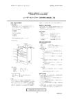
1.5
Structure
The internal structure of DRYPRO 793 is shown below.
Film is transported in sequence from (1) through (7) during the printing process.
11) Lis-793
10) Operation Panel
8) Deodorant Filter
6) HPRO Unit
7) Cooling/Discharge
Unit
1) Pickup Unit
5) Elevator Transport
Unit
2) Descent Transport
Unit
3) Justification Unit
4) Exposure Unit
Film Pass
9) Electrical Components Unit (rear)
1) Pickup Unit (incorporated in each tray)
Picks up films in the pickup unit one by one and feeds them to the descent transport
unit.
2) Descent Transport Unit
Feeds films picked up from the supply unit to the justification unit.
3) Justification Unit
Aligns the right and left edges of the film received from the descent transport unit
and feeds it to the exposure unit.
4) Exposure Unit (a: Sub-scan unit, b: Main scan unit)
Performs laser scanning in synchronization with film transport and prints an image
on the film.
5) Elevator Transport Unit
Feeds the film to the HPRO (heat processing) unit after exposure.
6) HPRO Unit
Heat-processes the exposed film.
7) Cooling/Discharge Unit
Cools and discharges heat-processed film.
8) Deodorant Filter
Removes odours generated during heat processing. The deodorant filter be
changed regularly.
9) Electrical Components Unit
Consists of the power pickup unit that supplies power to the device and the control
unit for that controls the entire device, communication with diagnostic devices and
image processing/control.
10) Operation Panel
Used to operate of and make settings for DRYPRO 793.
11)Lis-793 (Option)
Ejects the film discharged from the main body to the specified bin number.
< 29 >
DRYPRO Vstage MODEL 793 Installation Manual Ver.1.00 2004.11
Ch.1 Pre-installation Information
< 30 >
DRYPRO Vstage MODEL 793 Installation Manual Ver.1.00 2004.11
Chap.
2
Unpacking and
Installation
This chapter details procedures for unpacking and
installing DRYPRO 793.
< 31 >
DRYPRO Vstage MODEL 793 Installation Manual Ver.1.00 2004.11
Ch.2 Unpacking and Installation
2.1 Packing List
This list shows all components included in the DRYPRO 793 packing. A check should be carried out to
ensure that all components are present. If any components are missing, the package should be processed as
an incomplete consignment.
2.1.1 DRYPRO 793 Main Body
The components packed with DRYPRO 793 are shown below.
Lid
Shock absorber (Upper main body)
Ramp (Secured to the rear side of the main body)
(With clamp)
Deodorant filter
DRYPRO 793
Accessories Box (Secured the front of the min body)
Warranty, inspection certificate, operation manual,
documentation for medical staff, deodorant filter case,
2 suction pads, power cable, 1 cutters, 2 clamps,
exhaust duct, 2 film stoppers, accessory list, bag for
protective packing components (red), film size labels.
Shock absorber (Lower main body)
(One each at front, rear and left and right sides)
Pallet
Lever Board, Lever Platform
p.35 Checking
Accessories
< 32 >
DRYPRO Vstage MODEL 793 Installation Manual Ver.1.00 2004.11
Ch.2 Unpacking and Installation
2.1.2 Supply Tray (Option)
The components packed with supply tray are listed below.
Component Name
Tray Unit
Pick up Unit
Quantity
1
1
Accuride Rails
2
Cable (CH3 Signal Assy)
Cable (CH3 Power Assy)
1
1
Pick-up Unit Securing Component
(For right side of main body)
1
Pick-up Unit Securing Component
1
(For left side of main body)
Cutter
1
TP screws M4X8
Truss Screws M4X6
6
2
Front Cover Unit Assembly
1
Tray Cover Assembly
1
Remarks
Includes accuride rails
Pickup Unit ~ Mech Cntl Board
Pickup Unit ~ Power IF Board
Fixing screw
Screws for external covers.
2.1.3 Lis-793 (Option)
Use of the Lis-793 option enables discharged film to be allocated to six bins.
The components packed with the Lis-793 option (6ch sorter) are listed below.
Component Name
Quantity
Sorter main body
1
Sorter Separation Unit
Sorter Exterior Assy
1
2
Sorter Exterior
Blindfold Plate
2
1
Remarks
Sorter face cover, Sorter left cover
Sorter front and rear covers
Support
1
Used to secure bins
Retaining Plate
Stand
1
1
Bracket used to hold down bin from the top.
Bin
Roller Bush
5
2
Cable (Sorter Signal Assy)
1
Cable (Sorter Power Assy)
1
Connects the unit drive board to the
TP screws M4X8
13
power IF board.
Screws for attaching components
Sems 2 M3X6
Truss Screws M4x8
2
7
Used to attach wire to sorter cover.
Screws for external covers.
Support Bearing
Connects the unit drive board to the
mechanical control board
< 33 >
DRYPRO Vstage MODEL 793 Installation Manual Ver.1.00 2004.11
Ch.2 Unpacking and Installation
2.1.4 1GB Print Memory (Option)
This memory increases the DRYPRO 793 image processing speed. The 1GB print memory is
essential for 25µm output using the Regius-PCM system.
The components packed with the 1GB print memory are listed below.
Component Name
1GB Print Memory
Quantity
1
Remarks
2.1.5 Multi-client License (Option)
This a license allowing connection of devices of other manufacturers for direct DICOM input. One
license must be purchased for each device.
The components packed with the multi-client license are listed below.
Component Name
License Card
License Seal
Quantity
1
1
Remarks
To be handed to the user.
To be affixed to the DRYPRO 793
main body.
< 34 >
DRYPRO Vstage MODEL 793 Installation Manual Ver.1.00 2004.11
Ch.2 Unpacking and Installation
2.2 Unpacking
The procedure for unpacking DRYPRO 793 is detailed below.
The weight of the main body of DRYPRO 793 is approximately 255Kg (without
sorter)/285kg (with sorter). The weight of the unit with packing is approximately
313.5kg (without sorter). Care must be taken during transportation and sufficient
space must be allowed for ease of handling.
Unloading DRYPRO 793 from the palette must be carried out by two workers.
Additionally, a minimum space of 2.5m must be allowed at the front of the palette
(the side where the lock pieces are located) when unpacking the unit.
1
Disposal of the packing
materials should be
carried out in
accordance with
relevant local
ordinances and
regulations.
Cut the securing bands while holding down with
one hand.
Securing
Bands
Do not stand in front of
2 Remove the lid from the outer box.
the securing bands.
The bands are fastened
tightly and may hit any
Lid
personnel standing
nearby when cut.
3 Unscrew the knobs securing the lock pieces by
turning to the left and remove from the outer
box.
Using radio pliers to
turn the knobs will
3
Knob
facilitate removal.
4
Lock Piece
4 Remove the four lock pieces from the outer box.
5 Open and remove the outer box.
Outer Box
< 35 >
DRYPRO Vstage MODEL 793 Installation Manual Ver.1.00 2004.11
Ch.2 Unpacking and Installation
6 Cut the bands securing the ramp (attached to
the rear of the main body) and the accessories
boxes (attached to all sides of the main body)
and set the ramp in a place where it will not
obstruct unloading work.
Ramp
Accessories
Box
Shock
Absorber
7 Remove the box containing the deodorant filter
and the upper shock absorber.
Deodorant
Filter
8 Remove the packing bag covering the main
body.
Packing Bag
9 Remove the lever plate from the underside of
the DRYPRO 793 main body.
Lever Plate
< 36 >
DRYPRO Vstage MODEL 793 Installation Manual Ver.1.00 2004.11
Ch.2 Unpacking and Installation
10 Insert the removed lever plate frame from the
rear between the main body and the palette as
illustrated.
11 Raise the main body by turning the lever plate
screw using a socket wrench with ratchet and
remove the shock absorbers from the underside
of the main body.
3 ~ 5cm
DRYPRO 793
Lever Plate Screw
12 Likewise, raise the main body from the front and
remove the shock absorbers from the underside of
the main body.
Be careful not to allow
hands to become
trapped when removing
the shock absorbers
Be sure to remove the shock absorbers from the rear of the main body before
from the underside of
removing those at the front.
the main body.
This is because, while an anti-tilt plate is furnished on the side where the casters are
located at the rear of the main body, there is no anti-tilt plate at the front.
13 Set the ramp removed in step-6 at the front of
the palette.
Clamp
- The non-tapered side is the front.
14 Remove the clamp taped to the back of the
ramp and secure the palette and the ramp.
Ramp
15 Supporting the unit from left and right sides (one
worker at each side), slowly slide the DRYPRO
793 down the ramp and off the palette.
Be sure that no one is
standing in the path of
the DRYPRO 793.
If the unit should topple,
anyone standing in the
way may be injured.
Operation Panel Protective Sheet
16 Remove tape securing the supply trays and
covers.
Tape
17 Remove the protective sheet from the operation
panel.
< 37 >
DRYPRO Vstage MODEL 793 Installation Manual Ver.1.00 2004.11
Ch.2 Unpacking and Installation
2.3 Checking Accessories
The accessories listed below are provided with DRYPRO 793. Check to ensure that all accessories are
present. If any components are missing, the package should be processed as an incomplete consignment.
Component
Quantity
Remarks
Page
Warranty
1
To be handed to the user after installation.
-
Inspection Certificate
Operation Manual
1
1
To be handed to the user after installation.
To be handed to the user after installation.
-
Attached documents
1
To be handed to the user after installation.
-
Deodorant Filter
Deodorant Filter Case
1
1
To be installed during installation.
To be installed during installation.
00
00
Suction Cup
Power Cable
2
1
For film pick up by the pick up unit.
For power supply.
00
Cutter
2
Cuts and removes the film package when film is loaded.
00
Clamp
Exhaust Duct
2
1
Used to connect the network cable at the rear of the main body.
Used for exhaust direction control, noise reduction.
00
00
Film Holder
2
Used to prevent blockage of the outlet at the rear side.
(installation optional)
00
Accessory List
Bag for Protection Hardware
1
1
(red)
Film Size Label
Holds Protection hardware removed
00
during installation.
1
Shows the film size of film loaded in the tray.
To be affixed to the supply tray cover.
< 38 >
DRYPRO Vstage MODEL 793 Installation Manual Ver.1.00 2004.11
00
Ch.2 Unpacking and Installation
2.4 Removing Protection Hardware (Red) Parts and Installing Optional
Units
Protection hardware are set inside the device to prevent potential damage to internal components caused by
exposure to shock or vibration during transport.
Protection hardware must be removed in the sequence set out in this manual after transporting the device to
the place of installation.
2.4.1 Protection Hardware (Red) List
The protection hardware in DRYPRO 793 are listed below.
Since protection
hardware may be used
Page
Protection hardware
(Red) Type
Hardware securing rear of exposure unit (X1)
Protects the rear side of the exposure unit.
00
again, they must be
placed in the bag
Hardware securing front of exposure unit
Protects the front side of the exposure unit.
00
provided after removal
Protective film on exposure unit conveyor roller The exposure unit conveyor roller is protected by two films.
00
Hardware securing pick up unit (X2)
Protects each of the pick up units.
00
Protective sheet of heat processing drum
Protects the heat-processing drum.
00
and returned to the
manufacturer.
Operating DRYPRO
793 with protection
hardware still inside
may result in damage to
the unit.
Protection hardware securing
pick up unit (X1)
Protection hardware securing rear of exposure unit (X2)
Protection hardware securing front of exposure unit
< 39 >
DRYPRO Vstage MODEL 793 Installation Manual Ver.1.00 2004.11
Ch.2 Unpacking and Installation
2.4.2 Removing Protection Hardware Securing Back of Exposure
Unit
The procedure for removal of the components securing rear of exposure unit is described below.
1
Use fingers to remove the cap located at the
bottom of the right side of the main body.
Cap
2 Disengage the lower front cover lock by
inserting a driver with a shaft length of 90mm or
more shown below into the hole revealed at the
right side of the main body by removal of the
cap and pressing until a click is heard.
- This will disengage the lower front cover lock.
90mm or more
Lower Front Cover Latch
3 Open the lower front cover.
4 Remove the five screws (TP screws M4X8)
securing the exposure unit cover and remove
the cover.
Be careful not to make mistakes with the locations of removed screws.
Locations should be clearly marked for identification before screws are removed.
< 40 >
DRYPRO Vstage MODEL 793 Installation Manual Ver.1.00 2004.11
Ch.2 Unpacking and Installation
5 Remove the two screws (TP screws M4X8) at
the outer edges of the protection hardware
securing the rear of the exposure unit, leaving
the third securing screw in place, and
horizontally pull out the protection hardware.
Be sure to keep the
protection hardware
securing the rear of the
exposure unit horizontal
when pulling them out.
Failure to do so may
result in the tips of the
components impacting
- Proceed to removal of the protection hardware
securing the front of the exposure unit (2.4.3).
2.4.3 Removing Protection Hardware Securing Front of Exposure
Unit
The procedure for removal of the hardware securing the front of the exposure unit is described below.
1
Remove the five screws (TP screws M4X8)
securing the protection hardware at the front of
the exposure unit and remove the component.
- The exposure unit cover and lower front cover
should be left open for access during subsequent
procedures.
- Proceed to removal of the protective film on the
exposure unit conveyor rollers (2.4.4).
< 41 >
DRYPRO Vstage MODEL 793 Installation Manual Ver.1.00 2004.11
on internal components
causing damage.
Ch.2 Unpacking and Installation
2.4.4 Removing Protective Film from Exposure Unit Conveyor Rollers
After removal of the protection hardware at the front of the exposure unit, 2 protective films should
be removed from the exposure unit conveyor rollers.
1
Open the left cover by pressing lever-B (green).
2 Remove the tape securing the exposure unit
conveyor roller protective film to the DRYPRO
793 main body.
- The protective film is inserted between exposure
unit conveyor rollers.
3 Feed the sheet of exposure unit conveyor roller
protective film through to the left cover.
4 Remove the sheet of film collected at the
descent transport unit.
5 クリーニングローラーの固着による装置故障を
防止するため、レバーを2∼3回上下します。
・クリーニングローラーが回転します。
- The exposure left and front covers should be left
open for access during subsequent procedures.
- Proceed to removal of the protection hardware
securing the pick up units (2.4.5).
< 42 >
DRYPRO Vstage MODEL 793 Installation Manual Ver.1.00 2004.11
Ch.2 Unpacking and Installation
2.4.5 Removing Protection Hardware Securing Pickup Unit (X 1
trays)
After removal of the protective film from the exposure unit conveyor rollers, the protection
hardware securing the supply tray 1 pick units should be removed.
1
Disengage the upper front cover disengaging
lever and open the upper front cover.
Lift the lever to
disengage the lock.
2 Press lever C (green) and open the left cover.
3 Disengage the supply tray 1 lock by inserting a
driver with a shaft length of 90mm or more
shown below into the hole at the right side of the
main body and pressing down the latch.
- This will disengage the supply tray 1 lock.
4 Pull out supply tray 1 to its fullest extent.
< 43 >
DRYPRO Vstage MODEL 793 Installation Manual Ver.1.00 2004.11
Ch.2 Unpacking and Installation
5 Loosen the 2 screws (TP screws M4X8) and
remove the supply tray 1 cover.
Tray Cover
6 正面のネジ2本(TPネジM4x8)を外し、両端のネ
ジ各1本(TPネジM4x8)を緩めて, and remove the
supply tray 1 front cover.
7 Remove the screw (TP screw M4X8) securing
the protection hardware securing the pick up
unit and remove the component.
When removing the
Front side
- Removing the screw and pulling the protection
hardware forward a little will release the section
securing the rear of the pick up unit enabling
removal of the component.
protection hardware
securing the pick up
unit, be careful not to
cause damage with the
outer edges of the
component
Rear side
Protection hardware securing
the pick up unit
View of underside of pick up unit with
protection hardware in place
Since protection
hardware may be used
8 Return supply tray 1 to its position in the main
body.
- Removing the screw and pulling the protection
hardware forward a little will release the section
securing the rear of the pickup unit enabling
removal of the component.
- The procedure for installation of supply tray 2&3
(option) is described on the following page.
If supply tray 2 &3 is not to be installed, proceed to
installing covers (1) (2.4.7).
< 44 >
DRYPRO Vstage MODEL 793 Installation Manual Ver.1.00 2004.11
again, they must be
placed in the bag
provided after removal
and returned to the
manufacturer.
To set the protection
hardware back in place
in the event that the
unit is to be moved,
remove the pickup unit
before replacing the
protection hardware.
Ch.2 Unpacking and Installation
2.4.6 Installing Supply Tray (Option)
After removal of the protection hardware securing the pickup unit, the optional supply tray 2&3 may
be installed.
1
Check to ensure that all supply tray (option)
components are included in the consignment.
2 Disengage the supply tray 1 lock by inserting a
driver with a shaft length of 90mm or more
shown below into the hole at the right side of the
main body and pressing down the latch.
- This will disengage the supply tray 1 lock.
3 Pull out supply tray 1 to its fullest extent.
4 Loosen the two screws (TP screws M4X8) and
remove the supply tray 1 cover.
5 Set supply tray 1 in place in the main body.
< 45 >
DRYPRO Vstage MODEL 793 Installation Manual Ver.1.00 2004.11
Ch.2 Unpacking and Installation
6 正面のネジ2本(TPネジM4x8)を外し、両端のネ
ジ各1本(TPネジM4x8)を緩めて、 remove the
blindfold front cover from supply tray 2.
- The blindfold front cover is no longer needed.
Removed covers
should be kept for use
in the event that
unnecessary options
are removed in the
future. Disposal of any
7 Remove the Accuride rails from the pick up unit.
unnecessary covers
should be carried out in
accordance with local
ordinances and
regulations.
8 Secure the Accuride rails on the slide supports
on the inside of the main body.
(2)
(1)
Accuride rail hooks should be inserted into the square holes in the slide supports (2
holes each at the front and back of the main body).
9 Extend the Accuride rails until the screw holes
are visible.
10 Secure the Accuride rail with one screw (Truss
screw M4X6).
Apply downward pressure on the Accuride while screwing into place.
< 46 >
DRYPRO Vstage MODEL 793 Installation Manual Ver.1.00 2004.11
Ch.2 Unpacking and Installation
11 Secure the Accuride rail to the slide support at
the right side of the main body.
(2)
(1)
Accuride rail hooks should be inserted into the square holes in the slide supports (2
holes each at the front and back of the main body).
12 Extend the Accuride rails until the screw holes
are visible.
13 Secure the Accuride rail with one screw (Truss
screw M4X6).
Apply downward pressure on the Accuride while screwing into place.
< 47 >
DRYPRO Vstage MODEL 793 Installation Manual Ver.1.00 2004.11
Ch.2 Unpacking and Installation
14 Slide left and right Accuride rails into the main
body.
Sliding Accuride rails out to their fullest extent engages a lock rendering it
impossible to slide the rails back into the unit. The lock may be disengaged using a
finger (1) and then slid back into the unit (2).
(2)
(1)
Lock ON
Lock OFF
15 Remove the one screw (TP screw M4X8) and
remove the protection hardware securing the
pickup unit.
When holding the pickup unit, do not hold the guide plate that can be easily
deformed.Care should be taken so that the actuator of the passing sensor does not
fall off.
Actuator
Guide Plate
Set the pickup unit down with the side on which components are installed facing
up.
< 48 >
DRYPRO Vstage MODEL 793 Installation Manual Ver.1.00 2004.11
Ch.2 Unpacking and Installation
16 Holding the pickup unit by both sides, as
illustrated in the photograph, set the unit on the
two rails in the main body and set in place.
17 Remove one screw (TP screw M4x8) from the
position illustrates in the left.
18 Align the embosses to the receptacle holes (one
Screw hole for
securing togeher
with front cover.
on the main body, two on the pickup unit),
secure the hardware for fixing the left side of
main unit
Enbosses
The one remaining screw hole is used when installing the front cover.
19 Install the pickup unit and the component for
Screw hole for
securing together
with front cover.
securing the right side of the main body in the
position shown at left (pickup unit side) using
one screw (TP screw M4X8).
Embosses
The one remaining screw hole is used when installing the front cover.
< 49 >
DRYPRO Vstage MODEL 793 Installation Manual Ver.1.00 2004.11
Ch.2 Unpacking and Installation
20 Remove the 5 screws (Truss screws M4X8) and
remove the rear cover.
From this point on, the procedure involves handling circuit boards: a wristband must
be worn.
21 Secure the pickup unit to the rear side of the
main body using one screw (TP screw M4X8) at
the location shown at left.
22 Remove the 4 screws (TP screws M4X8) and
remove the mechanical control box cover.
< 50 >
DRYPRO Vstage MODEL 793 Installation Manual Ver.1.00 2004.11
Ch.2 Unpacking and Installation
23 Connect connector M15 of the accessory cable
MCN15
(CH Signal Assy) to MC15 on the mechanical
control board in the main body.
CN15
CH3 Signal Assy
24 Secure the cable (CH Signal Assy) to the
Mech Ctl Board
DRYPRO 793 main body at the location shown
at left (yellow square) using a clamp.
UJP5
UJJ5
25 Connect connector UJP15 of the cable (CH3
Signal Assy) to relay connector UJJ5 on supply
tray 3 visible through the window at the rear of
the tray.
26 Connect connector PCN12 of the accessory
cable (CH3 Signal Assy) to CN12 on the power
interface board located at the bottom of the rear
side of the main body.
27 Secure the cable (CH Signal Assy) to the
Window at rear of supply tray 3
UJP3
DRYPRO 793 main body at the location shown
at left (yellow square) using a clamp.
UJJ3
CH3 Power Assy
PCN12
CN12
Power IF Board
28 Connect connector UJP3 of the cable (CH3
Signal Assy) to relay connector UJJ3 on supply
tray 3.
29 Install supply tray 3.
- If supply tray is a 14-inch tray, change the film size
if necessary.
8インチ、または10インチのサプライユニットを取り付けた場合、, slide the tray
in and out a few times to ensure that Accuride rails are properly positioned and
secured. If the tray does not slide smoothly, reset the Accuride rails.
(12インチのサプライユニットを追加した場合、実施する必要はありません。)
< 51 >
DRYPRO Vstage MODEL 793 Installation Manual Ver.1.00 2004.11
Ch.2 Unpacking and Installation
30 Secure the supply tray 2 front cover using 2
screws the front (TP screws M3X6) and one
screw at each edge (TP screws M3X6).
31 Secure the supply tray 3 cover into position
using 2 screws (TP screws M4X8).
32 Slide supply tray 3 into position into the main
body.
If the supply tray configuration has been changed, the tray count setting under
"FILM SETUP"(TRAY SETUP) must be adjusted accordingly.
p.88 FILM SETUP
If the supply tray configuration has been changed, adjust and check the image write
p.154 Image Data
Write Position
Adjustment
start position.
< 52 >
DRYPRO Vstage MODEL 793 Installation Manual Ver.1.00 2004.11
Ch.2 Unpacking and Installation
2.4.7 Replacing the Removed covers
This section describes procedures for replacing covers removed during work procedures.
1
Disengage the upper front cover disengaging
lever and open the upper front cover.
2 Disengage the supply tray 1 lock by inserting a
driver with a shaft length of 90mm or more into
the hole at the right side of the main body and
pressing down the latch.
- This will disengage the supply tray 1 lock.
3 Pull out supply tray 1 to its fullest extent.
4 Loosen the two screws (TP screws M3X6) and
remove the supply tray 1 cover.
5 If necessary, change the supply tray 1 film size.
6 Remove the 2 top screws (TP screws M4X8)
and the two screws (TP screws M4X8) at the
edges (one at each edge) and remove the
supply tray 1 front cover.
< 53 >
DRYPRO Vstage MODEL 793 Installation Manual Ver.1.00 2004.11
p.77 Changing the
Supply Tray
Film Size
Ch.2 Unpacking and Installation
7 Slide supply tray 1 into place.
8 Disengage the supply tray 2 lock by inserting a
driver with a shaft length of 90mm or more into
the hole at the right side of the main body and
pressing down the latch.
- This will disengage the supply tray 2 lock.
9 Pull out supply tray 2 to its fullest extent.
Supply Tray Latch
10 Loosen the two screws (TP screws M3X6) and
remove the supply tray 1, 2 cover.
11 If necessary, change the supply tray 2 film size.
12 Remove the 2 top screws (TP screws M4X8)
and the two screws (TP screws M4X8) at the
edges (one at each edge) and remove the
supply tray 2 front cover.
< 54 >
DRYPRO Vstage MODEL 793 Installation Manual Ver.1.00 2004.11
p.77 Changing the
Supply Tray
Film Size
Ch.2 Unpacking and Installation
13 Slide supply 2 into place.
14 Close the right cover.
15 Close the left cover.
16 Secure the exposure unit cover into place using 5
screws (TP screws M4X8).
17 Close the lower front cover.
< 55 >
DRYPRO Vstage MODEL 793 Installation Manual Ver.1.00 2004.11
Ch.2 Unpacking and Installation
18 Affix film size labels to the level positions on
each of the supply trays.
Example illustrating:
Supply tray 1: 14X17. blue
- Proceed to removal of protective sheets from the
heat processing drum (2.4.8).
Leave the front cover open for subsequent
procedures.
Supply tray 2: 11X14, blue
Supply tray 3: 8X10: blue
< 56 >
DRYPRO Vstage MODEL 793 Installation Manual Ver.1.00 2004.11
Ch.2 Unpacking and Installation
2.4.8 Removing Protective Sheet from HPRO Unit
The procedure for removal of the 14X14 film and the mylar mat used to protect the HPRO (Heat
Processing Unit) drum from vibration or shock is detailed below.
1
Loosen 1 screw (Sems 2M3X14) and remove
the connector cover from the inside of the main
body.
The screw need only be loosened to remove the connector cover.
Removing the screws entirely produces the risk of the screws being dropped inside
the main body and makes the process of replacing the cover difficult.
2 Disconnect HPRO drum connectors from 3
locations (CN-A, CN-B, CN3).
CN3
CN-B
CN-A
3 Remove the 3 screws (TP screws M4X8)
securing the HPRO unit slide out plate to the
main body.
Be careful not to make mistakes with the locations of removed screws.
Locations should be clearly marked for identification before screws are removed.
4 Lifting up the 3 HPRO drum cables
disconnected in step-2, pull out the HPRO
slide out plate from the main body to its fullest
extent.
Make sure that the 3 disconnected cables do not come into contact with
components in the main body such as rollers: such contact may result in damage.
< 57 >
DRYPRO Vstage MODEL 793 Installation Manual Ver.1.00 2004.11
Ch.2 Unpacking and Installation
5 Remove the 2 cables on the far side of the
HPRO unit from their clamps.
6 Loosen the 4 screws (Sems 2 M4X8) at the
front and rear of the upper cover (HPRO unit).
The screws securing
the HPRO unit cover
Upper Cover
are designed so that
they cannot be removed
even when loosened.
Front
7 As shown at left, remove the upper cover
holding the left and right sides.
8 Set the removed upper cover top side down in a
safe place.
Because the heat roller
removed in step-15 will
be rested on the
removed upper cover,
make sure that the
cover is placed in a
safe location where
there is no risk of it
9 Remove the 2 screws (TP screws M4X8)
securing the upper opposing rack (one at the
front, one at the back).
< 58 >
DRYPRO Vstage MODEL 793 Installation Manual Ver.1.00 2004.11
falling or being
accidentally bumped.
Ch.2 Unpacking and Installation
(1)
(2)
10 As shown at left, tilt the upper opposing rack 90˚
with its outer edge as fulcrum before removing.
Tilt the upper opposing
rack 90˚ with the
fulcrum here.
11 Check to ensure that bearings or springs are not
damaged or loose.
- Any loose springs should be reset in position.
- In the event that springs are damaged or cannot be
reset into position, the product should be
processed as an incomplete consignment.
Disengagement or change of the upper facing rack bearing or spring may lead to
artifacts in image. Therefore, due care should be taken.
12 Remove the protective mylar sheet from the
heat-processing drum.
Care must be taken not to damage the HPRO drum.
13 Remove the heat-processing drum holding the
cable at the rear of the drum in the left hand.
< 59 >
DRYPRO Vstage MODEL 793 Installation Manual Ver.1.00 2004.11
Ch.2 Unpacking and Installation
14 Set the heat-processing drum down on the
upper opposing rack removed in step-8.
Care must be taken not to touch or damage
the surface of the heat-processing drum.
Additionally, do not leave the drum
unattended. Any damage to the drum will
have adverse affects on output images.
17 Carry out a visual check to ensure that the lower
opposing rack drum bearings or opposing roller
bearings are not damaged.
- If damage is detected, follow procedures detailed in
the "Service Manual".
18 Carry out a visual check to ensure that there is
no slack in the non-woven cleaning cloth.
Lower
Opposing Rack
Drum Bearings
- If any slack is detected, the cleaner unit should be
removed and any slack take up. (See the "Service
Manual").
Non-woven Cleaning Cloth
Opposing Roller Bearings
< 60 >
DRYPRO Vstage MODEL 793 Installation Manual Ver.1.00 2004.11
Ch.2 Unpacking and Installation
2.4.9 Installing HPRO Unit
After removing the heat-processing drum and checking for damage to any of the parts, the drum must
be re-installed without delay.
1
Holding the cable at the back of the heatprocessing drum in the left hand, place the drum
on the lower opposing rack.
2 Insert the protective film removed in "2.4.8
Removing Protective Sheet from HPRO Unit"
into the upper opposing rack as shown in the
left.
3 分離爪を手で浮かせて(1)、「2.4.4 露光部搬送ロ
分離爪
ーラー保護フィルムの取り外し」で取りだした
フィルムを、上対向ラックの下の平らな場所に
突き当たる位置まで差し込みます(2)。
(1)
(2)
ラック支持棒
4 余ったフィルムをラック支持棒に交互に潜らせ
て固定します。
< 61 >
DRYPRO Vstage MODEL 793 Installation Manual Ver.1.00 2004.11
Be careful not to
damage the heatprocessing drum.
Ch.2 Unpacking and Installation
5 Set the upper opposing rack with the film
inseted in the step-2 on the lever opposing rack,
and tilt the upper opposing rack 90˚ with the
fulcrum illustrated in the left.
Tilt the upper
opposing rack 90˚
with the fulcrum here.
6 Remove the film from upper opposing rack.
7 Secure the upper opposing rack with 2 screws
(TP screws M4X8), one at the front, the other at
the back.
8 Replace the upper cover holding the unit from
the front and back as shown at left.
Be careful of the orientation of the upper
cover to the heat-processing drum bearings
when replacing.
Replacement will be impossible unless the
Heat-processing drum bearings
heat-processing drum spindle does not
mesh with the spindle bearings.
Heat-processing drum spindle
< 62 >
DRYPRO Vstage MODEL 793 Installation Manual Ver.1.00 2004.11
Ch.2 Unpacking and Installation
9 Tighten the 4 screws (Sems2 M4X8) at the
front and back of the upper cover (heatprocessing unit).
Upper Cover
Front
10 Attach the cable at the far side of the heatprocessing unit the 2 clamps.
11 Holding the 3 heat-processing drum cables in
the left hand, return the heat exposure unit slide
plate into the main body.
Make sure that the 3 cables do no come into contact with internal components such
as rollers: such contact may cause damage.
12 Secure the heat-processing unit slide plate to
the main body using 3 screws (TP screws
M4X)8.
< 63 >
DRYPRO Vstage MODEL 793 Installation Manual Ver.1.00 2004.11
Ch.2 Unpacking and Installation
13
Reconnect the HPRO drum connectors at
three locations (CN-A, CN-B, CN3).
CN3
CN-B
CN-A
12 Tighten 1 screw (Sems 2 M3X14) to secure the
connector cover.
Ensure that the connector cover meshes with the lug at the back of the main body
interior.
Care must also be taken to ensure that cables do not become trapped by the
connector cover.
Lugs
< 64 >
DRYPRO Vstage MODEL 793 Installation Manual Ver.1.00 2004.11
Ch.2 Unpacking and Installation
2.4.10 Installing Deodorant Filter and Deodorant Filter Case
The procedure for installing the deodorant filter and case packed with DRYPRO 793 is described
below.
1
Remove the deodorant filter and case from the
packing box.
- The deodorant filter is packed in bubble packing
and a vinyl bag.
- The deodorant filter case is packed in bubble
packing.
2 Turn lever-A to the left and lift.
3 Install the deodorant filter case.
4 Slide the deodorant filter case lid (green) to the
left.
5 Open the deodorant filter case lid.
< 65 >
DRYPRO Vstage MODEL 793 Installation Manual Ver.1.00 2004.11
Ch.2 Unpacking and Installation
6 Set the deodorant filer in the filter case.
- As shown at left, the filter should be inserted with
the handle at the front and the holes in the
cardboard at the top.
7 Close the deodorant filter case lid.
8 Slide the deodorant filter case lid to the right (1).
- The deodorant filter case lid will lock into position.
9 Turn lever-A to the right (2).
- This will lock the deodorant filter case into position
in DRYPRO 793.
10 Close the front cover.
- Close the front cover firmly until it locks into
position.
- This concludes the procedure for installation of the
deodorant filer.
- Proceed to installation of Lis-793 (2.4.11).
If Lis-793 is not to be installed, proceed to
installation of the 1GB print memory (2.4.12).
If neither of the above are to be installed, proceed
to installation of the rear cover (2.4.13).
< 66 >
DRYPRO Vstage MODEL 793 Installation Manual Ver.1.00 2004.11
Ch.2 Unpacking and Installation
2.4.11 Installing Lis-793 (Option)
The procedure for installation of Lis-793 is described below.
1
Remove the 5 screws (Truss screws M4X8) and
remove the rear cover.
2 Remove the 2 screws (Truss screws M4X8) and
remove the upper left cover.
- To remove the upper left cover, slide it toward the
rear of the main body and lift.
- The removed upper left cover is no longer needed.
Removed covers
should be kept for use
in the event that
unnecessary options
are removed in the
future. Disposal of any
3 Remove the top cover.
- The top cover may be removed without removing
screws after removal of the rear and upper left
covers.
4 Loosen the 2 screws (TP screws M4X12) and
loosen the operation unit.
- The operation unit screws are loosened to enable
removal of the exit cover.
Be careful that the operation panel does not drop when the screws are loosened.
5 Remove the 2 screws (TP screws M4X8) and
remove the exit cover.
- The removed exit cover is no longer needed.
< 67 >
DRYPRO Vstage MODEL 793 Installation Manual Ver.1.00 2004.11
unnecessary covers
should be carried out in
accordance with local
ordinances and
regulations.
Ch.2 Unpacking and Installation
6 Remove the 4 screws (TP screws M3X6) and
remove the heat-processing discharge unit
guide.
Components no
- The removed heat-processing discharge unit cover
is no longer needed.
for use in the event that
needed should be kept
unnecessary options
are removed in the
future. Disposal of any
Be careful not to drop removed screws inside the main body.
unnecessary covers
should be carried out in
accordance with local
ordinances and
7 Secure the separation unit using 4 screws (TP
screws M4X6).
- The separation unit should be lowered carefully
ensuring that the embossed markings on the heatprocessing discharge unit mesh with the
positioning holes.
Be careful that the passing sensor and actuator on the separation unit do not
become separated from the unit.
8 Pass the 2 separation unit cables (connector
nos. JP165, JP166) from the hole in the HPRO
discharge unit through to the rear side.
9 Secure the 2 cables to the main body at 2
locations using the clamps shown at left.
< 68 >
DRYPRO Vstage MODEL 793 Installation Manual Ver.1.00 2004.11
regulations.
Ch.2 Unpacking and Installation
10 Holding the points marked "OK" (blue) in the
OK
illustration at left, lift up the sorter main body.
Be sure not to hold the unit at points marked
"NG" (red).
NG
OK
11 Set the sorter main body down on the
Sorter Main Body
separation unit.
(Lift the sorter main body holding the points
marked "OK" (blue) in the illustration at left.
Be sure not to hold the unit at points marked
"NG" (red).)
12 Secure the sorter main body to the DRYPRO
793 main body using 3 screws (TP screws
M4X6).
13 Connect the separation unit connectors
(JP1265, JP166) and the sorter main body cable
connectors (JJ165, JJ166).
14 Remove the 4 screws (TP screws M4X8) and
remove the mechanical control box cover.
< 69 >
DRYPRO Vstage MODEL 793 Installation Manual Ver.1.00 2004.11
Ch.2 Unpacking and Installation
15 Connect the connector (UJJ8) on the unit drive
board of the sorter main body and the accessory
cable (Sorter Signal Assy) connector (UJP8).
Unit Drive Board
UJJ8
UJP8
Sorter Signal Assy
16 Secure the cable (Sorter Signal Assy) to the
DRYPRO 793 main body in the clamps at the
locations shown at left (rectangles shown
superimposed the cable (.yellow)).
MCN16
CN16
Mech Ctl Board
17 Connect the DRYPRO 793 mechanical control
board connector (CN16) and the cable (Sorter
Signal Assy) connector (MCN16).
18 Connect the connector (UJJ4) on the
Unit Drive Board
mechanical control board of sorter main body to
the cable (Sorter Power Assy) connector.
UJJ4
UJP4
19 Secure the cable (Sorter Power Assy) to the
DRYPRO 793 main body in the clamps at the
locations shown at left (rectangles shown
superimposed the cable (yellow)).
Sorter Power Assy
Relay Box Cover
20Loosen the 2 screws (TP screws M4X8),
remove the relay box cover and pass the cable
(Sorter Power Assy) through the box.
21 Replace the relay box cover using the 2 screws
(TP screws M4X8).
PCN13
CN13
Power IF Board
Sorter Front Cover
22 Connect the connector (CN13) on the power
interface board in the DRYPRO 793 main body
and the cable (Sorter Power Assy) connector
(PCN13).
23 Set the sorter front cover down in the location
shown at left.
< 70 >
DRYPRO Vstage MODEL 793 Installation Manual Ver.1.00 2004.11
Ch.2 Unpacking and Installation
Sorter Rear Cover
24Set the rear cover of the sorter down in the
location shown at left.
25Tighten the operation unit screws loosened in
step-4.
- This will secure the sorter front cover to the main
body.
26Install the sorter face cover using the 2 screws
Sorter Face Cover
(TP screws M4X6).
27 Set the stand in the location shown at left.
Stand
< 71 >
DRYPRO Vstage MODEL 793 Installation Manual Ver.1.00 2004.11
Ch.2 Unpacking and Installation
Bin
28Fix the bins on the bottom level of the sorter in
place.
Ensure that the five bins are firmly connected to the sorter main body.
29Fix the bins on the 2nd through 5th levels in
place in the same way.
30Install the hold-down bracket using the 2 screws
(TP screws M4X6).
Difficulty in installing
the hold-down bracket
means that the bins in
steps-28 and 29 have
not been properly fixed
in place.
31 Pass the support through from the top bin to the
Support
stand.
Ensure that the groove on the stand is turned toward the rear of the main body and
not visible from the front.
< 72 >
DRYPRO Vstage MODEL 793 Installation Manual Ver.1.00 2004.11
Ch.2 Unpacking and Installation
Blindfold
32Install the blindfold using the 2 screws (TP
screws M4X6).
Top Cover
33Place the top cover removed in step-3 in
location shown at left.
34Install the left cover of the sorter using the 6
screws (Truss screws M4X8).
- The left cover should cover the top cover.
The top cover is secured to the main body by the
left cover.
4 screws at the left side
2 screws at the rear side.
35Open the sorter cover manually.
< 73 >
DRYPRO Vstage MODEL 793 Installation Manual Ver.1.00 2004.11
Ch.2 Unpacking and Installation
36Open the sorter cover outward.
37 Attach the wire to the near side of the sorter
guide using one screw (Sems 2 M3x6).
37
38
38Attach the other end of wire to the sorter the
cover using one screw (Sems 2 M3x6).
39Attach the wire to the sorter guide and sorter
cover of the far side in the same number.
40Close the sorter cover by hand.
- Proceed to "2.4.12 Installing 1GB Print Memory
(Option)" as necessary.
Otherwise, proceed to "2.4.13 Replacing the
Removed Cover (2)".
If Lis-793 has been installed, the sorter usage setting in the [SORTER SETUP]
(OTHER SETUP) in the service maintenance mode must be set to ON.
< 74 >
DRYPRO Vstage MODEL 793 Installation Manual Ver.1.00 2004.11
p.131 SORTER
SETUP
Ch.2 Unpacking and Installation
2.4.12 Installing 1GB Print Memory (Option)
In configurations including the 1GB print memory option, the memory should be installing the
supply tray.
Since the following procedure involves handling circuit boards, wristbands must be
worn.
Installation or removal of the memory should be carried out only after ensuring that
the power cable is disconnected from the main body. Attempting installation with the
power cable connected may result in electric shock causing injury and/or damage to
the equipment.
Installation or removal of the memory should be carried out only after ensuring that
neither LAN nor serial cables are connected. Attempting installation with LAN and/or
serial cables connected may result in damage to cables or connectors.
1
Relay Box Cover
Remove the 2 screws (TP screws M4X8) and
remove the relay box located at the bottom right
of the back of the main body.
2 Disconnect the connector (SJP2) at the left edge
of the control box.
SJP2
3 Remove the 4 screws (TP screws M4X6) and
remove the control box cover.
< 75 >
DRYPRO Vstage MODEL 793 Installation Manual Ver.1.00 2004.11
Ch.2 Unpacking and Installation
4 Open the lock levers at both edges of the DIMM
Print Engine Board
socket on the print engine board to both sides
and remove the 512MB memory module.
Opening the lock levers
too forcefully may result
in the memory module
being dropped.
Care must be taken to
Main CPU Board
ensure that the module
is not dropped by, for
example, lightly holding
the module in place
while disengaging the
lever locks.
Ensure that the removed 512MB memory module is handed to the user.
5 Install the 1GB memory module in the DIMM
socket on the main print engine board.
Do not touch the edges (gold) of the memory module.
There is a notch at one point on the edge of the module: when installing, ensure that
the module is set so that the notch on the module and the socket face the same
direction.
6 Write the date and details (1Gbyte) of the
installed memory module in the space provided
on the label affixed to the mechanical control
box cover.
7 Secure the control box cover using the 4 screws
(TP screws M4X6).
When securing the control box cover, be careful that the main cooling fan cable
does become trapped between the box and the cover.
Also ensure that the control box gasket is not removed.
< 76 >
DRYPRO Vstage MODEL 793 Installation Manual Ver.1.00 2004.11
メインCPUボードにも
プリントエンジンボード
と同様のメモリーが付い
ています。
メインCPUボードのメ
モリーは取り外さないで
ください。
Ch.2 Unpacking and Installation
8 Connect the connector at the right edge of the
control box (SJP2).
SJJ2
9 Fix the relay box in place using the 2 screws (TP
screws M4X8).
Relay Box Cover
In cases where the 1GB print memory is installed, ensure that the print memory is
properly recognized in the [SYSTEM SETUP] (SERVICE SETUP1) in the service
maintenance mode.
2.4.13 Replacing the Removed Cover (2)
The procedure for installing the rear cover is described below.
1
Secure the rear cover using the 5 screws (Truss
screws M4X8).
< 77 >
DRYPRO Vstage MODEL 793 Installation Manual Ver.1.00 2004.11
p.102 SYSTEM
SETUP
Ch.2 Unpacking and Installation
2.5 Installing Accessories
The procedure for installing accessories included in the DRYPRO 793 consignment is described below.
2.5.1 Installing Exhaust Duct
The procedure for installation of the exhaust duct is described below.
Installation of the exhaust duct produces a downward directed exhaust flow and also reduces fangenerated noise.
1
Take out the exhaust duct from the accessories
packing box.
2 Remove the 2 screws (Truss screws M4X8)
provided for installation of the exhaust duct on
the rear side of the main body.
3 Secure the exhaust duct to the back of the main
body using the 2 screws (Truss screws M4X8)
removed in step-2.
2.5.2 Installing Film Stoppers (Spacers) (Option)
The procedure for installation of the film holder options is described below.
Installation of the film stoppers prevents blockage of the intake in the back of the main body.
1
take out the 2 film stoppers from the accessories
packing box.
2 Remove the 2 screws (TP screws M4X8)
provided for installation of the film stoppers on
the rear side of the main body.
3 Secure the film stoppers to the back of the main
body using the 2 screws (TP screws M4X8)
removed in step-2.
-This will secure the film stoppers in place.
< 78 >
DRYPRO Vstage MODEL 793 Installation Manual Ver.1.00 2004.11
In cases where the film
stoppers are not
installed, failure to
block the film holder
screw holes will not
produce film fogging.
Ch.2 Unpacking and Installation
2.5.3 Changing Supply Tray Film Size Setting (14 inch tray only)
In facilities where 14X14" or 14X11" film is used, it is necessary to adjust the position of the size
stopper in the supply tray.
- The stopper position is set to 14X17" at the factory.
Since supply trays for small sizes (10X12" and 8X10") are designed specifically to accommodate
those sizes, no stopper adjustments are necessary.
1
Remove the cap at the bottom of the right cover of
the main body.
Cap
2 Disengage the lower front cover lock by
inserting a driver with a shaft length of 90mm or
more shown below into the hole revealed at the
right side of the main body by removal of the
cap and pressing down the latch.
- This will disengage the lower front cover lock.
90mm or more
Lower Front Cover Latch
3 Open the lower front cover.
4 Press lever-C and open the right cover.
< 79 >
DRYPRO Vstage MODEL 793 Installation Manual Ver.1.00 2004.11
Ch.2 Unpacking and Installation
5 Insert a driver with a shaft length of 90mm or
more shown below into the hole on the right side
of the main body press the supply tray latch.
- This will disengage the supply tray lock.
14X11"
14X14"
6 Remove the 2 screws (Sems 2 M4X15) from
14X17"
securing the side stoppers at the front and rear.
7 Remove the 2 screws (Sems 2 M4X10) at the
desired film size position.
Do not remove.
8 Using the 2 screws (Sems 2 M4X15) removed
in step-6, set the side stoppers in the desired
film size position.
7
6
8
New Position
9
Original Position
9 Replace the 2 screws (Sems 2 M4X8) removed
in step-7 in the original positions.
- This will block the screw holes at the original
position preventing exposure to light.
All removed screws
must be replaced.
Failure to replace
screws may result in
film fogging.
Side stoppers have a smooth and a rough side. These should be used as follows:
14X11" (B, DR-B), 14X14", 14X17": The rough side should make contact with
the film.
Fix the stoppers so that the rough
side makes contact with the film.
14X11" (M)
: The smooth side should make contact with
the film.
Fix the Stoppers so that the
smooth side makes contact with
the film.
After changing the supply tray film size position, size and type settings under "FILM
SETUP" (TRAY SETUP) in the service maintenance mode must be changed.
< 80 >
DRYPRO Vstage MODEL 793 Installation Manual Ver.1.00 2004.11
p.102 FILM SETUP
Ch.2 Unpacking and Installation
2.5.4 Installing UPS (Option)
The procedure for installing the UPS in DRYPRO 793 is described below.
1. Operation
The operation of both recommended and non-recommended UPS is described below.
When the recommended UPS is used:
- Upon occurrence of a power outage, DRYPRO 793 will power down in the same way as when the
power switch is pressed.
- When a power outage occurs during printing, only the film being printed will be ejected after
which DRYPRO 793 will power down in the same way as when the power switch is pressed.
If a number of jobs remain in the print queue, printing will resume when power is next switched on.
Accidental disconnection of the serial cable during DRYPRO 793 operation will result in
power being turned off in the same way as when the power switch is pressed.
When non-recommended UPS is used.
- The power off operation effected by the recommended UPS is not guaranteed. Power will
switch off abruptly after the time during which the UPS is capable of maintaining power
elapses.
A sudden power switch off when the DRYPRO 793 power is on will result in failure to
properly store film data, etc.
2. Purchase (Recommended Product)
Products meeting local power supply specifications should be purchased.
Proven Products
UPS name
Serial cable name
: Smart UPS 1500VA
(Model name when purchased in Japan : SUA1500J)
: InterfacekitC (serial cable for Linux)
(Model name when purchased in Japan : AP9824LJ)
While the above proven products may be purchased in various countries, model
names differ depending on power supply specifications.
The APC homepage available in the country of installation should be consulted for
model names corresponding to the above products.
The serial cable used should be no more than 3m in length.
3. Installation
For details of installation, refer to the product manual.
< 81 >
DRYPRO Vstage MODEL 793 Installation Manual Ver.1.00 2004.11
Ch.2 Unpacking and Installation
4. Connection to DRYPRO 793 (Recommended Product)
Back of DRYPRO 793
1
Switch off the DRYPRO 793 power supply.
2 Connect the serial cable to the serial connector
at the back of DRYPRO 793.
Serial Cable
3 Connect the other end of the serial cable
connected in step-2 to the UPS.
4 Connect the DRYPRO power cable to the power
outlet (3P) at the back of the UPS.
5 Connect the UPS power cable to the facility
UPS
power outlet (3P).
Power Cable
< 82 >
DRYPRO Vstage MODEL 793 Installation Manual Ver.1.00 2004.11
Ch.2 Unpacking and Installation
2.6 Starting Up
The procedure for starting up DRYPRO 793 after completion of all installation and part removals is described
below.
2.6.1 Switching On Power
The procedure for switching on DRYPRO 793 power is described below.
1
Check to ensure that the breaker at the bottom
of the right cover of DRYPRO 793 is off.
ON
OFF
2 Connect the power cable to the power socket at
the bottom left of the rear side of DRYPRO 793.
3 Connect the power cable to the facility power
Do not connect the
outlet (3P).
Ethernet cable yet.
In cases where a 3P outlet is not available, a 3P-2P adapter must be used.
When using a 3P-2P adapter, ensure that the adapter earth is connected to the
facility earth terminal.
The Ethernet cable
should be connected
only after completion of
all DRYPRO 793
settings.
4 Switch on the breaker at the bottom of the right
cover of DRYPRO 793.
ON
OFF
5 Press and hold down the operation button on
2
the operation panel for about 1 second.
- This will result of initiation of initial operation
followed by a tone (beep) upon completion and
display of "Film Set" under loaded film
information.
- Proceed to DRYPRO 793 settings.
Do not load film yet.
< 83 >
DRYPRO Vstage MODEL 793 Installation Manual Ver.1.00 2004.11
Ch.2 Unpacking and Installation
< 84 >
DRYPRO Vstage MODEL 793 Installation Manual Ver.1.00 2004.11
Chap.
3
Setup
This chapter describes procedures for making
DRYPRO 793 settings.
< 85 >
DRYPRO Vstage MODEL 793 Installation Manual Ver.1.00 2004.11
Ch.3 Setup
3.1 Outline of DRYPRO 793 Settings
An outline of the maintenance mode is set out below.
3.1.1 Settings to be Made during Installation
The following network and printing settings are made using the maintenance mode.
[TRAY SETUP]
- FILM SETUP
: Settings include size and type of film loaded in DRYPRO
p.88 FILM SETUP
793 and tray usage status.
[SERVICE 1]
- SCP SETUP
: Setting of DICOM information for DRYPRO 793 itself.
p.93 SCP SETUP
- SCU SETUP
: Registration of diagnostic devices connected to DRYPRO
793 and setting of diagnostic device DICOM information.
p.96 SCU SETUP
- SYSTEM SETUP
- NEW USER
: Settings related to internal operation of DRYPRO 793.
: Registration of users utilizing the DRYPRO 793 main body
and Web maintenance tools.
p.102 SYSTEM SETUP
(Only when the user log in mode is ON.)
p.105 NEW USER
[PRINT SETUP]
- PRINT CONDITION
: Setting of print conditions for each diagnostic device
connected to DRYPRO 793 (image parameters, etc.).
- LUT SETUP
: Editing of DRYPRO 793 internal user LUTs.
(Refer to "Outline of LUT Settings.")
p.110 PRINT
CONDITION
p.118 LUT SETUP
[TIMER SETUP]
- TIME SET
: Check and setting of the DRYPRO 793 internal clock and
- MAINTENANCE SCHEDULE
setting of the time and date display format.
: Initialization of the regular DRYPRO793 inspection
p.128 MAINTENANCE
SCHEDULE
schedule.
[OTHER SETUP]
- SORTER SETUP
p.124 TIME SET
: DRYPRO 793 sorter usage status, bin destination
settings, etc.
p.131 SORTER
SETUP
The user registration setting is made only when the user log in mode is ON.
User log in ON/OFF settings are made from [SYSTEM SETUP] under [SERVICE 1].
DRYPRO 793 settings may also be made from the Web maintenance tool. For
details, refer to "Chapter 6: Web Maintenance Mode."
< 86 >
DRYPRO Vstage MODEL 793 Installation Manual Ver.1.00 2004.11
p.165 Web
Maintenance
Mode
Ch.3 Setup
3.1.2 Set Value Input Screen
The procedure for manipulation of the set value input screen in the maintenance mode is
described below.
1) Set Value Display Field
7) [0] ~ [9] Button
Displays current set values and setting
Used for input of numerical values from 0
ranges.
through 9.
2) [<][>] Buttons
Executes 1-character shift to the left or
8) Character Input Buttons
Used for input of letters of the alphabet and
right.
3) [BS] Button
symbols.
9) [CAPS] Button
Deletes the character to the left of the
cursor.
Used to switch between upper and lower
case alphabetical input.
4) [Delete] Button
Deletes one character under the cursor.
5) [OK] Button
Saves the input set value and returns to
the original screen.
6) [Cancel] Button
Returns to the original screen without
saving the input set value.
< 87 >
DRYPRO Vstage MODEL 793 Installation Manual Ver.1.00 2004.11
Ch.3 Setup
3.2 Switching to the Service Maintenance Mode
The procedure for switching to the service maintenance mode is described below.
1
Touch the [MENU] button.
- The menu mode screen will be displayed.
1
2 Touch the [Maintenance] button.
- Since the default log-in password setting is ON, the
user selection screen is displayed.
2
3 Move through the following pages using the
scroll button until page 3/3 is displayed.
- Touch the [<] button once, or the [>] button twice.
- The user selection screen (3/3) will be displayed.
3
出荷時、ユーザーは次のように登録されています。
User Name
User Level
Password
USER 1
2
01
USER 2
3
02
4 Touch the [SERVICE] button.
- The password input screen will be displayed.
4
"USER LV2" と "USER LV3"のパスワードは次の通りです。
パスワードの変更はできません。
User Level
Password
2
2222
3
3333
< 88 >
DRYPRO Vstage MODEL 793 Installation Manual Ver.1.00 2004.11
Ch.3 Setup
5 Input the service password (5678).
- The input password will be displayed as a series of
asterisks (*).
5
6 Touch the [OK] button.
- If the input password is correct, the user
maintenance mode screen will be displayed.
- If the input password in incorrect, a message
indicating input of an incorrect password will be
displayed. Input the correct password.
- Even if the input password is correct, if a WEB
maintenance user is logged in, a message
indicating that, since a remote user is currently
logged in, settings cannot be changed.
6
3.3 Switching to the Normal Screen from the Service Maintenance Mode
The procedure to switching to the normal screen from the service maintenance mode is described below.
1
Touch the [RETURN] button.
- The normal screen will be displayed.
1
In DRYPRO 793, the service maintenance mode status does not remain active after
the maintenance mode has been exited.
The password must be input each time the service maintenance mode is to be used.
< 89 >
DRYPRO Vstage MODEL 793 Installation Manual Ver.1.00 2004.11
Ch.3 Setup
3.4 Film Setup
The procedure for making film size and type settings for film output by DRYPRO 793 is described below.
Although the film sizes and types for DRYPRO722/751/752 are read automatically from the film package, these settings must each
be input in the DRYPRO 793 maintenance mode.
The following settings must be made.
p.170 FILM SETUP
(Web Mainte. Mode)
Item
FILM SIZE
FILM TYPE
COUNT
Default
Descriptions
Tray-1 : 14x17
Sets film sizes for film loaded in each of the trays.
Tray-2 : 14x17
Tray-3 : 8x10
"14x17"
"14x14"
: 14inch x17inch film
: 14inch x14inch film
"11x14"
"10x12"
: 11inch x14inch film
: 10inch x12inch film
"8x10"
: 8inch x10inch film
Tray-1 : B
Sets the film type for film loaded in each tray.
Tray-2 : B
"B"
: Blue base film
Tray-3 : M
"C"
"M"
: Clear base film
: Mammography film
Tray-1 : 0
Tray-2 : 0
Sets the film count for film loaded in each tray.
Settings may be made within a range of 0 – 126.
Tray-3 : 0
Since the product is shipped with no film loaded, the setting in the
shipping configuration is "0".
In the event that film has been loaded prior to this point, the loaded
film count will be displayed.
TRAY USE
SHEETS OF PACKAGE
TRAY SERIES USE
Tray-1 : ON
Sets the usage status of each tray.
Tray-2 : OFF
Tray-3 : OFF
"ON"
"OFF"
Tray-1 : 126
Tray-2 : 126
Sets the film package count for each tray.
The value printed on the film box +1 should be set.
: Tray used.
: Tray not used.
Tray-3 : 126
(This is to allow for the calibration sheet used when film is loaded.)
ON
Settings may be made within a range of 0 – 126.
Sets operation for use of the same film size/type in multiple trays.
"ON"
: Multiple trays operate as one tray.
1つのトレイのフィルムが無くなっても、別のトレ
イに同一フィルムサイズ/タイプのフィルムが残存
"OFF"
している場合、EMPTY状態にはなりません。
: Multiple trays operate independently.
別トレイに同一フィルムサイズ/タイプのフィルム
が残存していても、EMPTY状態になります。
TRAY SERIES SET
OFF
Sets the film set operation mode valid when all trays are empty.
"ON"
: Film set operation is continued.
"OFF"
: Film set operation is not continued.
Display is returned to the normal screen.
SHEETS IN THE TRAY
1
Sets the number of the trays mounted.
"1"
"2"
: 1-tray specification
: 2-tray specification
"3"
: 3-tray specification
< 90 >
DRYPRO Vstage MODEL 793 Installation Manual Ver.1.00 2004.11
Ch.3 Setup
The following conditions apply to setting changes.
Film size, type, count and package count settings are not possible for trays
whose [Tray Use] is set to [Not in Use].
Film size, type, count and package count settings are not possible.
When the [Tray Use] is set to [Not in Use].
Tray 2 and 3 settings are not displayed (setting changes not possible.
When the [Mounted Tray Count] is set to "1".
Tray 3 setting are not displayed (setting changes not possible).
When unprocessed jobs remain in DRYPRO 793.
All setting changes are not possible.
When an optional additional supply tray is mounted, the [Mounted Tray Count]
and [Tray Use] settings should be changed.
Changes to settings should not be made until after the additional tray has been
mounted in DRYPRO 793.
Making setting changes before the additional tray is mounted will result in error.
To prevent mistakes in setting changes that may occur when making settings
from locations where the actual device cannot be visually checked, the system is
designed so that the [Mounted Tray Count] cannot be changed from the Web
Maintenance Mode.
Changes must be made from service maintenance mode.
< 91 >
DRYPRO Vstage MODEL 793 Installation Manual Ver.1.00 2004.11
Ch.3 Setup
1
Switch to the service maintenance mode.
2 Touch the [TRAY] button.
- The film setup buttons will be displayed.
2
3 Touch the [FILM SETUP] button.
- The film setup screen (1/3) will be displayed.
3
4 Set the film size, type and count for trays 1-3.
- Use the [<] and [>] buttons to change displayed
values.
4
- Touching the film count button will produce display
of the set value input screen.
5 Touch the [>] button at the bottom left of the
screen once.
- The film setup screen (2/3) will be displayed.
5
6 Make tray use and package count settings for
trays 1-3.
6
- Touch either the tray use "ON" or "OFF"" button to
switch between settings.
- Touching the package button will produce display
of the set value input screen.
< 92 >
DRYPRO Vstage MODEL 793 Installation Manual Ver.1.00 2004.11
p.86 Switching to
the Service
Maintenance
Mode
Ch.3 Setup
7 Touch the [>] button at the bottom left of the
screen once.
- The film setup screen (3/3) will be displayed.
7
8 Make tray series use, continuous film setup and
mounted tray count settings.
- Use the "ON" or "OFF" buttons to active or
deactivate tray series use and continuous film
setup.
8
- Touch [<], [>] to change the value for "SHEETS IN
THE TRAY."
In cases where the optional supply tray 3 is mounted, the mounted tray count setting
must be set to "3."
Changes to the [Mounted Tray Count] setting will also result in corresponding
changes to the tray count illustration on the normal screen.
9 Touch the [SAVE] button.
- Settings will be saved and display returned to the
service maintenance screen.
9
Touching the [Return] button during the
process of making setting changes will
produce display of a message requesting
confirmation of whether or not to save
settings.
[Yes]
: Settings will be saved and display
returned to the service
maintenance screen.
[No]
: The service maintenance screen
will be displayed without saving
settings.
< 93 >
DRYPRO Vstage MODEL 793 Installation Manual Ver.1.00 2004.11
Ch.3 Setup
The message shown at the right will be
displayed if settings are incorrect.
"Data setting is incorrect."
The type specified is inappropriate for the
set film size.
"Failed to store because the value was
different from the machine setup. It will
be returned to previous value."
The film size specified is inappropriate for
the mounted supply tray. For details, refer to
the below.
Combinations of film size, type and mounted supply unit, which can be accepted
and saved are as follows;
1. Film sizes that may be set for mammography film type.
- 11x14, 10x12, 8x10
: Settings accepted
- 14x17, 14x14
: Settings not accepted
2. Relationship between supply tray types and film sizes.
- 14" supply tray
: Settings of 14X17, 14X14, 11X14
accepted.
- 10" supply tray
: Setting of 10X12 only accepted.
- 8" supply tray
: Setting of 8X10 only accepted.
The following two SCU settings must be changed when film setup changes have
been made.
- Size of film used
- Tray empty notification
< 94 >
DRYPRO Vstage MODEL 793 Installation Manual Ver.1.00 2004.11
p.96 SCU Setup
Ch.3 Setup
3.5 SCP Setup
The procedure for making SCP settings (DICOM information for DRYPRO 793 itself) is described below.
p.172 SCP Setup
(Web Mainte. Mode)
Item
Default
Descriptions
IP ADDRESS
192.168.20.161
Sets the DRYPRO 793 IP address.
SUBNET MASK
255.255.255.0
Sets the network sub-net mask.
GATEWAY
0.0.0.0
Sets the network gateway.
HOST NAME
(Blank)
Sets the DRYPRO 793 host name.
A maximum of 16 alphanumerical characters may be specified.
PORT NUMBER
AE TITLE
6000
Sets the DRYPRO 793 DICOM receipt port number.
104
0
It is not necessary to duplicate settings for the same port number.
Do not set all values to "0."
0
Settings may be made within a range of 100 – 65000.
KC_DPRO3_P001
Sets the DRYPRO 793 AE tile.
Alphabetical settings are case sensitive.
EXPANSION PORT
NO SELECT
CHANNEL
Selects the channel to be used for port expansion in cases where
external devices are connected in the expanded port specification.
<NO SELECT>
: Connection according to the basic specification
(Expanded port not used)
<CH01>
~
: CH01 is set as the expanded port.
<CH16>
: CH16 is set as the expanded port.
p.11 Expanded Port
Specification
< 95 >
DRYPRO Vstage MODEL 793 Installation Manual Ver.1.00 2004.11
Ch.3 Setup
1
Switch to the service maintenance mode.
p.86 Switching to
the Service
Maintenance
Mode
2 Touch the [SERVICE 1] button.
- The installation setup buttons will be displayed.
2
3 Touch the [SCP SETUP] button.
- The SCP setup screen (1/2) will be displayed.
3
4 Set the IP address, subnet mask, gateway and
host name.
- Touching each of the buttons will produce display
of a set value input screen.
4
5 Touch the [>] button at the bottom left of the
screen once.
- The SCP setup screen (2/2) will be displayed.
5
6 Set the port number, AE title and expanded port
channel function.
- Touching the port number and AE title buttons will
produce display of set value input screens.
6
- Use the [<] and [>] buttons to switch between
expanded port channel set values.
< 96 >
DRYPRO Vstage MODEL 793 Installation Manual Ver.1.00 2004.11
p.85 Set Value
Input Screen
Ch.3 Setup
7 Touch the [SAVE] button.
- Settings will be saved and display returned to the
service maintenance screen.
7
Touching the [Return] button during the
process of making setting changes will
produce display of a message requesting
confirmation of whether or not to save
settings.
[Yes]
[No]
: Settings will be saved and display
returned to the service
maintenance screen.
: The service maintenance screen
will be displayed without saving
settings.
< 97 >
DRYPRO Vstage MODEL 793 Installation Manual Ver.1.00 2004.11
Ch.3 Setup
3.6 SCU Setup
The procedure for making SCU settings (DICOM information for diagnostic devices connected to DRYPRO
793) is described below.
The following SCU settings should be made.
p.173 SCU Setup
(Web Mainte. Mode)
The default settings for each of the DICOM SCU items are based on connection of
CS-1/CS-2 (CH1), Printlink2 (CH2) , CS-3(CH3)(one of each connected).
未使用の入力装置の「入力装置 使用」は必ず「OFF」に設定してください。
Item
CHANNEL USE
Default
CH01 : ON
CH02 : ON
Descriptions
Setting to determine whether or not to use channels of the selected
diagnostic device."ON" or "OFF" may be selected.
CH03 : ON
CH04~16 : OFF
SCU NAME
CH01 : Regius170
Sets the name of the selected diagnostic device.
CH02 : Printlink2
CH03 : Regius190
A maximum of 12 alphanumerical characters may be specified.
The device name specified here is used for display.
CH04~16 : (Blank)
IP ADDRESS
HOST NAME
CH01 : 192.168.20.90
Sets the IP address of the diagnostic device.
CH02 : 192.168.20.200
"0.0.0.0" should be specified in cases where N-EVENT REPORT is
CH03 : 192.168.20.90
CH04~16 : 0.0.0.0
not used.
CH01~16 :(Blank)
Sets the host name of the diagnostic device.
This should be left blank in cases where N-EVENT REPORT is not
used.
A maximum of 16 alphanumerical characters may be specified.
PORT NUMBER
CH01 : 6000
Specifies the diagnostic device port number.
CH02 : 6001
CH03 : 6000
"0" should be specified in cases where N-EVENT REPORT is not
used.Settings may be made within a range of 0 – 65535.
CH04~16 : 0
AE TITLE
CH1 : KC_CS1L_U001
Specifies the diagnostic device AE title.
CH2 : KC_PLNK3_U001
A maximum of 16 alphanumerical characters may be specified.
CH3 : KC_CS3L_U001
CH04~16 : (Blank)
Alphabetical settings are case sensitive.
This should be left blank in cases of external devices used in the
expanded port specification.
ERROR LEVEL
CH1~16 : STANDARD
Sets the method of returning DICOM errors to diagnostic devices.
Do not make changes to this setting unless instructed to do so.
<STANDARD>
: DICOM N-GET responses:
<FAILURE>
<N-ACTION>
Tray empty
→ WARNING
Maintenance in process
→ FAILURE
Error
→ FAILURE
: DICOM N-GET responses
Tray empty
→ FAILURE
Maintenance in process
→ FAILURE
Error
→ FAILURE
: No error returned as DICOM N-GET response.
Error returned upon N-ACTION response.
< 98 >
DRYPRO Vstage MODEL 793 Installation Manual Ver.1.00 2004.11
Ch.3 Setup
The relationship between communication between DRYPRO 793 and external devices according to
DICOM error level settings is shown below.
In warming up, ready to print and tray empty statuses
(when the film empty notice is set to "OFF". Including the relation in film empty status.)
DICOM Communication
Print Job
DRYPRO 793 Status Displayed
STANDARD
Message
NORMAL
Registration
α
on External Diagnostic Device
READY
FAILURE
NORMAL
α
READY
N-ACTION
NORMAL
α
READY
DICOM Communication
Print Job
DRYPRO 793 Status Displayed
Message
Registration
on External Diagnostic Device
STANDARD
FAILURE
β
CHECK PRINTER
FAILURE
FAILURE
β
CHECK PRINTER
N-ACTION
NORMAL
α
READY
Setting
In user/service maintenance mode active statuses
Setting
In tray empty status (With tray empty notification set to "ON.")
DICOM Communication
Print Job
DRYPRO 793 Status Displayed
Message
Registration
on External Diagnostic Device
WARNING
β
FILM EMPTY
FAILURE
FAILURE
β
FILM EMPTY
N-ACTION
NORMAL
χ
READY
DICOM Communication
Print Job
DRYPRO 793 Status Displayed
Message
Registration
on External Diagnostic Device
STANDARD
FAILURE
β
ERROR
FAILURE
FAILURE
β
ERROR
N-ACTION
NORMAL
χ
READY
Setting
STANDARD
Error status
Setting
α
: Jobs may be registered.
β
: In cases of diagnostic devices that ignore the DRYPRO 793 status, job registration is possible due to
continuing DICOM communication.
In cases of diagnostic devices that acquires the DRYPRO 793 status, job registration is not possible due to
discontinuation of DICOM communication.
χ
: Job registration not possible due to discontinuation of communication by DRYPRO 793 according to DICOM
communication (N-ACTION response).
< 99 >
DRYPRO Vstage MODEL 793 Installation Manual Ver.1.00 2004.11
Ch.3 Setup
Item
SIZE TYPE CHECK
Default
CH01~16 : ON
Descriptions
This setting determines whether or not film information (film size,
type) sent by diagnostic devices is checked.
"ON"
: Information is checked.
Error is returned to the diagnostic device if film
size or type in incorrect.
"OFF"
: Information is not checked.
In the event that incorrect size or type information
is sent, film is printed in accordance with "film size
and type in use" (SCU SETUP) without returning
error information to the diagnostic device.
FORCED SPECIFIED FILM
CH01~16 : OFF
USE
This setting determines whether or not film information (film size,
type) sent by the diagnostic device is ignored and "film size and type
in use"(SCU) set on DRYPRO 793 is used.
"ON"
: Film information sent by the diagnostic device is
ignored and "film size and type in use" set on
DRYPRO 793 is used for printing.
"OFF"
: Supply tray selection and printing are carried out in
accordance with film information sent by the
diagnostic device.
DEFAULT TRAY
CH01~16 : 14x17 B
Sets film to be used in the event that the size type check (SCU
setting) is "OFF," or the forced specified film use setting is "ON."
Only film selected under [FILM SETUP] can be selected.
EMPTY NOTICE
CH01~16 :
Film Info. 1 : ON
This setting determines whether or not tray empty notification for
each type and size is sent to the diagnostic device.
Film Info. 2 : ON
(Films of same size but of different type are handed as different
Film Info. 3 : ON
films.)
In the case of diagnostic devices that are set to use only a specific
film size and type, it may not be necessary to send empty tray
notification for other film sizes and types. In such cases, setting the
empty tray notification of the channel to "OFF" will inhibit
unnecessary empty tray notification to that diagnostic device.
The film size and type set under [FILM SETUP] are displayed in this
column.
< 100 >
DRYPRO Vstage MODEL 793 Installation Manual Ver.1.00 2004.11
Ch.3 Setup
1
Switch to the service maintenance mode.
p.86 Switching to
the Service
Maintenance
Mode
2 Touch the [SERVICE 1] button.
- The installation setup buttons will be displayed.
2
3 Touch the [SCU SETUP] button.
- An input device selection screen will be displayed.
3
- The following three input devices are set as default.
CH01
: Regius 170
CH02
: Printlink
CH03
: Regius 190
To change information for these channels, touch
the corresponding device button.
After inputting new input device information, touch
the button corresponding to the channel to which
the information is to be added.
4 Touch the channel button to be set.
- The SCU setting screen (1/4) will be displayed.
4
5 Set input device usage, input device name, IP
address and host name.
- To make input device usage settings, touch the
"ON" or "OFF" button.
5
- Touching the input device name, IP address or host
name buttons will produce display of a
corresponding set value input screen.
6 Touch the [>] button at the bottom left of the
screen.
- The SCU setting screen (2/4) will be displayed.
6
< 101 >
DRYPRO Vstage MODEL 793 Installation Manual Ver.1.00 2004.11
p.84 Set Value
Input Screen
Ch.3 Setup
7 Set the input device N-EVENT port number, AE
title and DICOM error level.
- Touching the input device N-EVENT port number,
AE title buttons will produce display of a set value
input screen.
7
- Use the [<][>] buttons to switch between DICOM
error level settings.
8 Touch the [>] button at the bottom left of the
screen.
- The SCU setting screen (3/4) will be displayed.
8
9 Make size/type check, forced specified film use
and used film size/type settings.
- Use the ON/OFF buttons to enable or disable film
size/type check and forced specified film use
settings.
9
- Use the [<][>] buttons to switch between screens
for used film size/type settings.
10 Touch the [>] button at the bottom left of the
screen.
- The SCU setting screen (4/4) will be displayed.
10
11 Set the empty tray notification.
- Use the ON/OFF buttons to enable or disable empty
tray notification settings.
11
12 Touch the [SAVE] button.
- Settings will be saved and display returned to the
service maintenance screen.
12
< 102 >
DRYPRO Vstage MODEL 793 Installation Manual Ver.1.00 2004.11
Ch.3 Setup
Touching the [Return] button during the
process of making setting changes will
produce display of a message requesting
confirmation of whether or not to save
settings.
[Yes]
: Settings will be saved and display
returned to the service
[No]
maintenance screen.
: The service maintenance screen
will be displayed without saving
settings.
< 103 >
DRYPRO Vstage MODEL 793 Installation Manual Ver.1.00 2004.11
Ch.3 Setup
3.7 System Setup
The procedure for making DRYPRO 793 system operational settings is described below.
The following system settings should be made.
Changing and saving system settings will result in automatic re-initialization of
DRYPRO 793.
Item
LOGIN PASSWORD
Default
ON
p.177 System Setup
(Web Mainte. Mode)
Descriptions
Sets the method of moving to the maintenance mode with user
privilege.
For details of differences in DRYPRO 793 operation resulting from
log-in password ON/OFF settings, refer to the operation manual.
LANGUAGE SELECT
JAPANESE
"ON"
: Passwords are requested separately for each
"OFF"
user.
: Passwords are not requested.
Selects the language used on the operation panel and in the Web
maintenance mode.
Selection may be made from the following languages:
"ENGLISH"
"GERMAN"
"FRENCH"
"SPANISH"
"ITALIAN"
"PORTUGUESE"
"SCANDINAVIA"
"JAPANESE"
"CHINESE"
LOG WRITE MODE
NORMAL
Sets the log output status.
"NORMAL"
: Normal mode
"DETAILS"
: Detailed mode
Unless otherwise instructed, this should be set to "NORMAL."
MEMORY TYPE(Display only)
512
Displays the print memory size mounted in DRYPRO 793. Changes
in the print memory may be checked from the displayed value.
"512"
: 512MB print memory mounted.
"1024"
TOTAL OPERATING TIME
: 1GB print memory mounted.
0
Displays the total DRYPRO 793 operating time.
0
Displays the total number of sheets printed by DRYPRO 793.
VERSION
Differs depending
Displays current software versions operating in DRYPRO 793.
(Display only)
on date of shipment
Version numbers after software upgrades may be checked from this
(Display only)
TOTAL PRINTED SHEETS
(Display only)
display.
MAC ADDRESS
Differs depending
Displays the DRYPRO 793 MAC address.
(Display only)
on the model
Used for reference when WOL (Wake ON LAN) is set in the Regius
console.
In cases where the optional memory is installed, check that "1024" is shown in
the display.(No setting changes are necessary.)
The MAC address can be checked only from the DRYPRO 793 service
maintenance mode.
< 104 >
DRYPRO Vstage MODEL 793 Installation Manual Ver.1.00 2004.11
p.127 List of Time
Zones
Ch.3 Setup
1
Switch to the service maintenance mode.
2 Touch the [SERVICE 1] button.
- The installation setup buttons will be displayed.
2
3 Touch the [SYSTEM SETUP] button.
- The system setup screen (1/2) will be displayed.
3
4 Set the log-in password, language used and log
acquisition mode.
- Use the ON/OFF buttons to enable or disable log-in
password settings.
4
- Use the [<][>] buttons to make selections for
language used and log acquisition mode settings.
5 Touch the [>] button at the bottom left of the
screen.
- The system setup screen (2/2) will be displayed.
5
6 If necessary, check the memory type, operating
time, total output sheet count, software version
and MAC address.
6
< 105 >
DRYPRO Vstage MODEL 793 Installation Manual Ver.1.00 2004.11
p.86 Switching to
the Service
Maintenance
Mode
Ch.3 Setup
7 Touch the [SAVE] button.
- Settings will be saved and the device automatically
rebooted.
- After rebooting, the normal screen will be
displayed.
7
Touching the [Return] button during the
process of making setting changes will
produce display of a message requesting
confirmation of whether or not to save
settings.
[Yes]
: Settings will be saved and display
returned to the service
maintenance screen.
[No]
: The service maintenance screen
will be displayed without saving
settings.
< 106 >
DRYPRO Vstage MODEL 793 Installation Manual Ver.1.00 2004.11
Ch.3 Setup
3.8 User Registration
Procedures for registration/amendment/deletion of user information in DRYPRO 793 are described below.
A total of 16 user data maybe registered.
The following user registration setting may be made.
p.179 NEW USER
(Web Mainte. Mode)
The settings detailed below are unnecessary if the log-in password has been set to
"OFF."
Item
USER ID
Default
Descriptions
01 : User01
Sets the user name.
02 : User02
03~16 : (Blank)
Settings may be made within a range of 1~32 alphanumerical
characters.
(Cannot be input when amending user information.)
USER AUTHORITY
01 : USER LV2
Sets privileges allocated to each user.
02 : USER LV3
03~16 : USER LV2
"USER LV2"
"USER LV3"
: Re-output possible.
: Re-output possible, and settings may be changed.
For details of differences in privilege at user level, refer to the
DRYPRO 793 operation manual.
PASSWORD
01 : 01
Sets the password requested when the user logs in.
PASSWORD (REINPUT)
02 : 02
03~16 : (Blank)
Settings may be made within a range of 1~15
alphanumerical characters.
The user name cannot be changed when making amendments to user
information.
In cases where it is necessary to change a user name, new data should be
registered after deleting data for that user.
出荷時、ユーザーは次のように登録されています。
User Name
USER 1
USER 2
User Level
Password
2
3
01
02
< 107 >
DRYPRO Vstage MODEL 793 Installation Manual Ver.1.00 2004.11
Ch.3 Setup
Display of User Selection Screen
Before carrying out registration/amendment/deletion of user information, the user selection screen must
first be displayed.
The procedure for displaying the user selection screen is described below.
1
Switch to the service maintenance mode.
p.86 Switching to
the Service
Maintenance
Mode
2 Touch the [SERVICE 1] button.
- The installation setup buttons will be displayed.
2
3 Touch the [NEW USER] button.
- The user selection screen will be displayed.
- Proceed with user information
registration/amendment/deletion.
3
Registering User Information
The procedure for registering new user information is described below.
1
Touch the user name button in a blank window.
- The user registration screen will be displayed.
1
< 108 >
DRYPRO Vstage MODEL 793 Installation Manual Ver.1.00 2004.11
Ch.3 Setup
2 Set the user name, user privilege, password and
password confirmation.
- Touching the user name or user privilege will
produce display of a set value input screen.
- Use the [<][>] buttons to switch between user
privilege displays.
2
3 Touch the [SAVE] button.
- Settings will be saved and display returned to the
service maintenance screen.
3
Attempts to save incorrect information will
produce display of messages.
The message displayed differs depending
on the set item.
"Please input value."
→User name omitted.
"Setup data saving failed"
→User name duplicated.
"Please be sure to input a password"
→Password omitted.
"Password is not correct"
→The password and password
confirmation do not match.
Touching the [Return] button during the
process of making setting changes will
produce display of a message requesting
confirmation of whether or not to save
settings.
[Yes]
: Settings will be saved and display
returned to the service
maintenance screen.
[No]
: The service maintenance screen
will be displayed without saving
settings.
< 109 >
DRYPRO Vstage MODEL 793 Installation Manual Ver.1.00 2004.11
p.85 Set Value
Input Screen
Ch.3 Setup
Amending User Information
The procedure for amending user information already registered is described below.
1
1
Touch the button corresponding to the user
name for which amendments are to be carried
out.
- The user registration screen will be displayed.
2 Set the user privilege, password and password
confirmation.
- Touching the user privilege will produce display of
a set value input screen.
- Use the [<][>] buttons to switch between user
privilege displays.
2
The user name cannot be changed when making amendments to user
information.
In cases where it is necessary to change a user name, new data should be
registered after deleting data for that user.
3 Touch the [SAVE] button.
- Settings will be saved and display returned to the
service maintenance screen.
3
Attempts to save incorrect information will
produce display of a message.
The message displayed differs depending
on the set item.
"Please input value."
→User name omitted.
"Setup data saving failed"
→User name duplicated.
"Password is not correct"
→The password and password
confirmation do not match.
< 110 >
DRYPRO Vstage MODEL 793 Installation Manual Ver.1.00 2004.11
p.85 Set Value
Input Screen
Ch.3 Setup
Touching the [Return] button during the
process of making setting changes will
produce display of a message requesting
confirmation of whether or not to save
settings.
[Yes]
: Settings will be saved and display
returned to the service
maintenance screen.
: The service maintenance screen
[No]
will be displayed without saving
settings.
Deleting User Information
The procedure for deleting user information already registered is described below.
1
Touch the button corresponding to the user
name for which deletion is to be carried out.
- The user registration screen will be displayed.
1
2 Touch the [DELETE USER] button.
- A message requesting confirmation will be
displayed.
2
3 Touch the [YES] button.
- The user information will be deleted and display
returned to the user selection screen.
- Touching [No] will result in return to the user
registration screen without deletion of information.
3
< 111 >
DRYPRO Vstage MODEL 793 Installation Manual Ver.1.00 2004.11
Ch.3 Setup
3.9 Print Condition Settings
The procedure for setting print conditions for each diagnostic device connected is described below. The
following print conditions may be set.
p.181 PRINT
CONDITION
(Web Mainte. Mode)
Item
LUT SELECT
Default
CH01~16 : 1
Descriptions
Sets the LUT number to be used.
Settings may be made within a range of "1" ~ "7."
For details of making LUT value settings, refer to "LUT Settings."
DENSITY
CH01~16 : 0
Sets the image density.
Lower settings (-) produce lighter density, higher settings (+) darker
density.
Settings may be made within a range of "-7" ~ "+7."
CONTRAST
CH01~16 : 0
Sets the image contrast.
Lower settings (-) produce darker contrast, higher settings (+)
brighter contrast.
Settings may be made within a range of "-7" ~ "+7."
SMOOTHING
CH01~16 : 2
Sets the image smoothing type.
The higher the set value, the smoother the type.
(Values that are too high will produce blurring.)
Selection of a value of "7" will result in printing with a setting of
[Integral Multiple Ratio] (Print condition setting).
Settings may be made within a range of "0" ~ "7".
DENSITY MAX
CH1, CH2 : 300
CH03 : 400
Sets the maximum image density.
Settings may be made within a range of "150" ~ "460."
CH04~16 : 300
DENSITY MIN
CH01~16 : 20
Sets the minimum image density.
Settings may be made within a range of "10" ~ "30."
ILLUMINATION
CH01~16 : 2000
Sets the light table brilliance.
Settings may be made within a range of "0" ~ "38000."
Since the illumination level is usually sent by the diagnostic device,
changes to this setting are not necessary.
AMBIENT LIGHT
CH01~16 : 10
Sets the ambient light.
Settings may be made within a range of "0" ~ "38000."
Since the illumination level is usually sent by the diagnostic device,
changes to this setting are not necessary.
FLIP
CH01~16 : OFF
Sets image flip.
"ON"
"OFF"
SORTER BIN
CH01~16 : 1
: The image is printed flipped.
: The image is printed without being flipped.
Sets the destination bin number for printed film.
Settings may be made within a range of "1" ~ "6."
The sorter ascending/descending order setting is made under
[Sorter Setup] (Other settings).
FILM ORIENTATION
CH01~16 : PORTRAIT
Sets the orientation in which film is printed.
"PORTRAIT"
: Film is printed in vertical orientation.
"LANDSCAPE" : Film is printed in horizontal orientation.
POLARITY
CH01~16 : POSI
Sets image POSI/NEGA.
"POSI"
: POSI film is printed.
"NEGA"
< 112 >
DRYPRO Vstage MODEL 793 Installation Manual Ver.1.00 2004.11
: NEGA film is printed.
Ch.3 Setup
Item
BORDER
Default
CH01~16 : Black
Descriptions
Sets the film background density.
"Black"
"Clear"
TRIM
: Film is printed with black background density.
: Film is printed with clear background density.
CH01 : OFF
CH02 : ON
Sets trim to ON or OFF.
"ON"
: Film is printed with trim.
CH03 : OFF
"OFF"
: Film is printed without trim.
CH04~16 : ON
STAMP SETUP
CH01 : OFF
This setting determines whether or not film is printed with a date
< TIME/DATE >
CH02 : ON
CH03 : OFF
stamp.
"ON"
: Date is printed.
CH04~16 : ON
"OFF"
: Date is not printed.
STAMP SETUP
CH1 : OFF
This setting determines whether or not film is printed with a
< SCU ID/PAGE NO.>
CH2 : ON
CH03 : OFF
diagnostic device ID and page number stamp.
Note, however, that, even when set to ON, these stamps are not
CH04~16 : ON
printed on small size film (10"X12", 8"X8").
"ON"
"OFF"
: The diagnostic device ID and page number are printed.
: The diagnostic device ID and page number are not printed.
STAMP SETUP
CH1 : OFF
This setting determines whether or not film is printed with a print
< COPY NO. >
CH2 : ON
CH03 : OFF
count stamp.
"ON"
: Print count is printed.
CH04~16 : ON
"OFF"
: Print count is not printed.
STAMP SETUP
CH1 : OFF
This setting determines whether or not film is printed with
< STAMP MESSAGE >
CH2 : ON
CH03 : OFF
a message/print count stamp.
If set to ON, the message may be set from the "stamp message"
CH04~16 : ON
setting.
"ON"
"OFF"
STAMP SETUP
< PATIENT ID / NAME>
: Message/print count is printed.
: Message/print count is not printed.
CH1 : OFF
CH2 : ON
This setting determines whether or not film is printed with a patient
ID/name stamp.
CH03 : OFF
"ON"
: Patient ID is printed.
CH04~16 : ON
"OFF"
: Patient ID is not printed.
STAMP SETUP
CH1 : OFF
This setting determines the print format of the patient ID and name.
< PATIENT DATA >
CH2 : ON
CH03 : OFF
Valid only when the [Stamp Setup] <PATIENT ID> is set to ON.
"ASCII"
: Alphabetical input.
CH04~16 : ON
"2BYTE"
CH01~16 : (Blank)
Regardless of whether full or half size characters are used, a
STAMP MESSAGE
: Full size character input.
maximum of 32 characters may be input as the message printed on
the stamp.
In cases where characters other than alphanumericals are set in the
Web maintenance mode, the message content may be referenced,
but not changed. Changes may be effected from the Web
maintenance mode.
Valid only when the [Stamp Setup] <STAMP MESSAGE> is set to ON.
STAMP POSITION
CH01~16 : BOTTOM
Sets the stamp position.
"BOTTOM"
: The stamp is printed at the bottom in respect of the
film vertical direction.
"SIDE"
: The stamp is printed at the left/right in respect of the
film horizontal direction.
< 113 >
DRYPRO Vstage MODEL 793 Installation Manual Ver.1.00 2004.11
Ch.3 Setup
Item
EDGE ENHANCEMENT
Default
CH1 : OFF
Descriptions
This setting determines whether or not edge enhancement is carried
out.
BORDER SIZE
CH2 : ON
CH03 : OFF
"ON"
"OFF"
: Edge enhancement is carried out.
: Edge enhancement is not carried out.
CH04~16 : ON
CH1 : REGIUS
This setting determines the border size.
CH2 : CT_MRI
CH03 : REGIUS
"REGIUS"
"CT_MRI"
: Regius border size.
: CT, MRI border size.
CH04~16 : CT_MRI
"CUSTOM"
: Custom border size (Details may only be set in from
the Web maintenance mode.)
ENLARGED CHARACTER
CH01~16 : OFF
Sets the stamp (patient name) print size.
"ON"
"OFF"
: The patient information is printed in enlarged format.
: The patient information is printed in normal size.
ex)
REQUESTED IMAGE SIZE
CH01~16 : EFFECTIVE
Sets operation for cases where the image size is specified from the
diagnostic device.
"EFFECTIVE"
: The image is printed in accordance with the
specified size.
Operation when the specified size exceeds the
active film size differs depending on the setting
made under [Behavior].
"INVALID"
BEHAVIOR
CH01~16 : DECIMATE
: The size specification is ignored.
Sets operation to be carried out when the size specified from the
diagnostic device exceeds the active film size.
"DECIMATE"
: The printed image size is reduced.
"CROP"
: The printed image is cropped.
Operation when the size specified from the diagnostic device exceeds the actual film size is described below.
(Valid only when [Requested Image Size] is set to "EFFECTIVE."
<Conditions for cropping printed image size>
- [Behavior] is set to"CROP."
- The maximum cropped portion does not exceed a length of
400mm of the specified dimensions.
- The enlarged image does not exceed the vertical film size.
→The image is printed cropped at left and right with the cropped
length output as stamp information.
<Conditions for printing reduced image size>
- Above conditions do not apply.
→The printed image size is reduced and the reduction ratio output
as stamp information.
< 114 >
DRYPRO Vstage MODEL 793 Installation Manual Ver.1.00 2004.11
Ch.3 Setup
Item
INTEGRAL MULTIPLE
Default
CH01~16 : 1
RATIO
Descriptions
Sets the enlargement ratio valid when smoothing is set "7."
Used, for example, when the user wishes to specify print size, but
the diagnostic device cannot send a specific size infomation of the
requested image.
Settings may be made within a range of "1" ~ "32."
P VALUE RECEIVE
CH01~16 : OFF
Sets image gray scale conversion ON or OFF.
Unless otherwise instructed, this setting need not be changed.
"ON"
: Gray scale conversion is carried out using the P value.
"OFF"
: Gray scale conversion is carried out using the previous
method.
FORMAT
CH01 : CENTER
This setting determines space allocation between frames in multi-
CH02 : EVEN
CH03 : CENTER
format printing.
"CENTER"
: Central allocation.
CH04~16 : EVEN
"EVEN"
"H CENTER"
: Even allocation.
: Central allocation (When diagnostic device is of
"H EVEN"
: Even allocation (When diagnostic device is of
Hitachi manufacture)
Hitachi manufacture)
The methods of allocation depending on format type are shown below.
<Central Allocation>
Spaces between frames are equal with margins at left and right
sides expanded.
<Even Allocation>
Spaces between frames are expanded, leaving the
upper/lower/left/right margins unchanged.
< 115 >
DRYPRO Vstage MODEL 793 Installation Manual Ver.1.00 2004.11
Ch.3 Setup
Item
Default
DEFAULT DMIN/DMAX
CH01~16 : DICOM
Descriptions
Sets acquisition target of maximum/minimum density values used
only for image processing.
"DICOM"
: The value specified by the diagnostic device is
"P-CON"
: Maximum/minimum density data included in "LUT
SETUP" is used. The LUT used is specified from
used.
the diagnostic device.
DICOM PRIORITY
CH01~16 : OFF
Sets acquisition of parameters used for printing.
"ON"
: Uses values input in print condition settings.
"OFF"
: Uses values input in the diagnostic device.
The following items may be set.
- LUT
- SMOOTHING
- DENSITY MAX
- DENSITY MIN
- POLARITY (NEGA/POSI)
- ORIENTATE
- TRIM
- BORDER (Background density)
- SORTER (Sorter destination bin)
1
Switch to the service maintenance mode.
2 Touch the [PRINT] button.
- Print setting buttons will be displayed.
2
3 Touch the [PRINT CONDITION] button.
- An input device selection screen will be displayed.
3
4 Touch the button corresponding to the channel
to be set.
- The print condition setting screen (1/7) will be
displayed.
4
< 116 >
DRYPRO Vstage MODEL 793 Installation Manual Ver.1.00 2004.11
p.86 Switching to
the Service
Maintenance
Mode
Ch.3 Setup
5 Make LUT selection, density (dark/light),
contrast (strong/weak) and smoothing settings.
- Use the [<][>] buttons to switch between the
selection for LUT selection, density (dark/light),
contrast (strong/weak) and smoothing settings.
5
6 Touch the [>] button at the bottom left of the
screen.
- The print condition setting screen (2/7) will be
displayed.
6
7 Make maximum/minimum density, illumination,
ambient light and flip settings.
- Touching maximum/minimum density, illumination
and ambient light buttons produces display of a
set value input screen.
7
- Make the flip setting by touching either the ON or
OFF button.
8 Touch the [>] button at the bottom left of the
screen.
- The print condition setting screen (3/7) will be
displayed.
8
9 Make sorter destination bin, film orientation,
nega/posi, background density and trim settings.
- Use the [<][>] buttons to switch between the
selection for sorter destination bin, film
orientation, nega/posi, and background density
settings.
9
- Make the trim setting by touching either the ON or
"OFF" button.
10 Touch the [>] button at the bottom left of the
screen.
- The print condition setting screen (4/7) will be
displayed.
10
< 117 >
DRYPRO Vstage MODEL 793 Installation Manual Ver.1.00 2004.11
Ch.3 Setup
11 Make stamp, stamp message and position
settings.
- Pushing the stamp setting button switches
between ON and OFF.
- Touching the stamp message display window
produces display of a set value input screen.
11
- Select the stamp position by touching either the
"BOTTOM" or "SIDE" button.
12 Touch the [>] button at the bottom left of the
screen.
- The print condition setting screen (5/7) will be
displayed.
12
13 Make edge enhancement, border size and
enlarged character settings
13
- Make the edge enhancement and character
enlargement settings by touching either the ON or
OFF button.
- Use the [<][>] buttons to switch between border
size settings.
14 Touch the [>] button at the bottom left of the
screen.
- The print condition setting screen (6/7) will be
displayed.
14
15 Make requested image size, behavior, integral
multiple ratio, P value receive mode and format
settings.
- Use the [<][>] buttons to switch between the
selections for requested image size, behavior and
format settings.
15
- Touching the integral multiple ratio window
produces display of a set value input screen.
- Make the P value receive settings by touching
either the ON or OFF button.
< 118 >
DRYPRO Vstage MODEL 793 Installation Manual Ver.1.00 2004.11
Ch.3 Setup
16 Touch the [>] button at the bottom left of the
screen.
- The print condition setting screen (7/7) will be
displayed.
16
17 Make default dmin/dmax and DICOM priority
settings.
- Use the [<][>] buttons to switch between default
dmin/dmax settings.
- Make the DICOM priority settings by touching
either the "ON" or "OFF" button.
17
18 Touch the [SAVE] button.
- Settings will be saved and display returned to the
service maintenance screen.
18
Touching the [Return] button during the
process of making setting changes will
produce display of a message requesting
confirmation of whether or not to save
settings.
[Yes]
: Settings will be saved and display
returned to the service
[No]
maintenance screen.
: The service maintenance screen
will be displayed without saving
settings.
< 119 >
DRYPRO Vstage MODEL 793 Installation Manual Ver.1.00 2004.11
Ch.3 Setup
3.10 LUT Settings
An outline of DRYPRO 793 LUTs is presented below.
A maximum of 7 LUT data may be registered in DRYPRO 793 for one diagnostic device.
LUT data may be registered in one of the following three ways.
(1) Registration of LUT data read from the DRYPRO 793 internal library.
(2) Registration of LUT data read from the DRYPRO 793 internal library after making fine adjustments.
(3) Registration of newly created LUT data.
p.186 LUT SETUP
(Web Mainte. Mode)
A list of LUT data in the DRYPRO 793 internal library is set out below.
LUT Name
Modality
CT&MR_KC_B
CT&MR_LOW_B
Film
Description
Blue
LUT of our recommendation for blue base film on CT/MR.
LUT with slightly lower density setting than CT&MR_KC_B.
CT&MR_KC_C
CT&MR_LOW_C
Clear
LUT of our recommendation for clear base film on CT/MR.
LUT with slightly lower density setting than CT&MR_KC_C.
CT&MR_HIGH_C
SIEMENS_CT_B
Blue
LUT with slightly higher density setting than CT&MR_KC_C.
LUT of our recommendation for blue base film on Siemens CT.
CT&MR_HIGH_B
LUT with slightly higher density setting than CT&MR_KC_B.
CT/MR
PHIL_CT&MR_B
LUT of our recommendation for blue base film on Philips CT/MR.
LINEAR
SENOGRAPHE_K
SENOGRAPHE_A
P-RECEIVE300
Blue/clear
CR
Blue/clear
P-RECEIVE400
Mammo
DSA_KC_B
DSA_LOW_B
DSA_HIGH_B
DSA_LINEAR_B
Mammo
Blue
DSA
Clear
DSA_LINEAR_B
US_KC_B
Blue
US
LUT with slightly lower density setting than US_KC_B.
LUT with slightly higher density setting than US_KC_B.
LUT of our recommendation for clear base film on US.
US_LOW_C
US_HIGH_C
Clear
LUT with slightly lower density setting than US_KC_C.
LUT with slightly higher density setting than US_KC_C.
Blue
LUT with slightly lower density setting than RI_KC_B.
RI_KC_B
LUT of our recommendation for blue base film on RI.
RI_LOW_B
LUT with slightly higher density setting than RI_KC_B.
RI
RI_LOW_C
LUT of our recommendation for clear base film on RI.
Clear
RI_HIGH_C
DR_KC_B
LUT with slightly lower density setting than RI_KC_C.
LUT with slightly higher density setting than RI_KC_C.
LUT of our recommendation for blue base film on DR.
DR_LOW_B
DR_HIGH_B
DR_KC_C
LUT with slightly lower density setting than DSA_KC_C.
LUT with slightly higher density setting than DSA_KC_C.
Linear LUT for clear base film on DSA.
LUT of our recommendation for blue base film on US.
US_KC_C
RI_KC_C
LUT of our recommendation for Mammo film using "P" value.
LUT of our recommendation for blue base film on DSA.
LUT with slightly lower density setting than DSA_KC_B.
LUT of our recommendation for clear base film on DSA.
DSA_LOW_C
DSA_HIGH_C
RI_HIGH_B
LUT of our recommendation for Mammo film on SENOGRAPHE of GEYMS.
LUT with slightly higher density setting than SENOGRAPHE_K.
LUT of our recommendation for blue/clear film using "P" value.
LUT with slightly higher density setting than DSA_KC_B.
Linear LUT for blue base film on DSA.
DSA_KC_C
US_LOW_B
US_HIGH_B
LUT of our recommendation for use on CR.
Blue
LUT with slightly lower density setting than RI_KC_B.
LUT with slightly higher density setting than RI_KC_B.
LUT of our recommendation for clear base film on DR.
DR
DR_LOW_C
DR_HIGH_C
Clear
LUT with slightly lower density setting than RI_KC_C.
LUT with slightly higher density setting than RI_KC_C.
HIT_CLAVIS_B
Blue
LUT of our recommendation for clear base film on CLAVIS of Hitachi
< 120 >
DRYPRO Vstage MODEL 793 Installation Manual Ver.1.00 2004.11
Ch.3 Setup
Displaying the LUT Selection Screen
Whichever method of LUT registration is used, the LUT selection screen must first be displayed.
The procedure for displaying the LUT selection screen is described below.
1
Switch to the service maintenance mode.
2 Touch the [PRINT] button.
- Print setting buttons will be displayed.
2
3 Touch the [LUT SETUP] button.
- The LUT setting screen will be displayed.
- Proceed with LUT registration in one of the
following three ways.
(1) Registration of LUT data read from the DRYPRO
793 internal library.
(2) Registration of LUT data read from the DRYPRO
793 internal library after making fine
adjustments.
(3) Registration of newly created LUT data.
3
(1) Registration of LUT data read from the DRYPRO 793
internal library.
The procedure for registration of LUT data read from the DRYPRO 793
internal library is described below.
1
1
Select the LUT number to be registered by
touching the scroll buttons at the left and right of
the edit LUT number.
< 121 >
DRYPRO Vstage MODEL 793 Installation Manual Ver.1.00 2004.11
p.86 Switching to
the Service
Maintenance
Mode
Ch.3 Setup
2 Touch the [REFERENCE LIBRARY] button.
- The LUT library screen will be displayed.
2
3 Using the left/right scroll buttons, select the
diagnostic device.
- The LUT name corresponding to the selected
device will be displayed.
3
4 Touch the LUT name to be registered.
4
5 Touch the [RETURN] button.
- The LUT setting screen will be displayed.
5
6 Touch the [READ] button.
- The reference library will be read and displayed at
next to the edit LUT number.
6
- The LUT value display will also be changed to the
LUT value read.
7 Touch the [SAVE] button.
- Settings will be saved and display returned to the
service maintenance screen.
7
< 122 >
DRYPRO Vstage MODEL 793 Installation Manual Ver.1.00 2004.11
Ch.3 Setup
Touching the [Return] button during the
process of making setting changes will
produce display of a message requesting
confirmation of whether or not to save
settings.
[Yes]
: Settings will be saved and display
returned to the service
[No]
maintenance screen.
: The service maintenance screen
will be displayed without saving
settings.
(2) Registration of LUT data read from the DRYPRO 793
internal library after making fine adjustments.
The procedure for registration of LUT data read from the DRYPRO 793
internal library after making fine adjustments is described below.
1
1
Select the LUT number to registered by touching
the scroll buttons at the left and right of the edit
LUT number.
2 Touch the [REFERENCE LIBRARY] button.
- The LUT library screen will be displayed.
2
3 Using the left/right scroll buttons, select the
diagnostic device.
3
- The LUT name corresponding to the selected
device will be displayed.
4 Touch the LUT name to be registered.
4
< 123 >
DRYPRO Vstage MODEL 793 Installation Manual Ver.1.00 2004.11
Ch.3 Setup
5 Touch the [RETURN] button.
- The LUT setting screen will be displayed.
5
6 Touch the [READ] button.
- The reference library will be read and displayed at
next to the edit LUT number.
6
- The LUT value display will also be changed to the
LUT value read.
7 To change the value of one of the LUT value
buttons, touch the desired button (0 ~ 16).
- Touching a LUT value button will produce display
of a set value input screen.
7
8 Touch the [SAVE] button.
- Settings will be saved and display returned to the
service maintenance screen.
8
Touching the [Return] button during the
process of making setting changes will
produce display of a message requesting
confirmation of whether or not to save
settings.
[YES] : Settings will be saved and display
returned to the service
[NO]
maintenance screen.
: The service maintenance screen
will be displayed without saving
settings.
< 124 >
DRYPRO Vstage MODEL 793 Installation Manual Ver.1.00 2004.11
Ch.3 Setup
(3) Registration of newly created LUT data.
The procedure for registration of newly created LUT data is described
below.
1
1
Select the LUT number to be registered by
touching the scroll buttons at the left and right of
the edit LUT number.
2 To change the LUT value, touch the desired
LUT value button (0 ~ 16).
- Touching a LUT value button will produce display
of a set value input screen.
2
3 Touch the [SAVE] button.
- Settings will be saved and display returned to the
service maintenance screen.
3
Touching the [Return] button during the
process of making setting changes will
produce display of a message requesting
confirmation of whether or not to save
settings.
[YES] : Settings will be saved and display
returned to the service
[NO]
maintenance screen.
: The service maintenance screen
will be displayed without saving
settings.
< 125 >
DRYPRO Vstage MODEL 793 Installation Manual Ver.1.00 2004.11
Ch.3 Setup
3.11 Time Set
The procedure for making changes to the DRYPRO 793 internal clock and for setting time.date display formats is described below.
To change the area code, first change the area code and proceed with time and
date settings after the device has automatically rebooted.
p.188 TIME SET
(Web Mainte. Mode)
Time and date settings made before rebooting will be cleared.
Item
DATE
Default
Descriptions
(System Date)
Sets the internal clock date.
Settings may be made within a range of "1970/1/1" ~ "2037/12/31."
TIME
(System Time)
Sets the internal clock time.
Settings may be made within a range of "0:00" ~ "23:59" or
"AM12:00" ~ "PM11:59."
TIME ZONE
64
Sets the code number for the region where the device is installed.
For code numbers, refer to the "List of Time Zones".(p.127)
Settings may be made within a range of "1" ~ "74."
DATE FORMAT
YYYY MMM DD
Sets the date display format.
Settings made here will be reflected not only in the device itself, but
also in stamps printed on films.
TIME FORMAT
hh : mm
"YYYY MM DD"
"MM DD YYYY"
: Y/M/D (Month expressed as a numerical value)
: M/D/Y (Month expressed as a numerical value)
"DD MM YYYY"
: D/M/Y (Month expressed as a numerical value)
"YYYY MMM DD"
"MMM DD YYYY"
: Y/M/D (Month expressed alphabetically)
: M/D/Y (Month expressed alphabetically)
"DD MMM YYYY"
: D/M/Y (Month expressed alphabetically)
Sets the time display format.
Settings made here will be reflected not only in the device itself, but
also in stamps printed on films.
"hh : mm"
: Hour+Minute (24-hour format)
"tt hh : mm"
"hh : mm tt"
DATE SEPARATOR
- (Hyphen)
: AM/PM+Hour+Minute (12-hour format)
: Hour+Minute+AM/PM (12-hour format)
Sets the date delineator.
Settings made here will be reflected not only in the device itself, but
also in stamps printed on films.
"/"
: Slash Ex.)2005/12/24
"-"
: Hyphen Ex.)2005-12-24
"."
""
: Period Ex.)2005.12.24
: Space Ex.)2005 12 24
Month formats are as follows:
Numerical Format(MM)
January
01
February
02
March
03
April
04
May
05
June
06
Alphabetical Format(MMM)
JAN
FEB
MAR
APR
MAY
JUN
Numerical Format(MM)
July
07
Alphabetical Format(MMM)
JUL
August September October November December
08
09
10
11
12
AUG
SEP
OCT
< 126 >
DRYPRO Vstage MODEL 793 Installation Manual Ver.1.00 2004.11
NOV
DEC
Ch.3 Setup
1
Switch to the service maintenance mode.
2 Touch the [TIMER] button.
- The timer setup buttons will be displayed.
2
3 Touch the [TIME SET] button.
- The current time/date setup screen (1/2) will be
displayed.
3
4 Set the year, month, day, hour and minute.
- Use the [<][>] buttons to set the year, month, day,
hour and minute.
4
- Changes will be reflected in the current time/date
display at the bottom right of the screen.
5 Touch the [>] button at the bottom left of the
screen.
- The current time/date setup screen (2/2) will be
displayed.
5
6 Set the area code, date format, time format and
date delineator.
- Use the [<][>] buttons to set the area code, date
format, time format and date delineator.
4
< 127 >
DRYPRO Vstage MODEL 793 Installation Manual Ver.1.00 2004.11
p.86 Switching to
the Service
Maintenance
Mode
Ch.3 Setup
7 Touch the [SAVE] button.
- Settings will be saved and display returned to the
service maintenance screen.
7
Touching the [Return] button during the
process of making setting changes will
produce display of a message requesting
confirmation of whether or not to save
settings.
[YES] : Settings will be saved and display
returned to the service
maintenance screen.
[NO]
: The service maintenance screen
will be displayed without saving
settings.
< 128 >
DRYPRO Vstage MODEL 793 Installation Manual Ver.1.00 2004.11
Ch.3 Setup
List of Time Zones
Time zones and codes are shown below.
Time Code
Time Zone
Summer
Time
Time Code
Time Zone
Summer
Time
1
2
Afghanistan Standard Time
Alaskan Standard Time
OFF
ON
38
39
Israel Standard Time
Korea Standard Time
OFF
OFF
3
4
5
6
7
8
9
10
11
12
13
14
15
Arab Standard Time
Arabian Standard Time
Arabic Standard Time
Atlantic Standard Time
AUS Central Standard Time
AUS Eastern Standard Time
Azores Standard Time
Canada Central Standard Time
Cape Verde Standard Time
Caucasus Standard Time
Cen. Australia Standard Time
Central America Standard Time
Central Asia Standard Time
OFF
OFF
ON
ON
OFF
ON
ON
OFF
OFF
ON
ON
OFF
OFF
40
41
42
43
44
45
46
47
48
49
50
51
52
Mexico Standard Time
Mid-Atlantic Standard Time
Mountain Standard Time
Myanmar Standard Time
N. Central Asia Standard Time
Nepal Standard Time
New Zealand Standard Time
Newfoundland Standard Time
North Asia East Standard Time
North Asia Standard Time
Pacific SA Standard Time
Pacific Standard Time
Romance Standard Time
ON
ON
ON
OFF
ON
OFF
ON
ON
ON
ON
ON
ON
ON
16
17
18
19
Central Europe Standard Time
Central European Standard Time
Central Pacific Standard Time
Central Standard Time
ON
ON
OFF
ON
53
54
55
56
Russian Standard Time
SA Eastern Standard Time
SA Pacific Standard Time
SA Western Standard Time
ON
OFF
OFF
OFF
20
21
22
23
24
25
26
27
28
29
30
31
32
33
34
35
36
37
China Standard Time
Dateline Standard Time
E. Africa Standard Time
E. Australia Standard Time
E. Europe Standard Time
E. South America Standard Time
Eastern Standard Time
Egypt Standard Time
Ekaterinburg Standard Time
Fiji Standard Time
FLE Standard Time
GMT Standard Time
Greenland Standard Time
Greenwich Standard Time
GTB Standard Time
Hawaiian Standard Time
India Standard Time
Iran Standard Time
OFF
OFF
OFF
OFF
ON
ON
ON
ON
ON
OFF
ON
ON
ON
OFF
ON
OFF
OFF
ON
57
58
59
60
61
62
63
64
65
66
67
68
69
70
71
72
73
74
Samoa StandardTime
SE Asia Standard Time
Singapore Standard Time
South Africa Standard Time
Sri Lanka Standard Time
Taipei Standard Time
Tasmania Standard Time
Tokyo Standard Time
Tonga Standard Time
US Eastern Standard Time
US Mountain Standard Time
Vladivostok Standard Time
W. Australia Standard Time
W. Central Africa Standard Time
W. Europe Standard Time
West Asia Standard Time
West Pacific Standard Time
Yakutsk Standard Time
OFF
OFF
OFF
OFF
OFF
OFF
ON
OFF
OFF
OFF
OFF
ON
OFF
OFF
ON
OFF
OFF
ON
< 129 >
DRYPRO Vstage MODEL 793 Installation Manual Ver.1.00 2004.11
Ch.3 Setup
3.12 Maintenance Schedule
The procedure for initializing the DRYPRO 793 Maintenance schedule is described below.
During installation, the time elapsed between shipment and installation must be reset. All the items shown below must be reset.
Maintenance schedule items to be initialized are shown below.
p.190 MAINTENANCE
SCHEDULE
SETUP
(Web Mainte. Mode)
Item
MAINTENANCE A
Descriptions
Returns inspection schedule-A (every 40,000 sheets or 2 years) to the factory setting.
<Details>
- Deodorant filter replacement (deodorant unit)
MAINTENANCE C
Returns inspection schedule-C (every 20,000 sheets) to the factory setting.
<Details>
- Opposing roller cleaning (HPRO unit)
- Cleaning of the HPRO drum with alcohol (HPRO unit)
- Cleaning of secondary cooling guide with alcohol (cooling conveyor unit)
- Dust removal from cooling air intakes (cooling unit)
- Dust removal from the area surrounding the deodorant filter case (cooling conveyor unit)
- Cleaning sheet cleaning (descent transport unit)
- Cleaning of suction cups with alcohol (supply unit)
- Densitometer cleaning (cooling conveyor unit)
- Overall dust removal from the entire device
MAINTENANCE D
Returns inspection schedule-C (every 40,000 sheets) to the factory setting.
<Details>
- HPRO drum bearing replacement (HPRO unit)
- Separator unit replacement (HPRO unit)
- HPRO cover replacement (HPRO unit)
- Cleaning of insertion guide unit with alcohol (HPRO unit)
- Opposing roller cleaning pad replacement (HPRO unit)
- Cleaning of primary cooling guide with alcohol (cooling conveyor unit)
- Unwovenfabric roller replacement (cooling conveyor unit)
CLEANING
Returns inspection schedule (every 2,000 sheets only when mammography film is loaded) to
the factory setting.
[Icon] button
: Sets display/non-display of cleaning icon.
ON
: The cleaning icon is displayed when inspection becomes
OFF
due.
: The cleaning icon is not displayed even if inspection is due.
HDD
Returns inspection schedule (every 20,000 running hours or 5 years) to the factory setting.
FILTER
Returns the deodorant filter replacement schedule to the factory setting.
For details of cleaning and replacement procedures, refer to the service manual.
< 130 >
DRYPRO Vstage MODEL 793 Installation Manual Ver.1.00 2004.11
Ch.3 Setup
1
Switch to the service maintenance mode.
2 Touch the [TIMER] button.
- The timer setup buttons will be displayed.
2
3 Touch the [MAINTENANCE SCHEDULE]
button.
- The maintenance schedule screen will be
displayed.
3
4 Touch the [MAINTENANCE A] button.
- The maintenance schedule-A cycle will be
displayed.
4
5 Touch the [RESET] button.
- The maintenance schedule-A elapsed time and
sheet count values will be reset.
5
6 In the same way, reset the [MAINTENANCE C],
[MAINTENANCE D], [CLEANING], [HDD] (Hard
Disk Drive) and [FILTER] schedules.
< 131 >
DRYPRO Vstage MODEL 793 Installation Manual Ver.1.00 2004.11
p.86 Switching to
the Service
Maintenance
Mode
Ch.3 Setup
7 Touch the [SAVE] button after resetting all
schedules.
- Settings will be saved and display returned to the
service maintenance screen.
7
Touching the [Return] button during the
process of making setting changes will
produce display of a message requesting
confirmation of whether or not to save
settings.
[YES] : Settings will be saved and display
returned to the service
maintenance screen.
[NO]
: The service maintenance screen
will be displayed without saving
settings.
< 132 >
DRYPRO Vstage MODEL 793 Installation Manual Ver.1.00 2004.11
Ch.3 Setup
3.13 Sorter Setup
Sets the DRYPRO 793 sorter usage status.
Settings are unnecessary in cases where the sorter is not used.
The following sorter settings should be made.
Item
SORTER USE
FIRST BIN
Default
OFF
(Descending order)
p.191 SORTER
SETUP
(Web Mainte. Mode)
Descriptions
Sets the sorter usage status.
"ON"
: Sorter used.
"OFF"
: Sorter not used.
Sets sorter number sequence.
"(Descending order)" : Bins are allocated in order from the highest
number.
"(Ascending order)" : Bins are allocated in order from the lowest
number.
SORTER BIN SELECT
TEST PRINT
Bottom bin
Sets the destination bin for test prints.
"Top bin"
: Output to the top bin.
"Bottom bin"
SORTER BIN SELECT
Bottom bin
JAM FILM
SORTER BIN SELECT
: Output to the bottom bin.
Sets film destination bin for use when a film jam occurs.
"Top bin"
"Bottom bin"
: Output to the top bin.
: Output to the bottom bin.
DICOM/Printer condition Sets the film destination bin when small film sizes are
SMALL SIZE FILM
used (10"X12", 8"X10").
"Top bin"
: Output to the top bin.
"Bottom bin"
: Output to the bottom bin.
"DICOM/Print condition" : Output to bin specified in DICOM receipt
value, or in the print setup.
When the sorter option is mounted, [Sorter Use] must be set to ON.
Changes to settings should be made after the sorter has been installed in
DRYPRO 793.
Changes to settings before sorter installation may result in error.
< 133 >
DRYPRO Vstage MODEL 793 Installation Manual Ver.1.00 2004.11
Ch.3 Setup
1
Switch to the service maintenance mode.
2 Touch the [OTHER] button.
2
- The other setup buttons will be displayed.
3 Touch the [SORTER SETUP] button.
- The sorter setup screen (1/2) will be displayed.
3
4 Make sorter usage and first bin settings.
- Make sorter usage settings by touching the ON or
OFF button.
4
- Make first bin settings by touching either the
"123456" (ascending order) or
"654321"(descending order) buttons.
5 Touch the [>] button at the bottom left of the
screen.
- The sorter setup screen (2/2) will be displayed.
5
6 Make test print destination, jammed film
destination and small film size destination
settings.
- Use the [<][>] to make settings for each item.
6
< 134 >
DRYPRO Vstage MODEL 793 Installation Manual Ver.1.00 2004.11
p.86 Switching to
the Service
Maintenance
Mode
Ch.3 Setup
7 Touch the [SAVE] button.
- Settings will be saved and display returned to the
service maintenance screen.
7
Touching the [Return] button during the
process of making setting changes will
produce display of a message requesting
confirmation of whether or not to save
settings.
[YES] : Settings will be saved and display
returned to the service
maintenance screen.
[NO]
: The service maintenance screen
will be displayed without saving
settings.
< 135 >
DRYPRO Vstage MODEL 793 Installation Manual Ver.1.00 2004.11
Ch.3 Setup
< 136 >
DRYPRO Vstage MODEL 793 Installation Manual Ver.1.00 2004.11
Chap.
4
Checking Image
Quality
This chapter details procedures for checking that
images output from DRYPRO 793 comply with
standards.
In cases where the image output does not comply
with standards, the service maintenance tool may be
used to make image adjustments.
< 137 >
DRYPRO Vstage MODEL 793 Installation Manual Ver.1.00 2004.11
Ch.4 Checking Image Quality
4.1 Loading Film
Film should be loaded after completion of DRYPRO 793 settings.
1
Touch the [FILM SET] button.
- A message indicating that the tray is being open is
displayed.
1
- The supply tray will open a few centimeters and an
animated display of the film loading procedure
(pulling out the tray, removal of protective
cardboard sheet and light proof bag) shown.
Animated display of
procedure for pulling
out the tray, removal of
protective cardboard
sheet and light proof
bag.
Do not place objects on or lean on the supply tray in extended position.
Doing so may cause damage.
2 Slowly pull the supply tray out to its fully
extended position.
The supply tray shutter
3 Open the supply tray shutter.
may be opened only
with the supply tray in
its fully extended
position.
< 138 >
DRYPRO Vstage MODEL 793 Installation Manual Ver.1.00 2004.11
Ch.4 Checking Image Quality
4
Touch the [NEXT] button on the operation
panel.
- An animated display of the of the procedure for
loading film (film setting) will be shown.
Animated display of film
setting.
4
5 Take out the new film package from its box and
load it into the supply tray with the bar code at
the front left.
Illustration on the film package
6 Remove the seal and open the front and rear
edges.
7
Touch the [NEXT] button on the operation
panel.
- An animated display of the procedure for loading film
(closing shutter ~ cutting light proof bag) will be shown.
7
< 139 >
DRYPRO Vstage MODEL 793 Installation Manual Ver.1.00 2004.11
Ch.4 Checking Image Quality
8 Insert the rear (far) edge of the package firmly
between the hold down plate and the winding
shaft spindle.
9 Ensure the front (near) edge protrudes from the
shutter and firmly close the shutter.
Animated display
showing closing of the
shutter - removal of
light proof bag.
Do not touch the knob on the shutter.
Doing so my expose the film.
10 Take the cutter out of the cutter pocket.
11 Cut off the protruding front edge of the package.
12 Touch the [Next] button.
- An animated display of the film loading procedure
(returning cutter - closing tray) will be shown.
Animated display
showing returning the
cutter - closing the tray.
12
< 140 >
DRYPRO Vstage MODEL 793 Installation Manual Ver.1.00 2004.11
Ch.4 Checking Image Quality
13 Return the cutter to the cutter pocket (location 3 at
left).
14 Push the supply tray back into the main body
until it locks in position.
Upon completion of film
- Pushing the tray back into its original position will
produce display of the message "The tray is
getting ready. Please wait..."
loading, the film count
value displayed in the
film information column
will change from "0" to
"126".
- Successful loading of the film will be followed by
display of the message "Ready" on the operation
panel, indicating that the device is ready to print.
15 Repeat steps 1 - 14 for each supply tray.
Procedure to be followed in the event that the [Film Setting] button does not
extinguish after loading film
- Forgetting to cut off the film package edge before inserting the film into the supply
tray and locking the supply tray will result in the [Film Setting] button being
displayed again.
(The film count value will be displayed as "0".)
Touch the [Film Setting] button again, pull out the supply tray and cut off the edge
of the film package.
- The [Film Setting] button will also be displayed if the package has not been
properly wound on (forgetting to insert the rear (far) edge of the package between
the hold down plate and the winding shaft), or if the first sheet of film has not been
successfully picked up. In such cases, the film should be reloaded.
In cases where the rear (far) edge of the package has not been properly inserted,
the part of the film package that has been cut open should be closed with tape to
prevent film fogging before opening the shutter to properly insert the package
between the hold down plate and the winding shaft.
< 141 >
DRYPRO Vstage MODEL 793 Installation Manual Ver.1.00 2004.11
Ch.4 Checking Image Quality
4.2 Calibrating Internal Densitometer
After completion of DRYPRO 793 installation and settings, the print image density must be calibrated. Firstly,
the internal densitometer should, if necessary, be calibrated.
4.2.1 Conditions required for Calibration
The internal densitometer should be calibrated if either of the following conditions exists at the
facility where DRYPRO 793 is installed.
Condition 1
: Request from the user for calibration of the internal densitometer based on
the standard of the facility densitometer.
Condition 2
: In cases where a density linearity check produces results outside the
prescribed range of density.
4.2.2 Density Check Procedure
The items detailed below should be used as reference when carrying out
calibration using the facility densitometer. (This also applies to cases where there
is no densitometer at the facility.)
The DRYPRO 793 internal densitometer is calibrated before shipment and may, therefore, be
used without further adjustments after installation. In cases where the internal densitometer is not
to be calibrated using the facility densitometer, only a density linearity check is necessary.
Installation engineers must carry a portable densitometer (X-Rite331) for the purposes of
determining density. Density values produced by other densitometers cannot be guaranteed.
<Essential Steps>
1. Before proceeding with density measurement, calibration must first be carried out using the XRite step tablet in accordance with the X-Rite user's manual.
2. Carry out density value measurement.
The values shown below should be added to measured density values at each step. Density is
the total of the measured value plus the added value.
Range of Measurement
Added Value
0.00~0.50
0
0.51~1.00
0
1.01~1.50
0
1.51~2.00
0
2.01~2.50
0
2.51~3.00
0
3.01~3.50
0
3.51 or higher
0
3.01~3.50
0
3.51 or higher
0
3. In the event that linearity measured in step-2 falls outside the prescribed range, density
calibration should be carried out using the "X-Rite331".
The values shown below should be added to measured density values at each step and the
resulting values input to the operation unit.
Range of Measurement
Added Value
0.00~0.50
0
0.51~1.00
0
1.01~1.50
0
1.51~2.00
0
< 142 >
DRYPRO Vstage MODEL 793 Installation Manual Ver.1.00 2004.11
2.01~2.50
0
2.51~3.00
0
Ch.4 Checking Image Quality
4.2.3 Conditions for Implementation
The film types for which internal densitometer calibration is carried out are described blow.
The following information should be used as reference only in cases where the
internal densitometer is calibrated at the facility where DRYPRO 793 is installed.
In facilities where multiple film types are used, one internal densitometer calibration for one
specific film type will be valid for all film types.
The film type combinations for densitometer calibration are shown below.
Combination
Number
M
Film Type Combination
B
C
1
*
*
2
3
*
*
*
4
5
*
6
*
Film Type Calibrated
*
M
*
M
M
*
M
B
*
C
*
7
B
- In the above chart, "M" represents mammography-film, "B" blue film and C clear film. Whether or
not M is PCM oriented is irrelevant.
- The "*" symbol indicates that the corresponding film is used at the facility.
- Film types corresponding to the combination numbers should be calibrated.
In cases where the same film is used in 2 trays, the supply tray in which the larger film size is
loaded should be selected for calibration.
If the film configuration is changed after installation, check whether or not the changes affect the
combination numbers shown above.
If there are changes in the combination numbers, internal densitometer calibration should be reexecuted according to the chart above.
The densitometer used should meet the requirements set out in "4.2.1 Conditions Required for
Calibration" and "4.2.2 Density Check Procedure" on the previous page.
Example 1 Where there are changes in the film type calibrated:
The existing configuration in which blue film only is used is changed to allow usage of
mammography and blue film.
"Combination No. 6" → "Combination No. 2" → Recalibration using mammography film
Example 2 Where there are changes in the film type calibrated:
The existing configuration in which mammography film only is used is changed to allow
usage of mammography and blue film.
"Combination No. 4" → "Combination No. 2" → Recalibration unnecessary
< 143 >
DRYPRO Vstage MODEL 793 Installation Manual Ver.1.00 2004.11
Ch.4 Checking Image Quality
4.2.4 Procedure for Calibration of Internal Densitometer
The procedure for calibration of the internal densitometer is described below.
1
Print out one calibration sheet.
1)Invoke the menu mode by touching the menu key.
2)Touch the [CALIBRATION] button on the print
setting menu screen.
- The tray selection screen will be displayed.
2
3)Select the tray in which the film type to be
calibrated is loaded.
3
4)After touching the [Print] button, touch [Yes] on the
confirmation screen to print the calibration sheet.
- The calibration sheet print job will be registered
and display returned to the maintenance mode
(print setting) screen.
4
< 144 >
DRYPRO Vstage MODEL 793 Installation Manual Ver.1.00 2004.11
Ch.4 Checking Image Quality
2 Print out one internal densitometer calibration
sheet.
1)Invoke the menu mode by touching the menu key.
2)log-in to the service maintenance mode using
service privilege.
3)Touch the [CORRECTION] button under the
[SERVICE 2] item.
- The densitometer calibration/previous density
value selection screen will be displayed.
3
4)Touch the [DENSITOMETER CORRECT] button.
- The tray selection/print screen will be displayed.
4
5)Select the supply tray used for calibration in step-1
and touch the [PRINT] button.
- A densitometer calibration sheet will be printed.
(00)
(01)
(02)
(03)
(04)
(05)
(06)
(07)
(08)
(09)
(10)
(11)
(12)
5
- Proceed to step-3 without changing the screen.
3 Measure the densities shown in frames (01) (12) on the printed densitometer calibration
sheet.
- Record the densities measured either next to the
frames on the sheet or on a separate sheet of
paper.
< 145 >
DRYPRO Vstage MODEL 793 Installation Manual Ver.1.00 2004.11
Ch.4 Checking Image Quality
4 Input the measured density values.
1)Touch the [NEXT] button on the tray selection/print
screen.
- The density value input screen will be displayed.
1
2)Input the density values measured in step-3.
2
3)Touch the [SAVE] button after completion of input.
3
Be sure to touch the [Save] button after inputting values.
Failure to save the values will result in printing of a calibration pattern in which input
values are not reflected.
4)Touch the [NEXT] button.
- The calibration pattern screen will be displayed.
4
5)Touch the [PRINT] button.
- A calibration sheet will be printed.
5
< 146 >
DRYPRO Vstage MODEL 793 Installation Manual Ver.1.00 2004.11
Ch.4 Checking Image Quality
5 Check the results of calibration.
1)Touch the [RETURN] button after printing the
calibration sheet.
- Display will return to the service maintenance
mode screen.
1
2)Touch the [CORRECTION] button under the
[SERVICE 2] item again.
- The densitometer calibration/previous density
value selection screen will be displayed.
2
3)Touch the [PREVIOUS DENSITY] button.
- The densitometer calibration result screen will
be displayed.
3
4)Compare internal measured values at steps 01
through 12 with externally measured values. If
normal film was used for calibration, compare
values in the "Normal" column: if mammography
film was used, values in the "Mammography"
column should be compared.
- If results satisfy the following three conditions,
density calibration results may be judged to be
normal.
(A)The difference between all internal and external
measured values is within +/-0.03.
(B)The internal density value at the first step is:
For blue or mammography film
For clear film
: 0.23 or less.
: 0.13 or less.
(C)The internal density value at the twelfth step is:
For blue or mammography film
For clear film
: 3.00 or more.
: 3.80 or more.
- If the results of densitometer calibration are judged
to be abnormal, steps 2 through 5 should be
repeated.
6 Touch the [Return] button.
-
Display will return to the service maintenance
mode screen.
< 147 >
DRYPRO Vstage MODEL 793 Installation Manual Ver.1.00 2004.11
The data in the
mammography column
must not be used when
normal film is used for
calibration. Likewise,
data in the normal
column must not be
used when calibration is
carried out using
mammography film.
Ch.4 Checking Image Quality
4.3 Test Printing
After completion of calibration of the DRYPRO 793 internal densitometer, a test printing should be carried out
to check image quality.
For installation purposes, two flat patterns and one SMPTE pattern should be printed out to check image
quality.
- Flat pattern (Density: 1.00)
- Flat pattern: (Density: 1.50)
- SMPTE pattern
This test print should be implemented for each tray.
4.3.1 Printing Flat Patterns
To check for scratches, line and density inconsistency, two flat patterns should be printed out for
each tray.
1
Check to ensure that film is loaded in each tray.
- For details of he procedure for loading film, refer to
the operation manual.
2 Print out two flat patterns from supply tray 1.
1)Touch the menu to invoke the menu mode.
2)log-in to the service maintenance mode using
service privilege.
3)Touch the [TEST PRINT] button under the [PRINT]
item.
- The test print selection screen will be displayed.
3
4)Touch the [FLAT] button.
- The condition selection screen will be displayed.
4
< 148 >
DRYPRO Vstage MODEL 793 Installation Manual Ver.1.00 2004.11
Ch.4 Checking Image Quality
5)Select supply tray 1, a copy count of 1 and a
density of 1.00 and touch the [Print] button.
- The flat pattern will be registered in the queue.
- The display will return to the service
maintenance mode screen.
5
5
6)Touch the [TEST PRINT] button under the [PRINT]
item again.
- The test print selection screen will be displayed.
6
7)Touch the [FLAT] button.
- The condition selection screen will be displayed.
7
8)Select supply tray 1, a copy count of 1 and a
density of 1.50 and touch the [Print] button.
- The flat pattern will be registered in the queue.
- The display will return to the service
maintenance mode screen.
8
8
9)Touch the [RETURN] button.
- Display will return to the normal screen.
- Two flat pattern films will be printed.
9
3 In the same way print out two flat patterns from
supply tray 2.
4 Likewise, print out two flat patterns from supply tray
3, if installed.
< 149 >
DRYPRO Vstage MODEL 793 Installation Manual Ver.1.00 2004.11
Ch.4 Checking Image Quality
4.3.2 Printing SMPTE Pattern
To check printed film density, one SMPTE pattern should be printed out from each tray.
1
Print out one SMPTE pattern from supply tray 1.
1)Touch the menu to invoke the menu mode.
2)log-into the service maintenance mode using
service privilege.
3)Touch the [TEST PRINT] button under the [PRINT]
item.
- The test print selection screen will be displayed.
3
4)Touch the [SMPTE] button.
- The input device selection screen will be
displayed.
4
5)Select [NO SELECT] as the input device.
- Selection of [NO SELECT] here will result in the
automatic settings shown below in accordance
with the film type selected in step-6.
5
- LUT setting
: Linear
- Blue film:
: Maximum density: "300"
Minimum density: "20"
- Clear film:
: Maximum density: "300"
Minimum density: "10"
- Mammography film: : Maximum density: "400"
Minimum density: "20"
6)Select supply tray 1, a copy count of 1 and a frame
count matching the supply tray 1 film size and
touch [PRINT].
For film sizes 14X17, 14X14
For film sizes 11X14, 10X12, 8X10
6
: 4 frames
: 2 frames
- The SMPTE pattern will be registered in the
queue.
6
< 150 >
DRYPRO Vstage MODEL 793 Installation Manual Ver.1.00 2004.11
p.110 PRINT
CONDITION
Ch.4 Checking Image Quality
7)Touch the [RETURN] button.
- Display will return to the normal screen.
- The SMPTE pattern film will be printed.
7
3 In the same way print one SMPTE pattern from
supply tray 2.
4 Likewise, print out one SMPTE pattern from
supply tray 3, if installed.
In cases where print conditions (LUT setting, maximum/minimum density) for the
SMPTE pattern print out were changed, remember to restore the original settings
after checking image quality.
< 151 >
DRYPRO Vstage MODEL 793 Installation Manual Ver.1.00 2004.11
Ch.4 Checking Image Quality
4.3.3 Flat Pattern Justification
Check film for scratches, line or density inconsistencies using a light table.
In cases where printed flat patterns show abnormalities, appropriate measures
should be taken as detailed in the chapter dealing with resolving problems in the
service manual.
4.3.4 SMPTE Pattern Density Justification
The SMPTE pattern density is measured to determine whether or not the DRYPRO 793 output density
is normal.
There are two methods of judging density dependent upon film size.
The densitometer used for calibration of the internal densitometer must be used
for density measurement.
(1) For Film Sizes 14X17, 14X14, 11X14
1
Check to ensure that the densitometer to be
used is adjusted to zero.
2 Out of the 16 gray scale levels on the SMPTE
01
01
02
02
03
03
04
04
05
05
06
06
07
07
08
08
09
09
10
10
11
11
12
12
13
13
14
14
15
15
16
16
SMPTE patterns
printed on 14X17,
14X14 and 11X14 sizes
contain four patterns on
one sheet.
pattern, use the densitometer to measure the
density of either gray scale at the top of the
inside of the film (where there are density
patches and notches).
- Measure 16 locations (0 through 16) within the
same gray scale.
3 Check the differences in density between the
measured and standard values.
- The print is judged to be normal if values measured
at each point fall within the criteria for the
maximum and minimum values.
For standard, maximum and minimum values, refer
to Chart-A.
01
01
01
01
02
02
02
02
03
03
03
03
04
04
04
04
05
05
05
05
06
06
06
06
07
07
07
07
08
08
08
08
09
09
09
09
10
10
10
10
11
11
11
11
12
12
12
12
13
13
13
13
14
14
14
14
15
15
15
15
16
16
16
16
01
01
01
01
02
02
02
02
03
03
03
03
04
04
04
04
05
05
05
05
06
06
06
06
07
07
07
07
08
08
08
08
09
09
09
09
10
10
10
10
11
11
11
11
12
12
12
12
13
13
13
13
14
14
14
14
15
15
15
15
16
16
16
16
With the exception of values shown with
asterisks (*), values within the standard +/-0.05D
are judged to be normal.
4 In cases where there are points that fall outside
the prescribed range, the following checks
should be carried out.
1.Was calibration carried out before test printing?
→If any of the supply trays have not been
calibrated, calibration should be executed and
test printing/density judgement carried out
again.
2.Was the internal densitometer calibration result
normal?
→If not normal, densitometer calibration should
be re-executed and test printing/density
judgement carried out again.
< 152 >
DRYPRO Vstage MODEL 793 Installation Manual Ver.1.00 2004.11
p.152 Chart A
Ch.4 Checking Image Quality
(2) For Film Sizes 10X12, 8X10
1
30% 40% 50% 50% 60%
70%
20%
80%
10%
90%
0%
100%
01
01
02
02
03
03
04
04
05
05
06
06
07
07
08
08
09
09
10
10
11
11
12
12
13
13
14
14
15
15
16
16
01
01
02
02
03
03
04
04
05
05
06
06
07
07
08
08
09
09
10
10
11
11
12
12
13
13
14
14
15
15
16
16
Check to ensure that the densitometer to be
used is adjusted to zero.
2 Out of the 11 gray scale levels (12 points)on the
SMPTE patterns
printed on 10X12, and
8X10 sizes contain two
patterns on one sheet.
SMPTE pattern, use the densitometer to
measure the density value at one location at the
top of the film (where there are density patches
and notches).
- Measure 12 points within the same gray scale
between 0% and 100%. Caution must be exercised
since there are two points corresponding to 50%.
Do not measure the 16
step gray scale on
10X12 and 8X12 sizes.
3 Check the differences in density between the
measured and standard values.
- The print is judged to be normal if values measured
at each point fall within the criteria for the
maximum and minimum values.
For standard, maximum and minimum values, refer
to Chart-B.
With the exception of values shown with
asterisks (*), values within the standard +/-0.05D
are judged to be normal.
4 In cases where there are points that fall outside
the prescribed range, the following checks
should be carried out.
1.Was calibration carried out before test printing?
→If any of the supply trays have not been
calibrated, calibration should be executed and
test printing/density judgement carried out
again.
2.Was the internal densitometer calibration result
normal?
→If not normal, densitometer calibration should
be re-executed and test printing/density
judgement carried out again.
In cases where the printed SMPTE pattern shows abnormalities, appropriate
measures should be taken as detailed in the chapter dealing with resolving
problems in the service manual.
Installation engineers must take film printed during the process of installation and
adjustments with them after completion of work.
< 153 >
DRYPRO Vstage MODEL 793 Installation Manual Ver.1.00 2004.11
p.153 Chart B
Ch.4 Checking Image Quality
List of Standard Density Values in the SMPTE Pattern
(Shows correspondence between maximum and minimum
density settings)
Chart-A (16 step gray scale)
Film Setting
(*)
Max. Density Min. Density
Clear
300
10
Point
Film Setting
Min. Value
Standard Value
Max. Value
1
2
none
24
10
29
13
34
3
4
44
63
49
68
5
6
82
102
87
107
Max. Density Min. Density
Blue
300
20
Point
Min. Value
Standard Value
Max. Value
1
2
15
34
20
39
25
44
54
73
3
4
52
71
57
76
62
81
92
112
5
6
90
108
95
113
100
118
(*)
7
121
126
131
7
127
132
137
8
9
140
160
145
165
150
170
8
9
146
164
151
169
156
174
10
11
179
198
184
203
189
208
10
11
183
202
188
207
193
212
12
218
223
228
12
220
225
230
13
14
237
256
242
261
247
266
13
14
239
258
244
263
249
268
15
16
276
295
281
300
286
305
15
16
276
295
281
300
286
305
Film Setting
Max. Density Min. Density
Mammography
400
20
Point
Min. Value
Standard Value
Max. Value
1
15
20
25
2
3
40
66
45
71
50
76
4
5
91
116
96
121
101
126
6
142
147
152
7
8
167
192
172
197
177
202
9
10
218
243
223
248
228
253
11
12
268
294
273
299
278
304
13
319
324
329
14
15
344
370
349
375
354
380
(*)16
395
400
none
With the exception of values shown with asterisks (*), SMPTE pattern density
values within the standard +/-0.05D are judged to be normal.
< 154 >
DRYPRO Vstage MODEL 793 Installation Manual Ver.1.00 2004.11
Ch.4 Checking Image Quality
Chart-B (11 step gray scale)
Film Setting
Max. Density Min. Density
Film Setting
Clear
300
10
Point
Min. Value
Standard Value
Max. Value
none
34
10
39
13
44
100%
90%
(*)100%
90%
Max. Density Min. Density
Blue
300
20
Point
Min. Value
Standard Value
Max. Value
15
43
20
48
25
53
80%
63
68
73
80%
71
76
81
70%
60%
92
121
97
126
102
131
70%
60%
99
127
104
132
109
137
50%
40%
150
179
155
184
160
189
50%
40%
155
183
160
188
165
193
30%
208
213
218
30%
211
216
221
20%
10%
237
266
242
271
247
276
20%
10%
239
267
244
272
249
277
0%
295
300
305
0%
295
300
305
Film Setting
Mammography
Point
100%
Max. Density Min. Density
400
20
Min. Value
15
Standard Value
20
Max. Value
25
90%
53
58
63
80%
70%
91
129
96
134
101
139
60%
167
172
177
50%
205
210
215
40%
30%
243
281
248
286
253
291
20%
319
324
329
10%
(*) 0%
357
395
362
400
367
none
With the exception of values shown with asterisks (*), SMPTE pattern density
values within the standard +/-0.05D are judged to be normal.
< 155 >
DRYPRO Vstage MODEL 793 Installation Manual Ver.1.00 2004.11
Ch.4 Checking Image Quality
4.4 Adjusting Image Data Write Start Position
After completion of test printing, the image data write start position should be checked and adjusted.
The image data write start position can be checked by printing a frame pattern and measuring the difference
between the unexposed margins at both edges of the film. The film image write start position must be
adjusted separately for each film size loaded in the supply trays.
In cases where the image data write start position is unbalanced, adjustments may be made using Product
Setup in the service maintenance mode.
4.4.1 Printing Frame Patterns
Firstly, one frame pattern should be printed out for each size for the purpose of film image data write
position adjustment.
1
Print out one frame pattern.
1)Invoke the menu mode by touching the menu key.
2)log-into the service maintenance mode using
service privilege.
3)Touch the [TEST PRINT] button under the [PRINT]
item.
- The test print selection screen will be displayed.
3
4)Touch the [FRAME] button.
- The test print (Frame) screen will be displayed.
4
5) Select supply tray 1, a copy count of 1 and a
density of 1.50 and touch the [PRINT] button.
- The frame pattern will be registered in the queue.
5
6) Touch the [RETURN] button.
- Display will return to the maintenance mode
screen.
7) Touch the [RETURN] button.
- The print pattern will be printed.
- Display will return to the normal screen.
8) Repeat steps 1) through 7) to print out frame
patterns for each of the film sizes loaded in the
supply trays.
< 156 >
DRYPRO Vstage MODEL 793 Installation Manual Ver.1.00 2004.11
Ch.4 Checking Image Quality
4.4.2 Making Adjustments of Write Start Position in the Main Scan
Direction (Horizontal)
The procedure for making adjustments in the main scan direction is described below.
A
B
1
Turn the pattern so that the word "FRAME" can
be correctly seen and use a ruler to measure the
length of the unexposed margins at the left and
right edges of the frame pattern.
- No adjustments to the write start writing position
are necessary if the difference between the lengths
of the unexposed margins (A-B at left) is 0.5mm or
less. Proceed to section 4.4.3 Making Adjustments
of write start position in the Sub-scan Direction
(Vertical).
- If the difference between the lengths of the
unexposed margins is greater than 0.5mm,
adjustments must be made in the main scan
direction.
Proceed to step-2.
2 Display Product Setup (page 2/6)
1) Invoke the menu mode by touching the menu key.
2) log-into the service maintenance mode using
service privilege.
3) Touch the [SERVICE 2] button.
- The service settings screen will be displayed.
3
4) Touch the [PRODUCT SETUP] button.
- The product setting screen (1/6) will be
displayed.
4
5) Touch the [>] button at the bottom left.
- The next product setting screen (2/6) will be
displayed.
5
< 157 >
DRYPRO Vstage MODEL 793 Installation Manual Ver.1.00 2004.11
Ch.4 Checking Image Quality
3 If the unexposed left margin measured in step-1
3
is longer than the right, decrease the value
shown on the [HD Offset] button for the
corresponding film size by the difference.
If the unexposed left margin measured in step-1
is shorter than the right, increase the value
shown on the [HD Offset] button for the
corresponding film size by the difference.
- The image data writing position will be adjusted
accordingly.
4 Touch the [SAVE] button.
- Display will return to the service maintenance
mode menu screen.
5 Repeat print out of the frame pattern and
4
measurement of the unexposed margins and
check that the image data writing position has
been correctly adjusted.
If adjustments are incorrect, repeat steps 2
through 4 to carry out further adjustments.
6 メカコンボックスカバーに貼ってあるラベルのフ
ィルムサイズ欄に、横方向に調整した値を記載し
ます。
< 158 >
DRYPRO Vstage MODEL 793 Installation Manual Ver.1.00 2004.11
Ch.4 Checking Image Quality
4.4.3 Making Adjustments of Write Start Position in the SubScan Direction (Vertical)
The procedure for making adjustments in the sub-scan direction is described below.
1
2mm or less
Turn the pattern so that the word "FRAME" can
be correctly seen and use a ruler to measure the
length of the unexposed margin at the top edge
of the frame pattern.
- No adjustments to the write start position are
necessary if the length of the unexposed margin is
2mm or less. Proceed to Chapter Five: Printing
from and Backup of External Devices.
- If the length of the unexposed margin is greater
than 2mm, adjustments must be made to the write
start position.
2 Display Product Setup (page 2/6)
1) Invoke the menu mode by touching the menu key.
2) log-into the service maintenance mode using
service privilege.
3) Touch the [SERVICE 2] button.
- The service settings screen will be displayed.
3
4) Touch the [PRODUCT SETUP] button.
- The product setting screen (1/6) will be
displayed.
4
5) Touch the [>] button at the bottom left.
- The next product setup screen (2/6) will be
displayed.
5
< 159 >
DRYPRO Vstage MODEL 793 Installation Manual Ver.1.00 2004.11
Ch.4 Checking Image Quality
3 Reduce the value shown on the [VD OFFSET]
3
button by the length measured in step-1 minus
2mm.
- The write start position will be adjusted
accordingly.
4 Touch the [SAVE] button.
- Display will return to the service maintenance
mode menu screen.
5 Repeat print out of the frame pattern and
4
measurement of the unexposed margin and
check that the image data writing position has
been correctly adjusted.
If adjustments are incorrect, repeat steps 2
through 4 to carry out further adjustments.
6 メカコンボックスカバーに貼ってあるラベルのフ
ィルムサイズ欄に、縦方向に調整した値を記載し
ます。
< 160 >
DRYPRO Vstage MODEL 793 Installation Manual Ver.1.00 2004.11
Chap.
5
Printing from and
Backup of Setup Data
Finally, a print job should b sent from an external
device to DRYPRO 793 and a check carried out to
ensure that printing is successfully executed.
After carrying out the above check, the DRYPRO 793
program/setting files should be backed up.
< 161 >
DRYPRO Vstage MODEL 793 Installation Manual Ver.1.00 2004.11
Ch.5 Printing from and Backup of External Devices
5.1 Printing from External Devices
The procedure for carrying out a check to ensure that print jobs sent from external devices can be
successfully printed is described below.
1
Connect one end of the Ethernet cable to the
Ethernet port (RJ45) at the back of DRYPRO
793.
- Connect the other end of the Ethernet cable to the
facility hub.
- A hub with auto-negotiation capabilities as a
110BASE-TX hub is recommended. The facility
network administrator should be consulted for
details.
- If using 100BASE-T, CAT5 or CAT6 LAN cable
should be used.
2 Send the queue from the external device and
check printing.
- If any problem arises, repeat the necessary
DRYPRO 793 setup procedures in accordance with
the section dealing with troubleshooting in the
service manual.
- If printing of the job sent from the external device
is successful, proceed to step-3.
3 Secure the Ethernet cable to the back of
DRYPRO 793 with two clamp accessories giving
due consideration to the place where the device
is installed.
< 162 >
DRYPRO Vstage MODEL 793 Installation Manual Ver.1.00 2004.11
Ch.5 Printing from and Backup of External Devices
5.2 Backup
The procedure for backing up DRYPRO 793 program/setting files is described below.
The following two types of backup should be carried out during installation.
- Backup of DRYPRO 793 CF memory information on the hard disk.
- Backup of DRYPRO 793 installation settings on the maintenance PC using the Web maintenance tool.
5.2.1 CF Memory Data Backup (CF -> HDD)
The procedure for backing up DRYPRO 793 program/setting files for use in the event of damage to
the compact flash memory is described below.
All program files including device-specific data is normally stored in the compact flash memory. This
data should all be backed up on the hard disk.
1
Switch to the service maintenance mode.
p.86 Switching to
the Service
Maintenance
Mode
2 Touch the [OTHER button.
2
- The other setting items will be displayed.
3 Touch the [DATA BACKUP] button.
- The data backup screen will be displayed.
3
4 Touch the [BACKUP] button.
4
5 Touch the [EXECUTE] button.
- A message indicating the data backup is in process
will be displayed followed by return to the menu
screen.
5
Backup data can be
restored to the CF
using the "RESTORE"
function.
< 163 >
DRYPRO Vstage MODEL 793 Installation Manual Ver.1.00 2004.11
Ch.5 Printing from and Backup of External Devices
5.2.2 Installation Information Backup (DRYPRO 793 -> Maintenance PC)
The procedure for backing up settings for each device using the Web maintenance tool is
described below.
System Requirements
In order to use the Web maintenance tool, the PC used must meet the following
requirements.
Windows PC capable of using Internet Explorer 5.x or 6.x.
PC equipped with Ethernet (10/100Base)
Environment that allows use of Java Script on the Web browser.
If unsure, download "j2re_1_3_1_win_i.exe" from the Sun Microsoft homepage.
1
Plug the Ethernet cable into the PC Ethernet
port.
2 Start up the PC.
3 Start up the Internet Explorer (version 5.5 or
higher).
- The message "page cannot be displayed" will
appear.
4 Input the DRYPRO IP address after http:// in the
"Address" textbox.
- Input should be in the following format.
http://<IP Address>/
- The Web maintenance tool log-in screen will be
displayed.
< 164 >
DRYPRO Vstage MODEL 793 Installation Manual Ver.1.00 2004.11
Ch.5 Printing from and Backup of External Devices
6 Click [LOGIN] at the top left of the screen.
- The log-in screen will be displayed.
6
7 Click [SERVICE] in the "User ID" box and input
the service privilege password in the "Password"
box.
8
- The input password will be displayed as a series of
asterisks (*) or dots (•) in place of the actual
characters input.
(The password display format depends on the PC
used.)
- The password is fixed as "5678" and cannot be
changed.
8 Click the [OK] button.
- The top page of the service mode Web
maintenance tool will be displayed.
9 Click the [Backup] bottom of the "Service Setup"
column in the menu frame at the left side of the
screen..
- "Backup" will be displayed in the operation/setting
frame.
9
10 Click the [OK] button.
- The file download icon will be displayed.
8
< 165 >
DRYPRO Vstage MODEL 793 Installation Manual Ver.1.00 2004.11
Ch.5 Printing from and Backup of External Devices
11 Click the [Save] button.
- Backup will commence and progress indicated by
display of messages.
11
- To return to the top page without carrying out
backup, click the [Cancel] button.
- A file save dialogue will be displayed upon
completion of backup.
12Specify the folder where backup is to be saved
and click the [Save (S)] button.
- A name "Backup_xxxxxxxxxx.tgz" ("xxxxxxxxxx"
shows the time and date in a 10-digit format.) will
be automatically allocated the file.
12
- The top page is displayed after data has been
saved.
< 166 >
DRYPRO Vstage MODEL 793 Installation Manual Ver.1.00 2004.11
Chap.
6
Web Maintenance
Mode
While procedures for making settings using DRYPRO
793 were described in "Chapter 3 Setup", settings
may also be made from the maintenance PC. This
chapter deals with procedures for making settings
from the Web maintenance mode.
< 167 >
DRYPRO Vstage MODEL 793 Installation Manual Ver.1.00 2004.11
Ch.6 Web Maintenance Mode
6.1 Outline of Web Maintenance Mode
DRYPRO 793 is furnished with a Web maintenance mode, which allows maintenance on the device to be carried out
externally by connection to the Internet.
Using the Web maintenance mode allows the user to reference and make changes to settings from remote locations.
The Web maintenance mode may be operated from the Internet Explorer using PC that meets the requirements listed
below.
CPU
Pentium 3 500MHz minimum (800MHz minimum recommended)
Memory
Display
128MB minimum (256MB minimum recommended)
XGA (1024x768 bits 256 colors) or higher
OS
Windows 2000/XP
Browser
Internet Explorer 5.5 or higher
With "Cookie" capabilities
Environment that allows use of Java script. (If unsure, download and install
"j2re_1_3_1_win_I_exe" from the Sun Microsoft homepage
Select "Proxy Server not used" in the Internet Explorer settings.
PC Settings for the Web Maintenance Mode
1. Make the following Internet settings on the Internet Explorer.
- Enter checks under [Tools] - [Internet Options] - [Overall] - [Setup] - [Check for each
page display].
- Set [Tools] - [Internet Options] - [Security] - [Internet] - [Standard Level].
- [Tools] - [Internet Options] - [Security] - [Intranet] - [Standard Level].
- Invoke [Tools] - [Internet Options] - [Security] - [Preview Site] - [Site] - [Add following site to
zone], enter IP address of DRYPRO 793 and click the [OK] button.
2. Install Java Script version "1.3.1_09."
In cases where version 1.4 is installed, delete and install version "1.3.1_09."
Use of version 1.4 may render it impossible to properly use the Web maintenance
mode.
Version Check
The version installed may be checked as follows: [Control Panel] - [Adding and
Deleting Programs] - "Java 2 Runtime Environment xxx" ("xxx" represents the
version number.)
Deleting Version 1.4
[Control Panel] – [Adding and Deleting Programs] - "Java 2 Runtime Environment xxx - click
the [Delete] button.
- Although multiple web browsers may be activated on one external PC for
connection to multiple DRYPRO 793 units, multiple web browsers activated on one
external PC cannot be connected to the same DRYPRO 793 unit.
- A maximum of 16 web maintenance modes may be used simultaneously on the
network.
- Like the maintenance mode from the DRYPRO 793, printing and receipt of print
data from diagnostic devices is not possible while the Web maintenance mode is
active.
Print jobs remaining will be output after termination of the Web maintenance mode.
- Level 3 and service privilege cannot be used simultaneously on the operation panel
and in the Web maintenance mode.
< 168 >
DRYPRO Vstage MODEL 793 Installation Manual Ver.1.00 2004.11
Ch.6 Web Maintenance Mode
6.2 Starting Up and Terminating Web Maintenance Mode
The procedure for starting up and closing menu and maintenance modes in the Web maintenance mode is described
below.
6.2.1 Starting up the Web Maintenance Mode (Service Maintenance Mode)
The procedure for starting up the Web Maintenance Mode (Service Maintenance Mode) is
described below.
A PC for use of the Web maintenance mode should be made ready.
1
Activate the PC on which the Web maintenance
mode is to be used.
2 Connect the Ethernet cable to the PC.
3 Start up DRYPRO 793.
The Web maintenance mode may be started up even while DRYPRO 793 is
warming up.
Note, however, that the Web maintenance mode cannot be used while DRYPRO
793 is initializing.
4 Connect the other end of the Ethernet cable
connected in step-2 to the hub to which the
DRYPRO 793 Ethernet cable is connected.
Connection between
DRYPRO 793 and the
PC may also be
5 Open the Internet Explorer on the Web
maintenance mode PC.
- A message stating that the page cannot be
displayed will appear.
6 Input the DRYPRO IP address after http:// in the
[Address] textbox.
- The Web maintenance tool menu mode screen will
be displayed.
< 169 >
DRYPRO Vstage MODEL 793 Installation Manual Ver.1.00 2004.11
effected without using
the hub by use of a
direct cross-cable
connection.
Ch.6 Web Maintenance Mode
7 Click the [log-in] button at the top right of the
screen.
7
- The log-in screen will be displayed.
8 Click the user ID pull-down menu.
-A list of user IDs will be displayed.
8
9 Click "SERVICE."
- The pull-down menu will be closed and "SERVICE"
displayed in the user ID window.
9
10Input the service password from the PC
keyboard.
- The input password will be shown as a series of
asterisks (*) or dots (•) equivalent in number to the
characters input.
(The display format depends on the PC used.)
11 Click the [OK] button.
- If the input password is correct, the message
"Please Wait" will be displayed followed by the
service maintenance mode screen of Web
maintenance tool.
11
< 170 >
DRYPRO Vstage MODEL 793 Installation Manual Ver.1.00 2004.11
Ch.6 Web Maintenance Mode
6.2.2 Terminating the Web Maintenance Mode
The procedure for terminating the Web maintenance mode (maintenance mode) is described
below.
1
Click the [Log out] button at the top left of the
screen.
- aconfirmation screen will be displayed.
1
2 Click the [OK] button.
- The Web maintenance mode (service maintenance
mode) will be terminated display returned to the
Web maintenance mode (menu mode).
2
< 171 >
DRYPRO Vstage MODEL 793 Installation Manual Ver.1.00 2004.11
Ch.6 Web Maintenance Mode
6.3 Web Maintenance Mode Menus
Web maintenance mode menus are described below.
6.3.1 Film Setup <Film Setting>
p.170 FILM SETUP
The procedure for making film size and type settings for film output by DRYPRO 793 is described
below.
Item
FILM SIZE
FILM TYPE
COUNT
Default
Descriptions
Tray-1 : 14x17
Tray-2 : 14x17
Sets film sizes for film loaded in each of the trays.
"14x17"
: 14inch x17inch film
Tray-3 : 8x10
"14x14"
: 14inch x14inch film
"11x14"
"10x12"
: 11inch x14inch film
: 10inch x12inch film
"8x10"
: 8inch x10inch film
Tray-1 : B
Sets the film type for film loaded in each tray.
Tray-2 : B
Tray-3 : M
"B"
"C"
: Blue base film
: Clear base film
"M"
: Mammography film
Tray-1 : 0
Tray-2 : 0
Sets the film count for film loaded in each tray.
Settings may be made within a range of 0 – 126.
Tray-3 : 0
Since the product is shipped with no film loaded, the setting in the
shipping configuration is "0".
In the event that film has been loaded prior to this point, the loaded
film count will be displayed.
SHEETS OF PACKAGE
Tray-1 : 126
Sets the film package count for each tray.
Tray-2 : 126
Tray-3 : 126
The value printed on the film box +1 should be set.
(This is to allow for the calibration sheet used when film is loaded.)
Settings may be made within a range of 0 – 126.
TRAY USE
Tray-1 : ON
Sets the usage status of each tray.
Tray-2 : OFF
Tray-3 : OFF
"ON"
"OFF"
< 172 >
DRYPRO Vstage MODEL 793 Installation Manual Ver.1.00 2004.11
: Tray used.
: Tray not used.
Ch.6 Web Maintenance Mode
Item
TRAY SERIES USE
Default
ON
Descriptions
Sets operation for use of the same film size/type in multiple trays.
"ON"
: Multiple trays operate as one tray.
1つのトレイのフィルムが無くなっても、別のトレ
イに同一フィルムサイズ/タイプのフィルムが残存
"OFF"
している場合、EMPTY状態にはなりません。
: Multiple trays operate independently.
別トレイに同一フィルムサイズ/タイプのフィルム
TRAY SERIES SET
OFF
が残存していても、EMPTY状態になります。
Sets the film set operation mode valid when all trays are empty.
"ON"
"OFF"
: Film set operation is continued.
: Film set operation is not continued.
Display is returned to the normal screen.
The following conditions apply to setting changes.
Film size, type, count and package count settings are not possible for trays
whose [Tray Use] is set to [Not in Use].
Film size, type, count and package count settings are not possible.
When the [Tray Use] is set to [Not in Use].
Tray 2 and 3 settings are not displayed (setting changes not possible.
When the [Mounted Tray Count] is set to "1".
Tray 3 setting are not displayed (setting changes not possible).
When unprocessed jobs remain in DRYPRO 793.
All setting changes are not possible.
When an optional additional supply tray is mounted, the [Mounted Tray Count]
and [Tray Use] settings should be changed.
Changes to settings should not be made until after the additional tray has been
mounted in DRYPRO 793.
Making setting changes before the additional tray is mounted will result in error.
To prevent mistakes in setting changes that may occur when making settings
from locations where the actual device cannot be visually checked, the system is
designed so that the [Mounted Tray Count] cannot be changed from the Web
Maintenance Mode.
Changes must be made from service maintenance mode.
< 173 >
DRYPRO Vstage MODEL 793 Installation Manual Ver.1.00 2004.11
Ch.6 Web Maintenance Mode
6.3.2 SCP Setup <Service1>
p.172 SCP Setup
The procedure for making SCP settings (DICOM information of DRYPRO 793 itself) is described
below.
Item
Default
Descriptions
IP ADDRESS
192.168.20.160
Sets the DRYPRO 793 IP address.
SUBNET MASK
255.255.255.0
Sets the network sub-net mask.
GATEWAY
0.0.0.0
Sets the network gateway.
HOST NAME
(Blank)
Sets the DRYPRO 793 host name.
A maximum of 16 alphanumerical characters may be specified.
PORT NUMBER
AE TITLE
6000
Sets the DRYPRO 793 DICOM receipt port number.
104
0
It is not necessary to duplicate settings for the same port number.
Do not set all values to "0."
0
Settings may be made within a range of 100 – 65000.
KC_DPRO3_P001
Sets the DRYPRO 793 AE tile.
Alphabetical settings are case sensitive.
EXPANSION PORT
CHANNEL
NO SELECT
Selects the channel to be used for port expansion in cases where
external devices are connected in the expanded port specification.
<NO SELECT>
: Connection according to the basic specification
(Expanded port not used)
<CH01>
: CH01 is set as the expanded port.
~
<CH16>
: CH16 is set as the expanded port.
p.12 Expanded Port
Specification
< 174 >
DRYPRO Vstage MODEL 793 Installation Manual Ver.1.00 2004.11
Ch.6 Web Maintenance Mode
6.3.3 SCU Setup <Service1>
p.173 SCU Setup
The procedure for making SCU settings (DICOM information of diagnostic devices connected to
DRYPRO 793) is described below.
The following SCU settings should be made.
The default settings for each of the DICOM SCU items are based on connection of
CS-1/CS-2 (CH1), Printlink2 (CH2), CS-3 (CH3) (one of each connected).
未使用の入力装置の「入力装置 使用」は必ず「OFF」に設定してください。
Item
CHANNEL USE
Default
Descriptions
CH01 : ON
Setting to determine whether or not to use channels of the selected
CH02 : ON
diagnostic device."ON" or "OFF" may be selected.
CH03 : ON
CH04~16 : OFF
SCU NAME
CH01 : Regius170
CH02 : Printlink2
Sets the name of the selected diagnostic device.
A maximum of 12 alphanumerical characters may be specified.
CH03 : Regius190
The device name specified here is used for display.
CH04~16 : (Blank)
IP ADDRESS
CH01 : 192.168.20.90
Sets the IP address of the diagnostic device.
CH02 : 192.168.20.200
CH03 : 192.168.20.90
"0.0.0.0" should be specified in cases where N-EVENT REPORT is
not used.
CH04~16 : 0.0.0.0
HOST NAME
CH01~16 :(Blank)
Sets the host name of the diagnostic device.
This should be left blank in cases where N-EVENT REPORT is not
used.
A maximum of 16 alphanumerical characters may be specified.
PORT NUMBER
CH01 : 6000
CH02 : 6001
Specifies the diagnostic device port number.
"0" should be specified in cases where N-EVENT REPORT is not
CH03 : 6000
used.Settings may be made within a range of 0 – 65535.
CH04~16 : 0
AE TITLE
CH1 : KC_CS1L_U001
Specifies the diagnostic device AE title.
CH2 : KC_PLNK3_U001
CH3 : KC_CS3L_U001
A maximum of 16 alphanumerical characters may be specified.
Alphabetical settings are case sensitive.
CH04~16 : (Blank)
This should be left blank in cases of external devices used in the
expanded port specification.
< 175 >
DRYPRO Vstage MODEL 793 Installation Manual Ver.1.00 2004.11
Ch.6 Web Maintenance Mode
Item
Default
CH1~16 : STANDARD
ERROR LEVEL
Descriptions
Sets the method of returning DICOM errors to diagnostic devices.
Do not make changes to this setting unless instructed to do so.
<STANDARD>
<FAILURE>
: DICOM N-GET responses:
Tray empty
→ WARNING
Maintenance in process
→ FAILURE
Error
→ FAILURE
: DICOM N-GET responses
Tray empty
→ FAILURE
<N-ACTION>
Maintenance in process
→ FAILURE
Error
→ FAILURE
: No error returned as DICOM N-GET response.
Error returned upon N-ACTION response.
The relationship between communication between DRYPRO 793 and external devices according to
DICOM error level settings is shown below.
In warming up, ready to print and tray empty statuses
(When the film empty notification is set to "OFF", including when the film is empty.)
DICOM Communication
Print Job
DRYPRO 793 Status Displayed
STANDARD
Message
NORMAL
Registration
α
on External Diagnostic Device
READY
FAILURE
NORMAL
α
READY
N-ACTION
NORMAL
α
READY
DICOM Communication
Print Job
DRYPRO 793 Status Displayed
Message
Registration
on External Diagnostic Device
STANDARD
FAILURE
β
CHECK PRINTER
FAILURE
FAILURE
β
CHECK PRINTER
N-ACTION
NORMAL
α
READY
Setting
In user/service maintenance mode active statuses
Setting
In tray empty status (With tray empty notification set to "ON.")
DICOM Communication
Print Job
DRYPRO 793 Status Displayed
Message
Registration
on External Diagnostic Device
WARNING
β
FILM EMPTY
FAILURE
FAILURE
β
FILM EMPTY
N-ACTION
NORMAL
χ
READY
DICOM Communication
Message
Print Job
Registration
DRYPRO 793 Status Displayed
on External Diagnostic Device
Setting
STANDARD
Error status
Setting
STANDARD
FAILURE
β
ERROR
FAILURE
FAILURE
β
ERROR
N-ACTION
NORMAL
χ
READY
α
: Jobs may be registered.
β
: In cases of diagnostic devices that ignore the DRYPRO 793 status, job registration is possible due to
continuing DICOM communication.
In cases of diagnostic devices that accept the DRYPRO 793 status, job registration is not possible due to
discontinuation of DICOM communication.
χ
: Job registration not possible due to discontinuation of communication by DRYPRO 793 according to DICOM
communication (N-ACTION response).
< 176 >
DRYPRO Vstage MODEL 793 Installation Manual Ver.1.00 2004.11
Ch.6 Web Maintenance Mode
Item
SIZE TYPE CHECK
Default
CH01~16 : ON
Descriptions
This setting determines whether or not film information (film size,
type) sent by diagnostic devices is checked.
"ON"
: Information is checked.
Error is returned to the diagnostic device if film
size or type in incorrect.
"OFF"
: Information is not checked.
In the event that incorrect size or type information
is sent, film is printed in accordance with used film
size and type settings (SCU settings) without
returning error information to the diagnostic
device.
FORCED SPECIFIED FILM
USE
CH01~16 : OFF
This setting determines whether or not film information (film size,
type) sent by the diagnostic device is ignored and film size and type
information settings in DRYPRO 793 used.
"ON"
: Film information sent by the diagnostic device is
ignored and film size and type information settings
in DRYPRO 793 used for printing.
"OFF"
: Supply tray selection and printing are carried out in
accordance with film information sent by the
diagnostic device.
DEFAULT TRAY
CH01~16 : 14x17 B
Sets film to be used in the event that the size type check (SCU
setting) is "OFF," or the forced specified film use setting is "ON."
Only film selected under [FILM SETUP] can be selected.
EMPTY NOTICE
CH01~16 :
This setting determines whether or not tray empty notification for
Film Info. 1 : ON
each type and size is sent to the diagnostic device.
Film Info. 2 : ON
Film Info. 3 : ON
(Films of same size but of different type are handed as different
films.)
In the case of diagnostic devices that are set to use only a specific
film size and type, it may not be necessary to send empty tray
notification for other film sizes and types. In such cases, setting the
empty tray notification of the channel to "OFF" will inhibit
unnecessary empty tray notification to that diagnostic device.
The film size and type set under [FILM SETUP] are displayed in this
column.
< 177 >
DRYPRO Vstage MODEL 793 Installation Manual Ver.1.00 2004.11
Ch.6 Web Maintenance Mode
6.3.4 Custom Border Setup <Service1>
The procedure for specifying the border size when "CUSTOM" has been selected under
[BORDER SIZE] in the print condition setup is described below.
p.110 PRINT
CONDITION
The setting is valid only when "CUSTOM" has been selected under [BORDER
SIZE] in the print condition setup
Item
Default
TOP & BOTTOM SIZE
Descriptions
Sets the upper/lower border size. Settings may be made in units of
0.1mm.
LEFT & RIGHT SIZE
Sets the left/right border size. Settings may be made in units of
0.1mm.
< 178 >
DRYPRO Vstage MODEL 793 Installation Manual Ver.1.00 2004.11
Ch.6 Web Maintenance Mode
6.3.5 System Setup <Service1>
p.102 System Setup
The procedure for making DRYPRO 793 system operational settings is described below.
The following system settings should be made.
Changing and saving
system settings will
result in automatic reinitialization of
DRYPRO 793.
Item
LOGIN PASSWORD
Default
ON
Descriptions
Sets the method of moving to the maintenance mode with user
privilege.
For details of differences in DRYPRO 793 operation resulting from
log-in password ON/OFF settings, refer to the operation manual.
"ON"
: Passwords are requested separately for each
user.
: Passwords are not requested.
"OFF"
LANGUAGE SELECT
English
Selects the language used on the operation panel and in the Web
maintenance mode.
Selection may be made from the following languages:
"ENGLISH"
"GERMAN"
"FRENCH"
"SPANISH"
"ITALIAN"
"PORTUGUESE"
"SCANDINAVIA"
"JAPANESE"
"CHINESE"
LOG WRITE MODE
NORMAL
Sets the log output status.
"NORMAL"
"DETAILS"
: Normal mode
: Detailed mode
Unless otherwise instructed, this should be set to "NORMAL."
MEMORY TYPE(Display only)
512
Displays the print memory size mounted in DRYPRO 793. Changes
in the print memory may be checked from the displayed value.
"512"
: 512MB print memory mounted.
"1024"
TOTAL OPERATING TIME
: 1GB print memory mounted.
0
Displays the total DRYPRO 793 operating time.
0
Displays the total number of sheets printed by DRYPRO 793.
Differs depending
on the production
Displays current software versions operating in DRYPRO 793.
Version numbers after software upgrades may be checked from this
period
display.
(Display only)
TOTAL PRINTED SHEETS
(Display only)
VERSION
(Display only)
< 179 >
DRYPRO Vstage MODEL 793 Installation Manual Ver.1.00 2004.11
Ch.6 Web Maintenance Mode
In cases where the optional memory expansion is installed, check that "1024" is
shown in the display.
(No setting changes are necessary.)
< 180 >
DRYPRO Vstage MODEL 793 Installation Manual Ver.1.00 2004.11
Ch.6 Web Maintenance Mode
6.3.6 User Registration <Service1>
p.105 NEW USER
Procedures for registration/amendment/deletion of user information in DRYPRO 793 are
described below.
The settings detailed below are unnecessary if the log-in password has been set to
"OFF."
The user name cannot be changed when making amendments to user
information.
In cases where it is necessary to change a user name, new data should be
registered after deleting data for that user.
Item
Default
Descriptions
COUNT
—
Displays the number of users registered.
[ADDITION] Button
—
Used to registers new users.
The screen below is displayed below the menu display field.
Input the user name, privilege, password and password confirmation
and click the [Addition] button.
Clicking the button will result in addition of the information in the line
indicated by a yellow arrow mark (>).
[MODIFY] Button
—
Allows modification of registered user information.
The screen below is displayed below the menu display field.
Clicking the button will result in display of the user name in the line
indicated by a yellow arrow mark (>).
Modify the USER ID, USER AUTHORITY, PASSWORD and
PASSWORD (REINPUT) as necessary and click the [MODIFY]
button.
< 181 >
DRYPRO Vstage MODEL 793 Installation Manual Ver.1.00 2004.11
Ch.6 Web Maintenance Mode
Item
[DELETE] Button
Default
—
Descriptions
Allows deletion of registered user information.
The screen below is displayed for the user name shown in the line
indicated by the yellow arrow (>) below the menu display field.
To proceed with deletion, click the [Delete] button.
USER ID
PASSWORD
01 : User01
Sets the user name.
02 : User02
03~16 : (Blank)
Settings may be made within a range of 1~32 alphanumerical characters.
(Cannot be input when amending user information.)
01 : 01
02 : 02
Sets the password requested when the user logs in.
Settings may be made within a range of 1~15 alphanumerical characters.
03~16 : (Blank)
USER AUTHORITY
01 : USER LV2
Sets privileges allocated to each user.
02 : USER LV3
"USER LV2"
03~16 : USER LV2
"USER LV3"
: Re-output possible, and settings may be changed.
For details of differences in privilege at user level, refer to the
: Re-output possible.
DRYPRO 793 operation manual.
< 182 >
DRYPRO Vstage MODEL 793 Installation Manual Ver.1.00 2004.11
Ch.6 Web Maintenance Mode
6.3.7 Print Condition Setting <Print Setting>
The procedure for setting print conditions for each diagnostic device connected is described
below. The following print conditions may be set.
Item
LUT SELECT
Default
CH01~16 : 1
p.110 Print Condition
Setting
Descriptions
Sets the LUT number to be used.
Settings may be made within a range of "1" ~ "7."
For details of making LUT value settings, refer to "LUT Settings."
DENSITY
CH01~16 : 0
Sets the image density.
Lower settings (-) produce lighter density, higher settings (+) darker
density.
Settings may be made within a range of "-7" ~ "+7."
< 183 >
DRYPRO Vstage MODEL 793 Installation Manual Ver.1.00 2004.11
Ch.6 Web Maintenance Mode
Item
CONTRAST
Default
CH01~16 : 0
Descriptions
Sets the image contrast.
Lower settings (-) produce lower contrast, higher settings (+) higher
contrast.
Settings may be made within a range of "-7" ~ "+7."
SMOOTHING
CH01~16 : 2
Sets the image smoothing type.
The higher the set value, the smoother the type.
(Values that are too high will produce blurring.)
Selection of a value of "7" will result in printing with a setting of
[Integral Multiple Ratio] (Print condition setting).
Settings may be made within a range of "0" ~ "7".
DENSITY MAX
DENSITY MIN
CH1, CH2 : 300
Sets the maximum image density.
CH03 : 400
CH04~16 : 300
Settings may be made within a range of "150" ~ "460."
CH01~16 : 20
Sets the minimum image density.
Settings may be made within a range of "10" ~ "30."
ILLUMINATION
CH01~16 : 2000
Sets the light table brilliance.
Settings may be made within a range of "0" ~ "38000."
Since the illumination level is usually sent by the diagnostic device,
changes to this setting are not necessary.
AMBIENT LIGHT
CH01~16 : 10
Sets the ambient light.
Settings may be made within a range of "0" ~ "38000."
Since the illumination level is usually sent by the diagnostic device,
changes to this setting are not necessary.
FLIP
SORTER BIN
CH01~16 : OFF
CH01~16 : 1
Sets image flip.
"ON"
: The image is printed flipped.
"OFF"
: The image is printed without being flipped.
Sets the destination bin number for printed film.
Settings may be made within a range of "1" ~ "6."
The sorter ascending/descending order setting is made under
[Sorter Setup] (Other settings).
FILM ORIENTATION
CH01~16 : PORTRAIT
Sets the orientation in which film is printed.
"PORTRAIT"
: Film is printed in vertical orientation.
"LANDSCAPE" : Film is printed in horizontal orientation.
POLARITY
CH01~16 : POSI
Sets image POSI/NEGA.
"POSI"
"NEGA"
BORDER
CH01~16 : Black
: POSI film is printed.
: NEGA film is printed.
Sets the film background density.
"Black"
: Film is printed with black background density.
"Clear"
TRIM
: Film is printed with clear background density.
CH01 : OFF
CH02 : ON
Sets trim to ON or OFF.
"ON"
: Film is printed with trim.
CH03 : OFF
"OFF"
: Film is printed without trim.
CH04~16 : ON
PREVIOUS IMG POS
Re-output display frame
Specifies whether the image displayed on the re-output print screen
is the first or the last frame of the film.
EDGE ENHANCEMENT
CH1 : OFF
This setting determines whether or not edge enhancement is carried out.
CH2 : ON
CH03 : OFF
"ON"
"OFF"
: Edge enhancement is carried out.
: Edge enhancement is not carried out.
CH04~16 : ON
< 184 >
DRYPRO Vstage MODEL 793 Installation Manual Ver.1.00 2004.11
Ch.6 Web Maintenance Mode
Item
BORDER SIDE
Default
Descriptions
CH1 : REGIUS
This setting determines the border size.
CH2 : CT_MRI
"REGIUS"
: Regius border size.
CH03 : REGIUS
CH04~16 : CT_MRI
"CT_MRI"
"CUSTOM"
: CT, MRI border size.
: Custom border size (Details may only be set in from
the Web maintenance mode.)
REQUESTED IMAGE SIZE
CH01~16 : EFFECTIVE
Sets operation for cases where the image size is specified from the
diagnostic device.
"EFFECTIVE" : The image is printed in accordance with the
specified size.
Operation when the specified size exceeds the
film size differs depending on the setting made
under [Behavior].
: The size specification is ignored.
"INVALID"
BEHAVIOR
CH01~16 : DECIMATE
Sets operation to be carried out when the size specified from the
diagnostic device exceeds the film size.
"DECIMATE"
: The printed image size is reduced.
"CROP"
: The printed image is cropped.
Operation when the size specified from the diagnostic device exceeds the actual film size is described below.
(Valid only when [Requested Image Size] is set to "EFFECTIVE."
<Conditions for cropping printed image size>
- [Behavior] is set to "CROP."
- The maximum cropped portion does not exceed a length of
400mm of the specified dimensions.
- The enlarged image does not exceed the vertical film size.
→The image is printed cropped at left and right, and the cropped
length is used for output of stamp information.
<Conditions for printing reduced image size>
- Above conditions do not apply.
→The printed image size is reduced and the reduction ratio output
as stamp information.
Item
INTEGRAL MULTIPLE
Default
CH01~16 : 1
RATIO
Descriptions
Sets the enlargement ratio valid when smoothing is set "7."
Used, for example, when the user wishes to specify print
dimensions, but the diagnostic device cannot send image size
requests.
Settings may be made within a range of "1" ~ "32."
P VALUE RECEIVE
CH01~16 : OFF
Sets image gray scale conversion to ON or OFF.
Unless otherwise instructed, this setting need not be changed.
"ON"
: Gray scale conversion is carried out using the P value.
"OFF"
: Gray scale conversion is carried out using the previous
method.
< 185 >
DRYPRO Vstage MODEL 793 Installation Manual Ver.1.00 2004.11
Ch.6 Web Maintenance Mode
Item
FORMAT
Default
Descriptions
CH01 : CENTER
This setting determines space allocation between frames in multi-
CH02 : EVEN
format printing.
CH03 : CENTER
CH04~16 : EVEN
"CENTER"
"EVEN"
: Central allocation.
: Even allocation.
"H CENTER"
: Central allocation (When diagnostic device is of
Hitachi manufacture)
"H EVEN"
: Even allocation (When diagnostic device is of
Hitachi manufacture)
The methods of allocation depending on format type are shown below.
<Central Allocation>
Spaces between frames are equal with margins at left and right
sides expanded.
<Even Allocation>
Spaces between frames are expanded, leaving the
upper/lower/left/right margins unchanged.
Item
DEFAULT DMIN/DMAX
Default
CH01~16 : DICOM
Descriptions
Sets acquisition of maximum/minimum density values used only for
image processing.
"DICOM"
: The value specified by the diagnostic device is
"P-CON"
: Maximum/minimum density data included in LUT
used.
settings is used. The LUT used is specified from
the diagnostic device.
DICOM PRIORITY
CH01~16 : OFF
Sets acquisition of parameters used for printing.
"ON"
: Uses values input in print condition settings.
"OFF"
: Uses values input in the diagnostic device.
The following items may be set.
- LUT
- SMOOTHING
- DENSITY MAX
- DENSITY MIN
- POLARITY (NEGA/POSI)
- ORIENTATE
- TRIM
- BORDER (Background density)
- SORTER (Sorter destination bin)
< 186 >
DRYPRO Vstage MODEL 793 Installation Manual Ver.1.00 2004.11
Ch.6 Web Maintenance Mode
Item
Default
Descriptions
STAMP SETUP
CH01 : OFF
This setting determines whether or not film is printed with a date
< TIME/DATE >
CH02 : ON
stamp.
CH03 : OFF
CH04~16 : ON
"ON"
"OFF"
CH1 : OFF
CH2 : ON
This setting determines whether or not film is printed with a
diagnostic device ID and page number stamp.
CH03 : OFF
CH04~16 : ON
Note, however, that, even when set to ON, these stamps are not
printed on small size film (10"X12", 8"X8").
STAMP SETUP
< SCU ID/PAGE NO.>
: Date is printed.
: Date is not printed.
"ON"
: The diagnostic device ID and page number are printed.
"OFF"
: The diagnostic device ID and page number are not printed.
STAMP SETUP
CH1 : OFF
This setting determines whether or not film is printed with a print
< COPY NO. >
CH2 : ON
CH03 : OFF
count stamp.
"ON"
: Print count is printed.
CH04~16 : ON
"OFF"
CH1 : OFF
CH2 : ON
This setting determines whether or not film is printed with
a message/print count stamp.
CH03 : OFF
CH04~16 : ON
If set to ON, the message may be set from the "stamp message"
setting.
STAMP SETUP
< STAMP MESSAGE >
: Print count is not printed.
"ON"
: Message/print count is printed.
"OFF"
: Message/print count is not printed.
STAMP SETUP
CH1 : OFF
This setting determines whether or not film is printed with a patient
< PATIENT ID / NAME>
CH2 : ON
CH03 : OFF
ID/name stamp.
"ON"
: Patient ID is printed.
CH04~16 : ON
"OFF"
: Patient ID is not printed.
STAMP SETUP
CH1 : OFF
This setting determines the print format of the patient ID and name.
< PATIENT DATA >
CH2 : ON
Valid only when the [Stamp Setup] <PATIENT ID> is set to ON.
CH03 : OFF
CH04~16 : ON
"ASCII"
"2BYTE"
CH01~16 : OFF
Sets the stamp (patient name) print size.
"ON"
: The patient information is printed in enlarged format.
ENLARGED CHARACTER
"OFF"
ex)
STAMP MESSAGE
CH01~16 : (Blank)
: Alphabetical input.
: 2 byte character input.
: The patient information is printed in normal size.
Regardless of whether full or half size characters are used, a
maximum of 32 characters may be input as the message printed on
the stamp.
In cases where characters other than alphanumericals are set in the
Web maintenance mode, the message content may be referenced,
but not changed. Changes may be effected from the Web
maintenance mode.
Valid only when the [Stamp Setup] <STAMP MESSAGE> is set to ON.
< 187 >
DRYPRO Vstage MODEL 793 Installation Manual Ver.1.00 2004.11
Ch.6 Web Maintenance Mode
6.3.8 LUT Setting <Print Setting>
p.118 LUT SETUP
The procedure for setting print conditions for each connected diagnostic device is described
below.
Item
LUT NO.
Descriptions
Selects the LUT for which print conditions are to be set.
Settings may be made within a range of "1" ~ "7".
LUT NAME
Inputs the LUT name. Input may comprise a maximum of 16 characters.
LIBRARY
Displays the LUT library list and PREVIOUS SETTING.
Selection of one of the LUT library items enables reference of that item.
Selection of PREVIOUS SETTING effects return to the status prior to reflecting settings
using the [DECISION] button.
[U-D-R-L] Button
Shifts the LUT curve.
[U] button
: Shifts the LUT curve upward.
[D] button
: Shifts the LUT curve downward.
[R] button
: Shifts the LUT curve to the right.
[L] button
: Shifts the LUT curve to the left.
LUT Curve
Allows adjustments to the LUT curve by dragging points on the curve.
LUT value
Allows adjustments to the LUT curve by input of numerical values.
[DECISION] Button
Reflects the input numerical values in the LUT curve.
The newly set LUT curve is shown in black, while the previous curve in red.
[CONVERT] Button
Switches between input of the LUT value as a density value (value multiplied by 100) or a
digital value (0 ~ 4096).
[SMPTE] Button
Switches between 16-point and 13-point (corresponding to the 13 SMPTE 0 ~ 100% levels)
LUT value input.
[SMOOTH] Button
Smoothes the LUT curve.
[LINEAR] Button
Renders the LUT curve in linear format.
< 188 >
DRYPRO Vstage MODEL 793 Installation Manual Ver.1.00 2004.11
Ch.6 Web Maintenance Mode
Item
[COPY] Button
Descriptions
Displays the LUT copy screen.
Allows copying of LUTs.
Select the LUT to be copied in the "Copy from" window and the LUT to which copy is to be
sent in the "Copy to" window.
After selecting the LUT in "Copy From" and "Copy To", click the [COPY] button.
Click the [CANCEL] button to return to the LUT Setup screen.
[OK] Button
Saves the current LUT curve setting.
[ORIGINAL] Button
Displays the previous LUT value image in the left image field.
[MODIFY] Button
Displays the modified LUT value image in the right image field.
Caution: The image density shown on screen differs depending on the display and is not the
same as the density of the printed image.
Film Size Radio Button
[PRINT] Button
Sets the film size of film printed when the [PRINT] button is used.
表示されているLUT曲線で、画像を9コマまたは4コマでプリントします。
(小サイズの画像は9コマ、大サイズの画像は4コマでプリントされます。
)
[WINDOW CLOSE] Button
Returns to the status screen.
< 189 >
DRYPRO Vstage MODEL 793 Installation Manual Ver.1.00 2004.11
Ch.6 Web Maintenance Mode
6.3.9 Time Set <Timer Setting>
p.124 TIME SET
The procedure for making changes to the DRYPRO 793 internal clock and for setting time/date
display formats is described below.
To change the area
code, first change the
area code and proceed
with time and date
settings after the device
has automatically
rebooted.
Time and date settings
made before rebooting
will be cleared.
Item
Default
Descriptions
CURRENT DATE & HOUR
—
Displays the date and time currently set in DRYPRO 793.
DATE
(System Date)
Sets the internal clock date.
Settings may be made within a range of "1970/1/1" ~ "2037/12/31."
TIME
(System Time)
Sets the internal clock time.
Settings may be made within a range of "0:00" ~ "23:59" or
"AM12:00" ~ "PM11:59."
TIME ZONE
64
Sets the code number for the region where the device is installed.
For code numbers, refer to the "List of Time Zones".(p.189)
Settings may be made within a range of "1" ~ "74."
DATE FORMAT
YYYY MMM DD
Sets the date display format.
Settings made here will be reflected not only in the device itself, but
also in stamps printed on films.
"YYYY MM DD"
: Y/M/D (Month expressed as a numerical value)
DATE SEPARATOR
— (Hyphen)
"MM DD YYYY"
: M/D/Y (Month expressed as a numerical value)
"DD MM YYYY"
"YYYY MMM DD"
: D/M/Y (Month expressed as a numerical value)
: Y/M/D (Month expressed alphabetically)
"MMM DD YYYY"
"DD MMM YYYY"
: M/D/Y (Month expressed alphabetically)
: D/M/Y (Month expressed alphabetically)
Sets the date delineator.
Settings made here will be reflected not only in the device itself, but
also in stamps printed on films.
TIME FORMAT
hh : mm
"/"
"-"
: Slash Ex.)2005/12/24
: Hyphen Ex.)2005-12-24
"."
""
: Period Ex.)2005.12.24
: Space Ex.)2005 12 24
Sets the time display format.
Settings made here will be reflected not only in the device itself, but
also in stamps printed on films.
"hh : mm"
"tt hh : mm"
: Hour+Minute (24-hour format)
: AM/PM+Hour+Minute (12-hour format)
"hh : mm tt"
: Hour+Minute+AM/PM (12-hour format)
[OK] Button
—
Saves settings and returns to the status screen.
[Cancel] Button
—
Returns to the status screen without saving settings.
< 190 >
DRYPRO Vstage MODEL 793 Installation Manual Ver.1.00 2004.11
Ch.6 Web Maintenance Mode
Month formats are as follows:
January
February
March
April
May
Numerical Format(MM)
01
02
03
04
05
06
Alphabetical Format(MMM)
JAN
FEB
MAR
APR
MAY
JUN
July
Numerical Format(MM)
Alphabetical Format(MMM)
June
August September October November December
07
JUL
08
AUG
09
SEP
10
OCT
11
NOV
12
DEC
List of Time Zones
Time zones and codes are shown below.
Time Code
Time Zone
Summer
Time
Time Code
Time Zone
Summer
Time
1
2
3
4
Afghanistan Standard Time
Alaskan Standard Time
Arab Standard Time
Arabian Standard Time
OFF
ON
OFF
OFF
38
39
40
41
Israel Standard Time
Korea Standard Time
Mexico Standard Time
Mid-Atlantic Standard Time
OFF
OFF
ON
ON
5
6
7
8
Arabic Standard Time
Atlantic Standard Time
AUS Central Standard Time
AUS Eastern Standard Time
ON
ON
OFF
ON
42
43
44
45
Mountain Standard Time
Myanmar Standard Time
N. Central Asia Standard Time
Nepal Standard Time
ON
OFF
ON
OFF
9
10
11
12
13
14
15
16
17
18
Azores Standard Time
Canada Central Standard Time
Cape Verde Standard Time
Caucasus Standard Time
Cen. Australia Standard Time
Central America Standard Time
Central Asia Standard Time
Central Europe Standard Time
Central European Standard Time
Central Pacific Standard Time
ON
OFF
OFF
ON
ON
OFF
OFF
ON
ON
OFF
46
47
48
49
50
51
52
53
54
55
New Zealand Standard Time
Newfoundland Standard Time
North Asia East Standard Time
North Asia Standard Time
Pacific SA Standard Time
Pacific Standard Time
Romance Standard Time
Russian Standard Time
SA Eastern Standard Time
SA Pacific Standard Time
ON
ON
ON
ON
ON
ON
ON
ON
OFF
OFF
19
20
21
22
23
24
25
26
27
28
29
30
31
32
33
34
35
36
37
Central Standard Time
China Standard Time
Dateline Standard Time
E. Africa Standard Time
E. Australia Standard Time
E. Europe Standard Time
E. South America Standard Time
Eastern Standard Time
Egypt Standard Time
Ekaterinburg Standard Time
Fiji Standard Time
FLE Standard Time
GMT Standard Time
Greenland Standard Time
Greenwich Standard Time
GTB Standard Time
Hawaiian Standard Time
India Standard Time
Iran Standard Time
ON
OFF
OFF
OFF
OFF
ON
ON
ON
ON
ON
OFF
ON
ON
ON
OFF
ON
OFF
OFF
ON
56
57
58
59
60
61
62
63
64
65
66
67
68
69
70
71
72
73
74
SA Western Standard Time
Samoa StandardTime
SE Asia Standard Time
Singapore Standard Time
South Africa Standard Time
Sri Lanka Standard Time
Taipei Standard Time
Tasmania Standard Time
Tokyo Standard Time
Tonga Standard Time
US Eastern Standard Time
US Mountain Standard Time
Vladivostok Standard Time
W. Australia Standard Time
W. Central Africa Standard Time
W. Europe Standard Time
West Asia Standard Time
West Pacific Standard Time
Yakutsk Standard Time
OFF
OFF
OFF
OFF
OFF
OFF
OFF
ON
OFF
OFF
OFF
OFF
ON
OFF
OFF
ON
OFF
OFF
ON
< 191 >
DRYPRO Vstage MODEL 793 Installation Manual Ver.1.00 2004.11
Ch.6 Web Maintenance Mode
p.128 Maintenance
6.3.10 Maintenance Schedule <Timer Setting>
The procedure for initializing the DRYPRO 793 Maintenance schedule is described below.
During installation, the time elapsed between shipment and installation must be reset. All the
items shown below must be reset.
Maintenance schedule items to be initialized are shown below.
Item
MAINTENANCE A
Schedule
Setup
Descriptions
Returns inspection schedule-A (every 40,000 sheets or 2 years) to the factory setting.
<Details>
- Deodorant filter replacement (deodorant unit)
MAINTENANCE C
Returns inspection schedule-C (every 20,000 sheets) to the factory setting.
<Details>
- Opposing roller cleaning (HPRO unit)
- Cleaning of the HPRO drum with alcohol (HPRO unit)
- Cleaning of secondary cooling guide with alcohol (cooling conveyor unit)
- Dust removal from cooling air intakes (cooling unit)
- Dust removal from the area surrounding the deodorant filter case (cooling conveyor unit)
- Cleaning sheet cleaning (descent transport unit)
- Cleaning of suction pads with alcohol (supply unit)
- Densitometer cleaning (cooling conveyor unit)
- Overall dust removal from the entire device
MAINTENANCE D
Returns inspection schedule-C (every 20,000 sheets) to the factory setting.
<Details>
- HPRO drum bearing replacement (HPRO unit)
- Separator unit replacement (HPRO unit)
- HPRO cover replacement (HPRO unit)
- Cleaning of insertion guide unit with alcohol (HPRO unit)
- Opposing roller cleaning pad replacement (HPRO unit)
- Cleaning of primary cooling guide with alcohol (cooling conveyor unit)
- Unwoven fabric roller replacement (cooling conveyor unit)
HDD
Returns inspection schedule (every 20,000 running hours or 5 years) to the factory setting.
FILTER
Returns the deodorant filter replacement schedule to the factory setting.
CLEANING
Returns inspection schedule (every 2,000 sheets only when mammography film is loaded) to
the factory setting.
[Icon] button
: Sets display/non-display of cleaning icon.
ON
: The cleaning icon is displayed when inspection becomes
due.
OFF
: The cleaning icon is not displayed even if inspection is due.
< 192 >
DRYPRO Vstage MODEL 793 Installation Manual Ver.1.00 2004.11
Ch.6 Web Maintenance Mode
6.3.11 Sorter Setup <Timer Setting>
p.131 Sorter Setup
Sets the DRYPRO 793 sorter usage status.
Settings are unnecessary in cases where the sorter is not used.
The following sorter settings should be made.
Item
SORTER USE
FIRST BIN
Default
OFF
(Descending order)
Descriptions
Sets the sorter usage status.
"ON"
: Sorter used.
"OFF"
: Sorter not used.
Sets sorter number sequence.
"(Descending order)" : Bins are allocated in order from the highest
number.
"(Ascending order)" : Bins are allocated in order from the lowest
number.
SORTER BIN SELECT
Bottom bin
TEST PRINT
SORTER BIN SELECT
JAM FILM
Sets the destination bin for test prints.
"Top bin"
"Bottom bin"
Bottom bin
Sets film destination bin for use when a film jam occurs.
"Top bin"
: Output to the top bin.
"Bottom bin"
SORTER BIN SELECT
: Output to the top bin.
: Output to the bottom bin.
: Output to the bottom bin.
DICOM/Printer condition Sets the film destination bin when small film sizes are
SMALL SIZE FILM
used (10"X12", 8"X10").
"Top bin"
"Bottom bin"
: Output to the top bin.
: Output to the bottom bin.
"DICOM/Print condition" : Output to bin specified in DICOM receipt
value, or in the print setup.
When the sorter option is mounted, [Sorter Use] must be set to ON.
Changes to settings should be made after the sorter has been installed in
DRYPRO 793.
Changes to settings before sorter installation may result in error.
< 193 >
DRYPRO Vstage MODEL 793 Installation Manual Ver.1.00 2004.11
Ch.6 Web Maintenance Mode
< 194 >
DRYPRO Vstage MODEL 793 Installation Manual Ver.1.00 2004.11
Specifications
Specifications of the DRYPRO 793 is detailed in
the following pages.
< 195 >
DRYPRO Vstage MODEL 793 Installation Manual Ver.1.00 2004.11
Specifications
Product Name
Laser Imager DRYPRO Vstage MODEL 793
CODE No.
CE : 0791
UL : 0792
Model
DRYPRO Vstage MODEL 793
Laser Source
Semiconductor Laser
Film Type
Medical Imaging Film SD-P, SD-PC, SD-PM
Film Size
14 x 17 inch
14 x 14 inch
11 x 14 inch
10 x 12 inch
8 x 10 inch
Film sizes are set when the unit is installed.
Input Interface
Ethernet 10 base-T / 100 base-TX / 1000 base-T
Protocol
DICOM Print Management
Ports(IN)
16 ports max.
Main Memory
256MB Standard
Image Memory
Hard Disk : 80GB standard
P r i n t M e m o r y : 512MB standard (with option : 1024MB)
Processing
Capacity
14 x 17 inch : approx. 120 sh/hr
14 x 14 inch : approx. 130 sh/hr
11 x 14 inch : approx. 150 sh/hr
10 x 12 inch : approx. 120 sh/hr
8 x 10 inch : approx. 120 sh/hr
External
Dimensions
Without Sorter : 675 (W) x 640(D) x 1420(H)mm
Weight
Approx. 235kg (517.6 lb)
Power Source
CE : 2 2 0 V t o 2 4 0 V + / - 10% AC (single phase) 4.5A (50/60Hz)
With Sorter : 675(W) x 640(D) x 1543(H)mm
UL : 120V +/-10% AC (single phase) 9.0A (60Hz)
Generated Heat
approx. 1200k J / h r ( a p p r o x . 2 8 6 k c a l / h r )
Operation
Conditions
15 - 30:/ 30 - 70%RH (no condensation)
Transport &
– 20 - 60:/ 20 - 90%RH (no condensation)
Storage Conditions
Standby : 50 dB or less
Noise Level
Printing : 55 dB or less
Operation Panel
Color LCD with touch panel
Film Supply
Trays
No. of Trays
Max. 3 trays (125sh/tray)
14 inch x 1ch standard. 2, 3rd CH is optional.
Trays available for 14 inch, 10x12 inch, 8x10 inch
Image Data Input
8 bits (256-step gradation) or 12 bits (4096-step gradation)
(Depends on modality image signal.)
Output Gradation
16384-step gradation (14 bits)
Image Mode
Pixel replication / Function interpolation process.
Pixel Size
Selectable from 43.75µm(standard) 25µm(fine)
(however, 25µm (fine) is only available for 8x10 inch, 10x12 inch and 11x14 inch)
< 196 >
DRYPRO Vstage MODEL 793 Installation Manual Ver.1.00 2004.11
Specifications
Max. Pixels
Film Size
Connected to REGIUS
Connected to other than REGIUS
14x17 inch
8,079 x 9,725 pixel
7,805 x 9,336 pixel
14x14 inch
8,079 x 7,988 pixel
7,805 x 7,599 pixel
11x14 inch
10x12 inch
6,273 x 8,079 pixel
5,766 x 6,826 pixel
6,090 x 7,599 pixel
5,492 x 6,438 pixel
8 x 10 inch
4,596 x 5,674 pixel
4,321 x 5,286 pixel
No. of Frames
1, 2, 4, 6, 8, 9, 12, 15, 16, 20, 24, 25, 28, 30, 32, 35, 36, 40, 42, 48, 54, 56, 60, 63, 64
Neg/Pos
Available
Trim
Available
Border
Black or Clear
Stamp
Prints in one or two lines. (position selectable from 4 edges on the film)
Density Correction
Equipped in the system main unit.
Start Timer
Resumes "READY" at a specific time set by the timer.
ON/OFF of the function can be selected for each day
Applicable
IEC60601-1-2 : 2001, IEC60601-1 : 1988, IEC60825 : 2001
Safety Standards
Remarks
DRYPRO 793 is produced in dfactories that have been certified to be in compliance with
the ISO9001 : 2000 and ISO13485 : 2003, quality control standards as well as with the
medical device directive FDA Premarket Notification 510(k) and GMP.
Accessories
Power Cable, Cutter(For Film loading) 2 pcs, Size Exchange Parts(1set), Warranty,
Operation manual, Accessory list, Deodorant Filter, Attached document for doctors,
Inspection sheet, Protection hardware (red parts) recycle bag, Clamp (2 pcs), Suction cups
(2pcs), Film Holder (2pcs)
Options
Lis-793 (6CH Sorter), Multi-Client Software License, Print Memory (1GB), 14inch Supply
kit, 10inch Supply kit, 8inch Supply kit, Cleaning Sheet
Warranty
12 months after installation
These specifications are
subject to change
without notice due to
continual improvements.
The DRYPRO 793 incorporates iconCube PHP Accelerator (PHPA 1.3.3r2) .
A part of software program and drivers are provided under the permission of GNU
General Public License (GPL).
Refer to the following URL for the full text of GNU General Public License (GPL).
http://www.fsf.org/license/gpl.html
Source code of the program used on the DRYPRO 793 can be downloaded from the
following URL.
http://www.konica minolta.jp/mi
< 197 >
DRYPRO Vstage MODEL 793 Installation Manual Ver.1.00 2004.11
0791-55031 A
Konica Minolta Medical Imaging
U.S.A., Inc.
KONICA CANADA INC.
KONICA EUROPE GmbH
411 Netwark Pompton Turnpike, Wayne, NJ 07470, U.S.A
TEL.973-633-1500
1329 Meyerside Drive, Mississauga, Ontario L5T 1C9,
CANADA
TEL.905-670-7722
Friedrich-Bergius-Str.6,
D-85662 Hohenbrunn, GERMANY
TEL.8102-8040
KONICA FRANCE S.A.
Konica Minolta Photo Imaging UK Ltd.
Paris Nord II, 305 rue de la Belle Etoile, B.P. 50077, 95948
ROISSY C.D.G. CEDEX, FRANCE
TEL.1-4938-6550
Plane Tree Crescent, Feltham, Middlesex
TW13 7HD, U.K.
TEL.20-8751-6121
0411TE