1
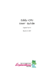
LT6
Protection and Intelligence Combined
File 9110
CONTENTS
Motor Protection ....................................................................................................... 2-3
Functions .................................................................................................................. 4-5
Characteristics .......................................................................................................... 6-9
Tripping Curves .................................................................................................... 10-11
Catalog Numbers .................................................................................................. 12-13
Mounting Dimensions ........................................................................................... 14-15
Application Diagrams ........................................................................................... 16-21
Glossary ...................................................................................................................... 22
This document provided by Barr-Thorp Electric Co., Inc. 800-473-9123
www.barr-thorp.com
LT6 Multifunction Protection Relays
Motor Protection
Operating conditions
There are many possible causes of electric motor failure. One of the most common, and which is often accidental, is the
utilization of motors beyond the operating limits defined by the manufacturer or in abnormal ambient conditions.
A statistical survey covering 9000 incidents of motor failure, gave the following results :
Overloads (1)
30 %
Operating conditions (example: corrosive atmosphere)
19 %
Phase failure
14 %
Bearing failure
13 %
Aging (example: ambient temperature too high) (1)
10 %
Rotor faults
5%
Miscellaneous
9%
These faults are related to motors with a power rating of 37 kW (50 hp) or more.
(1) An examination of the above results shows that, in more than 40 % of cases, the fault is due to the effects of heating.
Leaving aside the replacement of wearing parts, such as bearings, slip rings, brushes, etc., the life of an electric motor
is linked to that of its insulation. Provided that the temperature rise limit is not exceeded, the life expectancy of insulating
materials is extremely long. It is decreased by approximately one half for an excess temperature rise of 10 °C (18 °F).
The operating temperature limit TL of an insulating material depends on the type of material and is the sum of the ambient
air temperature AT (cooling air), the temperature rise limit TRL and an additional temperature rise value ATR considered
necessary because the measurement of winding resistance variation does not determine the temperature of the hottest
part of the motor winding, but only gives an average value for temperature rise.
The diagram below defines the standardized limits for different classes of insulation. In all cases, the normal ambient
cooling air temperature is fixed at 40 °C (104 °F).
°F
°C
356
180
329
311
165
155
284
140
266
257
248
239
130
125
120
115
212
100
176
80
140
60
104
40
68
20
32
0
ATR
TRL
TL
AT
E
B
F
Insulation Classes
2
This document provided by Barr-Thorp Electric Co., Inc. 800-473-9123
www.barr-thorp.com
HA
LT6 Multifunction Protection Relays
Motor Protection
The rated power of a motor corresponds to its temperature rise limit for an ambient temperature of 40 °C (104 °F). The
temperature rise limits for the different parts of a machine are given in the following table, which is an extract from IEC
publication 34-1.
Temperature rise limit
Insulation class
B
F
H
Insulated winding (measurement by resistance)
°C/°F
80/176
100/212
125/257
Commutators and slip-rings
°C/°F
80/176
90/194 (1)
100/212 (1)
Bearings
°C/°F
60/140
60/140 (2)
60/140 (2)
When a motor is used at an ambient air temperature other than the normal value, its temperature rise limit should be
modified in order to maintain the same maximum temperature limit. The result is that the motor operational power is no
longer the same as its rated power.
Also, the altitude of the installation, if this is above 1000 m (3281 ft), affects the cooling and increases the temperature
rise.
The following table gives the ratio between operational power and rated power, according to the operating conditions, for
a given ambient temperature. It corresponds to insulation class B.
Operational power / Rated power in watts
Altitude
m
ft
Ambient air temperature (AT)
30 °C
35 °C
40 °C
(86 °F) (95 °F)
(104 °F)
1000
3281
1.07
1.04
1.00
0.96
0.92
0.87
0.82
1500
4922
1.04
1.01
0.97
0.93
0.89
0.84
0.79
2000
6562
1.01
0.98
0.94
0.90
0.86
0.82
0.77
2500
8203
0.97
0.95
0.91
0.87
0.84
0.79
0.75
3000
9843
0.93
0.91
0.87
0.84
0.80
0.76
0.71
3500
11,484
0.89
0.86
0.83
0.80
0.76
0.72
0.68
4000
13,124
0.83
0.81
0.78
0.75
0.72
0.68
0.64
45 °C
50 °C
(113 °F) (122 °F)
55 °C
(131 °F)
60 °C
(140 °F)
The values shown in the above table are for guidance only. In effect, the derating of a motor depends on its size, insulation
class, method of construction (self-ventilated or forced ventilation, enclosure type), and varies according to the
manufacturer.
Also, in addition to the normal ambient conditions, the rated power of a motor is defined by the manufacturer for continuous
duty S1. This covers continuous operation of sufficient duration to enable the motor to reach a steady temperature. It is
this value of rated power that is normally shown on the motor plate.
There are other standardized types of duty, such as temporary duty S2, or intermittent periodic duty type S3, S4 and S5,
for which the motor manufacturer defines an operational power appropriate to each and different from the rated power.
(1) For temperature rise limits of 90 °C (194 °F) and 100 °C (212 °F) the brushes must be selected with the agreement
of the motor manufacturer.
(2) These limit values may be exceeded depending on the quality of the grease used and the applied loads.
3
This document provided by Barr-Thorp Electric Co., Inc. 800-473-9123
www.barr-thorp.com
LT6 Multifunction Protection Relays
Functions
The LT6 is designed for the control, monitoring, and protection of AC motors.
Product functions not using serial link communication
The LT6 protects against
- thermal overloads by monitoring motor currents: up to 25 full load amps with internal current transformers;
greater than 25 full load amps with external current transformers,
- overheating of motors with embedded PTC thermistor probes,
- phase unbalance and phase loss,
- earth (ground) fault.
It provides
- control of up to two power contactors for non-reversing, reversing, two-speed, and star-delta motor starting,
- fault signalling via an internal output relay and a 7-segment LED display.
LT6-P0M005FM
Using serial link communication
The LT6 may be set to protect against
- thermal overloads by monitoring motor currents: up to 25 full load amps with internal current transformers;
greater than 25 full load amps with external current transformers,
- overheating of motors with embedded PTC thermistor probes,
- phase unbalance and phase loss,
- earth (ground) fault,
- underload,
- prolonged starting time,
- overtorque and locked rotor,
- phase reversal,
- low power factor.
It provides
- control of one or two power contactors for non-reversing, reversing, two-speed, and star-delta motor starting,
- fault signalling via an output relay and a 7-segment LED display,
- voltage limitation by monitoring voltage between phases,
- signalling in the event of exceeding the short-circuit current,
- thermal alarm,
Bus communication
- provides information exchange between the LT6 and PLC or personal computer:
- instantaneous values (voltage, current per phase, frequency, power factor, thermal state of motor stator and copper
windings),
- data log of 5 previous trip incidents (causes and remedies),
- maintenance statistics, cause of trip statistics,
- operating and alarm states.
Physical features
•
•
•
•
•
•
•
•
•
•
•
•
Power input terminals from the contactor and power output terminals to the motor.
16-pin plug-in connector for monitoring protection inputs.
11-pin plug-in connector for outputs for contactor coil, thermal alarm, and fault signalling.
5-pin plug-in connector for ground fault current transformer and PTC thermistor probes.
Two rotary dials for selection of motor full load current from 20% to 109% of the maximum rated current
(1 A, 5 A, or 25 A) of the LT6 relay.
Rotary dial for selection of Class 5 (10 A), 10, 15, 20, 25, or 30 thermal overload protection.
DIP switch for selection of:
Bus communication address
UNI-TELWAY™ or JBUS/MODBUS® protocol
Manual or automatic thermal overload reset
Enable local (front face) or line (serial communication link) thermal overload settings
Sealable transparent cover eliminates tampering with local front cover settings.
7-segment display for fault indication.
"Test" button (opens N/C overload trip contact and closes N/O fault signal contact).
Manual "Reset" button.
SUB-D Serial interface port for bus communication.
For use with personal computer running Microsoft Windows 3.1 or Windows 95 with Configuration Software
Kit LA9P620 (includes RS232 cable and software)
For use with PLC or MAGELIS™ XBT terminal with XBT-L100 programming software
4
This document provided by Barr-Thorp Electric Co., Inc. 800-473-9123
www.barr-thorp.com
LT6 Multifunction Protection Relays
Functions
LT6 configuration table
Functions
Protection
Parameters
preset and
function
enabled at
factory
Ability to
enable or
disable by
serial link
Thermal overload
YES
Parameters
Description
Factory settings
Ir (% rating)
Overload class
Overload alarm
20 %
5
100 %
Factory installed
1 kΩ resistor
to disable function
Adjustment
range accessible
via serial link
communication
20 to 109 % (1)
5,10,15,20,25,30 (1)
0 to 100 %
Overheating via
PTC thermistors
YES
—
Enable or disable
Phase unbalance
and phase failure
YES
Id (% I rms average (2)) 30 % I average
Start inhibit
0.7 sec.
Time before
5 sec.
tripping
10 to 30 %
0 to 10 sec.
0 to 10 sec.
Earth (ground) fault
YES
YES
I∆r
Time before
tripping
30 A
5 sec.
0.3 to 30 A
0 to 5 sec.
Prolonged starting
time
YES
ISD (% Ir)
Starting
time
150 % Ir
10 sec.
100 to 500 % Ir
0 to 30 sec.
Undercurrent
YES
IV (% Ir)
Time before
tripping
30 % Ir
10 sec.
30 to 90 % Ir
0 to 30 sec.
Torque limitation
YES
ILC (% Ir)
Time before
tripping
200 % Ir
10 sec.
150 to 800 % Ir
0 to 30 sec.
Cos ϕ
(power factor)
YES
Cos ϕ
Time before
tripping
0.1
10 sec.
-1 to 1
0 to 10 sec.
Phase rotation
YES
—
Disabled
Enable or disable
direction monitoring
(1) These values can be activated and adjusted from the front face of the relay when set to “Local adjust”.
(2) The average rms current is equal to the average current value of the 3 phases.
Complementary
functions
Parameters
preset and
function
enabled at
factory
Voltage threshold
detection
(3) Thermal overload reset time is
based on calculated cooling time.
Cooling time of a self-cooled motor at
standstill is four times longer than the
cooling time of an external-cooled
motor.
Ability to
enable or
disable by
serial link
YES
Description
Factory setting
Adjustment
range accessible
via serial link
communication
Trip voltage
Time before
tripping
Reset voltage
Time before
resetting
70 % Un
10,000 sec.
68 to 120 % Un
0 to 100,000 sec.
90 % Un
10,000 sec.
68 to 120 % Un
0 to 100,000 sec.
Short-circuit
detection
YES
Isc
15 x lr peak
–
Automatic
reset
YES
Time before reset
Iron θ °C before
reset
0 sec.
100 % θn
0 to 1000 sec.
0 to 100 % θn
Motor control
YES
Control of
outputs
A and B
Reversing
Reversing
Independent
2-stage
Motor
cooling
YES
Cooling method
for motor
Self-cooled (3)
Self-cooled or
external-cooled (3)
5
This document provided by Barr-Thorp Electric Co., Inc. 800-473-9123
www.barr-thorp.com
LT6 Multifunction Protection Relays
Characteristics
Environment
Conforming to standards
IEC 947-4-1, IEC 34-11, IEC 755,
VDE 0106, VDE 0660
European community directives
marking
Meets the essential requirements of Low Voltage equipment (LV)
& Electromagnetic Compatibility (EMC).
Approvals
UL 508, CSA, PTB
Protective treatment
“TH” (Tropical Finish)
Degree of protection
Conforming to IEC 947-1
IP 20 (1)
Pollution degree
Conforming to IEC 664
3
Shock resistance
Conforming to IEC 68-2-27
15 gn, 11 milliseconds
Vibration resistance
Conforming to IEC 68-2-6
2 gn (3 to 100 Hz)
Ambient air temperature
around the device
Storage
°C
°F
- 35 to + 85
- 31 to + 185
Operation
°C
- 20 to + 70
- 4 to + 158
Flame resistance
°F
Conforming to UL 94
Maximum operating altitude
m
ft
2000
6562
In relation to normal
vertical mounting plane
4.65 in.
118 mm
Operating position
V0
3.55 in.
90 mm
Resistance to
electrostatic discharge
Conforming to IEC 1000-4-2 level 3
kV
8
Resistance to
electromagnetic interference
Conforming to IEC 1000-4-3 level 3
V/m
10
Resistance to
fast transient currents
Conforming to IEC 1000-4-4 level 4
kV
2
Resistance to conducted
radio-frequency disturbances
Rated undissipated
pulse withstand (U imp)
5.15 in.
131 mm
Conforming to IEC 1000-4-6 level 3
Conforming to IEC 947-1
kV
6
Rated dissipated
pulse withstand
Conforming to IEC 1000-4-5 level 3
Resistance to low frequency
disturbances - supply harmonics
Conforming to IEC 947-2 Appendix F
Clause F4.1
Resistance to micro-breaks
Conforming to IEC 1000-4-11
(1) Only applicable when power cabling to relay exceeds the following sizes:
1.5 mm2 (16 AWG) fitted with cable end or 2.5 mm2 (14 AWG) not fitted with cable end.
6
This document provided by Barr-Thorp Electric Co., Inc. 800-473-9123
www.barr-thorp.com
LT6 Multifunction Protection Relays
Characteristics
Power circuit characteristics—terminals L11, L21, L31, L15, L25, L35, 2T1, 4T2, 6T3
Relay type
LT6-P0M005FM
LT6-P0M025FM
V
110 to 600 VAC
110 to 600 VAC
V
690 VAC
690 VAC
Operating frequency
Hz
50/60 (1)
50/60 (1)
Rated operational current
A
0.2 to 5 (2)
5 to 25
1 or 2 conductors
mm2
AWG
1.5 to 6
16 to 10
Stranded cable w/out cable end 1 or 2 conductors
mm2
AWG
1.5 to 6
16 to 10
Stranded cable with cable end
mm2
AWG
1.5 to 4
16 to 12
N.m
lb-in
1.7
15
Operating voltage range
Rated insulation voltage (Ui)
Conforming to IEC 947-1
Cabling
Solid cable
1 or 2 conductors
Terminal tightening torque
Short-circuit protection
By circuit breaker
≤1A
1 to 5 A
>5A
By fuses
Select in accordance with
National Electrical Code
Select in accordance with
National Electrical Code
RK5 - 4 Amp. max.
RK5 - 20 Amp. max.
Max. 400 % of motor FLA
Max. 400 % of motor FLA
Control circuit supply characteristics—terminals A1, A2
Rated insulation voltage (Ui)
Conforming to IEC 947-1
V
380 VAC
V
90 to 276 VDC
90 to 276 VDC - 50/60 Hz
1 or 2 conductors
mm2
AWG
0.5 to 1
20 to 18
Stranded cable w/out cable end 1 or 2 conductors
mm2
AWG
0.5 to 1
20 to 18
Stranded cable with cable end
1 conductor
mm2
AWG
0.5 to 1
20 to 18
2 conductors
mm2
AWG
0.5 to 0.75
20
N.m
lb-in
0.7
6.5
Operating voltage
Cabling
Plug-in connector
Solid cable
Terminal tightening torque
Discrete input characteristics—terminals I1, I2, I3, I4, I5, I6, I7, I8, C1, C2 (see "Control circuit supply characteristics" for
cabling and tightening torques)
Rated insulation voltage (Ui)
Operating voltage
Current consumption
Input impedance
Conforming to IEC 947-1
Minimum transient value
V
V
mA
kΩ
250 VAC
90 to 15 VDC; 90 to 276 VAC - 50/60 Hz
≥ 1 (changing from 0 state to 1 state in t ≥ 4 ms)
56
(1) For use with 110 to 690 V - 50/60 Hz AC motors only. Not approved for use with DC motors or variable speed drives.
(2) For motor full load currents > 25 A, use LT6P0M005FM with customer-provided external current transformers with 1 A or 5 A secondary outputs.
7
This document provided by Barr-Thorp Electric Co., Inc. 800-473-9123
www.barr-thorp.com
LT6 Multifunction Protection Relays
Characteristics
Discrete output characteristics—terminals 95, 96, 01, 02 (see "Control circuit supply characteristics"
for cabling and tightening
torques)
Rated insulation voltage (Ui)
Conforming to IEC 947-1
Type of output
Relay
Associated fuse protection
Conforming to IEC 947-5
V
380 VAC
1 N/O per channel
A
6 A max. type RK5
Rated voltage
V
250 VAC
Permissible power
for category AC-15
Associated with contactor
VA
500 (Ie = 0.5 A, Ue = 250 VAC, Ith = 5 A, cos ϕ = 0.4,
for 100,000 operations)
LC1-K, LC2-K, LC7-K, LC8-K
LC1-D09 to D95, LC1-F115 to F150
Rated voltage
V
30 VDC
Permissible power
for category DC-15
Associated with contactor
VA
50 (Ie = 0.5 A, Ue = 30 VDC, Ith = 5 A, L/R ≤ 25 ms
for 100,000 operations)
LP1-K, LP2-K, LP1-D09 and D12
LP1-D18 to D32 (with LA4-DC1U or DC2U)
LP1-D40 to D80 (with LA4-DC3U)
AC loads
DC loads
Signalling output characteristics—terminals 97, 98, 93, 94 (see "Control circuit supply characteristics"
for cabling and tightening
torques)
Rated insulation voltage (Ui)
Conforming to IEC 947-1
V
380 VAC
Type of output
Relay
Associated fuse protection
Conforming to IEC 947-5
A
4 A max. Type RK5
Current limit
At U = 5 VDC
mA
10
Rated voltage
V
250 VAC
Permissible power
for category AC-15
Associated with contactor
W
250 (Ie = 0.2 A, Ue = 250 VAC, Ith = 2 A,
300,000 operations for resistive load)
LC1-K, LC2-K, LC7-K, LC8-K with suppressor block LA4-KE
Rated voltage
V
Permissible power
for category DC-15
Associated with contactor
W
1 N/O per channel
AC loads
DC loads
30 VDC
50 (Ie = 0.2 A, Ue = 30 VDC, Ith = 2 A,
300,000 operations for resistive load)
LP1-K, LP2-K with suppressor block LA4-KC
External current transformer characteristics (Customer provided. Must have 1 A or 5 A secondary
Conforming to standards
IEC 185, IEC 71
Accuracy class
5P
Accuracy limit factor
15
output)
8
This document provided by Barr-Thorp Electric Co., Inc. 800-473-9123
www.barr-thorp.com
LT6 Multifunction Protection Relays
Characteristics
PTC thermistor probes
DA1-TT•••
Probe characteristics—terminals T1, T2 (see "Control circuit supply characteristics" for cabling and tightening torques)
Conforming to standards
IEC 34-11, mark A
Resistance
At 25 °C
Ω
3 x 250 in series
Rated operational voltage (Ue)
Per probe
V
2.5 VDC max.
kV
2.5
Rated insulation voltage (Ui)
Insulation
Between probes
mm
in
250
10
Between probe and motor
terminal block
m
ft
1
3
Guaranteed operating zones : examples with 3 probes type DA1-TT••• (250 Ω at 25 °C) connected in series, conforming
to IEC 34-11, mark A.
Resistance
(ohms)
10 000
4000
Trip zone
1650
1500
1000
750
Reset zone
1
1
3 probes type DA1-TT•••
(250 Ω at 25 °C) in series
100
NOT : nominal operating
temperature
20
Trip zone
on short-circuit probes
10
Trip control
device
-20
0
NOT - 5 °C
NOT
NOT + 5 °C
NOT + 15 °C
Reset control
device
NOT - 20 °C
Cable lengths
Reinforced
Temperature
(°C)
9
This document provided by Barr-Thorp Electric Co., Inc. 800-473-9123
www.barr-thorp.com
LT6 Multifunction Protection Relays
Tripping Curves
Cold state curves (1)
t (s)
10000
1000
100
Class 30
Class 25
Class 20
10
Class 15
Class 10
Class 5 (10 A)
I/Ir
1
1 1.12
1.5
2
3
4
5
6
7
8
(1) Tripping time accuracy : ± 8 % to 7.2 x I/Ir.
10
This document provided by Barr-Thorp Electric Co., Inc. 800-473-9123
www.barr-thorp.com
LT6 Multifunction Protection Relays
Tripping Curves
Hot state curves (1)
t (s)
10000
1000
100
10
Class 30
Class 25
Class 20
Class 15
Class 10
Class 5 (10 A)
I/Ir
1
1 1.12
1.5
2
3
4
5
6
7
8
(1) Tripping time accuracy : ± 8 % to 7.2 x I/Ir.
11
This document provided by Barr-Thorp Electric Co., Inc. 800-473-9123
www.barr-thorp.com
LT6 Multifunction Protection Relays
Catalog Numbers
3-pole multifunction protection relays
Operational current
A
Catalog Number
0.2 to 1 (use terminals L11-L21-L31)
LT6-P0M005FM
1 to 5 (use terminals L15-L25-L35)
LT6-P0M005FM
5 to 25
LT6-P0M025FM
LT6-P0M005FM
For AC motor full load currents > 25 A, use LT6P0M005FM with customer provided external current transformers
with 1 A or 5 A secondary outputs.
Configuration software and user's manual
Description
For use
with
Catalog Number
Configuration software kit:
- 3"1/2 diskette,
- 2 meter RS232 cable
All ratings of relay
PC minimum requirements:
386 SX with Windows 3.1
LA9-P620
User's manual — USA Edition
9110IM9701
Earth fault toroids (ground fault current transformers)
Products marketed under the Merlin Gerin brandname. For ordering references, please refer to our Merlin Gerin
“Low voltage distribution 95/96” catalog, pages D72 to D74
Sensitivity
Internal Ø
Type
Catalog Number
of toroid
mm
0.3 to 30 A
30
TA30
50437
50
PA50
50438
80
IA80
50439
120
MA120
50440
200
SA200
50441
300
GA300
50442
46
POA
50485
110
GOA
50486
Note: Merlin Gerin earth fault toroids may be substituted with GFCT with 1000:1 ratio.
12
This document provided by Barr-Thorp Electric Co., Inc. 800-473-9123
www.barr-thorp.com
LT6 Multifunction Protection Relays
Catalog Numbers
PTC thermistor probes
DA1-TT•••
Description
Nominal
operating
temperature
(NOT)
°C
Sold in
lots of
Catalog Number
Triple probes
90
10
DA1-TT090
110
10
DA1-TT110
120
10
DA1-TT120
130
10
DA1-TT130
140
10
DA1-TT140
150
10
DA1-TT150
160
10
DA1-TT160
170
10
DA1-TT170
13
This document provided by Barr-Thorp Electric Co., Inc. 800-473-9123
www.barr-thorp.com
LT6 Multifunction Protection Relays
Mounting Dimensions
Protection relays LT6-P
LT6-P0M•••FM
on 35 mm " DIN rail
4.33 in.
110 mm
4.65 in.
118 mm
Drilling pattern for panel mounting with M4 or ANSI #8 machine screws
5.15 in.
131 mm
3.55 in.
90 mm
2.12 in.
54 mm
AF1EA4 Clip
For M4 screws
on pre-slotted
mounting plate
AM1-PA
LT6-P0M•••FM weight: 1.03 kg (2.3 lbs).
Earth fault toroids
TA30, PA50
IA80, MA120, SA200
Ø5
c2
21
b1
H
Øb
b2
b
H
K
b1
4
16
8
2xØ4.5
2xØ4.5
Øc
29
c1
Type
TA30
PA50
Dimensions in millimeters
b
b1
Øc
83
53
30
109
66
50
c1
60
87
c2
31
45
H
50
60
Type
IA80
MA120
SA200
Øc
a
J
G
c1
a1
Dimensions in millimeters
a
a1
Øb b1
b2
26.5 44
122 80
55
26.5 44
164 80
55
29
46
256 120 90
Øc
80
120
196
c1
150
190
274
14
This document provided by Barr-Thorp Electric Co., Inc. 800-473-9123
www.barr-thorp.com
G
35
35
37
H
65
65
104
J
126
166
254
K
40
40
60
LT6 Multifunction Protection Relays
Mounting Dimensions
13.54 in.
344 mm
GA300
11.77 in.
299 mm
1.14 in.
29 mm
Øb
POA, GOA
Øc
a
4xØ5
G
Type
POA
GOA
Dimensions in millimeters
a
Øb
72
148
78
224
Øc
46
110
G
57
76
15
This document provided by Barr-Thorp Electric Co., Inc. 800-473-9123
www.barr-thorp.com
LT6 Multifunction Protection Relays
Application Diagrams
Motor control: full-voltage non-reversing starting (channels A and B set for reversing or independent control)
Control from front face of relay
Control via discrete inputs of relay
– KM1
Reserved
I8
Discrete input E
I7
Discrete input D
– KM1
Motor
stop
Channel B
Discrete input C
I5
Stop channels A and B
I4
Start channel B
I3
Start channel A
I2
Local or serial communication
control of A and B
I1
Reset
O2
97
Fault
signalling 98
Motor
start
93
Alarm
Control
supply
(1)
A2
A1
I8
Discrete input E
I7
Discrete input D
I6
Discrete input C
I5
Stop channels A and B
I4
Start channel B
I3
Start channel A
I2
Local or serial communication
control of A and B
I1
Reset
O1
Channel B
O2
97
Fault
signalling 98
93
Alarm
C1 Common 1 (-)
1 kΩ
C2 Common 2 (-)
PTC probes T1
T2
NC
Earth fault H1
toroid H2
Control
supply
(1)
A2
A1
1 kΩ
PTC probes T1
T2
NC
H1
Earth fault
toroid H2
(2) – KM1
(2) – KM1
1L1
1L1-L11-L15
2T1
3L2
3L2-L21-L25
4T2
5L3
5L3-L31-L35
6T3
M
3
1L1
1L1-L11-L15
2T1
3L2
3L2-L21-L25
4T2
5L3
5L3-L31-L35
6T3
Control via serial link communication (UNI-TELWAY, Jbus/Modbus)
Maintained
stop (3)
D1
D2
D3
D4
95
Channel
A
Reserved
I8
Discrete input E
I7
Discrete input D
I6
Discrete input C
I5
Stop channels A and B
I4
Start channel B
I3
Start channel A
I2
Local or serial communication
control of A and B
I1
Reset
– KM1
96
O1
Channel B
O2
97
Fault
signalling 98
93
Alarm
94
C1 Common 1 (-)
C2 Common 2 (-)
Control
supply
(1)
– KM1
96
94
94
C1 Common 1 (-)
C2 Common 2 (-)
Channel
A
Reserved
96
O1
I6
95
D1
D2
D3
D4
D1
D2
D3
D4
95
Channel
A
Motor
stop
Motor
start
A2
A1
1 kΩ
PTC probes T1
T2
NC
Earth fault H1
toroid H2
(2) – KM1
1L1
1L1-L11-L15
2T1
3L2
3L2-L21-L25
4T2
5L3
5L3-L31-L35
6T3
M
3
(1) For DC control supplies inputs I1 to I8 must be connected to the positive line.
(2) Disconnecting means and short circuit protection must comply with National Electrical Code and local codes.
(3) Local maintained stop must be connected when serial link is used without local stop push button.
16
This document provided by Barr-Thorp Electric Co., Inc. 800-473-9123
www.barr-thorp.com
M
3
LT6 Multifunction Protection Relays
Application Diagrams
Motor control: full-voltage non-reversing starting
Control via serial link communication with signalling, earth fault toroid, PTC probes, state of power components
Channels A and B set for reversing or independent control
Possible to control the motor via discrete input (“local” position) or by serial link communication
Maintained
stop (3)
D1
D2
D3
D4
95
Channel
A
Reserved
– Q1
– KM1
I8
Discrete input E
I7
Discrete input D
I6
Discrete input C
I5
Stop channels A and B
I4
Start channel B
I3
Start channel A
I2
Local or serial communication
control of A and B
I1
Reset
O1
Channel B
O2
Motor stop
Motor start
Line
– KM1
96
97
Fault
signalling 98
Tripped
93
Alarm
Overload
94
Local
C1 Common 1 (-)
C2 Common 2 (-)
A2
Control
supply
(1)
A1
PTC probes T1
T2
NC
Earth fault H1
toroid H2
(2) – KM1
1L1
1L1-L11-L15
2T1
3L2
3L2-L21-L25
4T2
5L3-L31-L35
5L3
6T3
U
V
M
3
θ°C
W
Power terminal connections for single-phase motor applications
A2
A1
(2)
– KM1
1L1-L11-L15
2T1
3L2-L21-L25
4T2
5L3-L31-L35
6T3
M
(1) For DC control supplies the inputs I1 to I8 must be connected to the positive line.
(2) Disconnecting means and short circuit protection must comply with the National Electrical Code and local codes.
(3) Local maintained stop must be connected when serial link is used without local stop push button.
17
This document provided by Barr-Thorp Electric Co., Inc. 800-473-9123
www.barr-thorp.com
LT6 Multifunction Protection Relays
Application Diagrams
Motor control: full-voltage reversing starting
Control via discrete inputs of relay
Channels A and B set for reversing control
95
D1
D2
D3
D4
Control via front face of relay
Channels A and B set for reversing control
D1
D2
D3
D4
95
Channel
A
Reserved
I8
Discrete input E
I7
Discrete input D
I6
Discrete input C
Stop channels A and B
I4
Start channel B
Start channel A
Discrete input E
I7
Discrete input D
I6
Discrete input C
I5
Stop channels A and B
Reverse
start
I4
Start channel B
Forward
start
I3
Start channel A
I2
Local or serial communication
control of A and B
93
I1
Reset
94
C1 Common 1 (-)
Forward
start
– KM1
Fault
signalling
I2
Local or serial communication
control of A and B
I1
Reset
Reverse
start
Motor
stop
– KM1
97
– KM1
– KM2
98
A2
A1
C2 Common 2 (-)
1 kΩ
PTC probes T1
T2
NC
Earth fault H1
toroid H2
A2
Control
supply
(1)
A1
Fault
signalling
– KM1 – KM2
O2
97
98
93
Alarm
94
1 kΩ
PTC probes T1
T2
NC
Earth fault H1
toroid H2
(2)
(2)
– KM1
– KM1
1L1
L11
1L1-L11-L15
2T1
3L2
L21
3L2-L21-L25
4T2
M
1L1
L11
1L1-L11-L15
2T1
3L2
L21
3L2-L21-L25
4T2
5L3
L31
5L3-L31-L35
6T3
3
6T3
L31
5L3-L31-L35
– KM2
– KM2
Control via serial link communication
Channels A and B set for independent control
Maintained
stop (3)
D1
D2
D3
D4
95
Channel
A
Reserved
I8
Discrete input E
I7
Discrete input D
I6
Discrete input C
I5
Stop channels A and B
I4
Start channel B
Start channel A
I2
Local or serial communication
control of A and B
I1
Reset
C2 Common 2 (-)
A2
A1
– KM2 – KM1
96
O1
Channel
B
I3
C1 Common 1 (-)
Control
supply
(1)
– KM2 – KM1
96
O1
Channel
B
Alarm
C2 Common 2 (-)
5L3
– KM2
O2
– KM2
C1 Common 1 (-)
Control
supply
(1)
I8
O1
I5
I3
96
Motor
stop
Channel
B
Channel
A
Reserved
Fault
signalling
– KM1 – KM2
O2
97
98
93
Alarm
94
1 kΩ
PTC probes T1
T2
NC
Earth fault H1
toroid H2
(2)
– KM1
1L1
L11
1L1-L11-L15
2T1
3L2
L21
3L2-L21-L25
4T2
5L3
L31
5L3-L31-L35
6T3
M
3
– KM2
(1) For DC control supplies the inputs I1 to I8 must be connected to the positive line.
(2) Disconnecting means and short circuit protection must comply with National Electrical Code and local codes.
(3) Local maintained stop must be connected when serial link is used without local stop push button.
18
This document provided by Barr-Thorp Electric Co., Inc. 800-473-9123
www.barr-thorp.com
M
3
LT6 Multifunction Protection Relays
Application Diagrams
Motor control: full-voltage reversing starting with measurement of cos ϕ and voltage
Control via serial link communication
Channels A and B set for reversing control
Maintained
stop (3)
D1
D2
D3
D4
95
Channel
A
Reserved
230 V
0V
– KM2
– KM1
– KM1
– KM2
96
C2 Common 2 (–)
I8
Discrete input E
I7
Discrete input D
I6
Discrete input C
I5
Stop channels A and B
I4
Start channel B
O1
Channel
B
O2
97
Fault
Start channel A
signalling
Local or serial com98
I2
munication control of A & B
Reset
I1
93
C1 Common 1 (–)
Alarm
94
A2
I3
Control
supply
(1)
A1
230 V
0V
(2)
1L1
3L2
5L3
1 kΩ
PTC probes T1
T2
NC
Earth fault H1
toroid H2
– KM1
L11
1L1-L11-L15
2T1
L21
3L2-L21-L25
4T2
5L3-L31-L35
L31
6T3
M
3
(1) For DC control supplies the inputs I1 to I7 must be connected to the positive line.
(2) Disconnecting means and short circuit protection must comply with National Electrical Code and local codes.
(3) Local maintained stop must be connected when serial link is used without local stop push button.
19
This document provided by Barr-Thorp Electric Co., Inc. 800-473-9123
www.barr-thorp.com
LT6 Multifunction Protection Relays
Application Diagrams
Motor control: star-delta starting (channels A and B set for 2-stage control)
Control via discrete inputs of relay
D1
D2
D3
D4
95
Channel
A
Reserved
Motor
stop
Motor
start
I8
Discrete input E
I7
Discrete input D
– KM3
– KM1 – KM2
I6
Discrete input C
Stop channels A & B
I4
Start channel B
I3
Start channel A
Local or serial communi97
Fault
cation control of A & B
signalling
Reset
98
I1
– KM3
O1
I5
I2
– KM1
96
Channel
B
– KM1
– KM3
O2
C1 Common 1 (–)
93
C2 Common 2 (–)
Control
supply
(1)
Alarm
A2
94
A1
(2)
1L1
2T1
L11
1L1-L11-L15
3L2
4T2
L21
3L2-L21-L25
5L3
1 – KM1 2
1 kΩ
PTC probes T1
T2
NC
Earth fault H1
toroid H2
4
5
6
1 – KM2 2
U1
3
4
V1
6
W1
5
6T3
L31
5L3-L31-L35
3
U2
M
3
V2
W2
1 – KM3 2
3
4
5
6
Control via serial link communication
Maintained
stop (3)
D1
D2
D3
D4
95
Channel
A
Reserved
I8
Discrete input E
I7
Discrete input D
– KM3
– KM1 – KM2
I6
Discrete input C
Stop channels A & B
I4
Start channel B
I3
Start channel A
Local or serial communi97
Fault
cation control of A & B
signalling
Reset
98
I1
– KM3
O1
I5
I2
– KM1
96
Channel
B
– KM1
– KM3
O2
C1 Common 1 (–)
C2 Common 2 (–)
Control
supply
(1)
A2
3L2
5L3
94
A1
1 kΩ
PTC probes T1
T2
NC
Earth fault H1
toroid H2
(2)
1L1
93
Alarm
L11
1L1-L11-L15
L21
3L2-L21-L25
L31
5L3-L31-L35
2T1
4T2
6T3
1 – KM1 2
3
4
5
6
1 – KM2 2
U1
3
4
V1
5
6
W1
U2
M
V2
3
W2
1 – KM3 2
3
4
5
6
(1) For DC control supplies the inputs I1 to I7 must be connected to the positive line.
(2) Disconnecting means and short circuit protection must comply with National Electrical Code and local codes.
(3) Local maintained stop must be connected when serial link is used without local stop push button.
20
This document provided by Barr-Thorp Electric Co., Inc. 800-473-9123
www.barr-thorp.com
LT6 Multifunction Protection Relays
Application Diagrams
Motor control: star-delta starting with adjustable time delay
Control via serial link communication
Channels A and B set for 2-stage control
Maintained
stop (3)
D1
D2
D3
D4
95
Channel
A
Reserved
230 V
0V
– KM3
– KM1
– KM3
96
C2 Common 2 (–)
I8
– KM1
Discrete input E
I7
Discrete input D
I6
Discrete input C
O1
Channel
B
I5
Stop channels A and B
I4
Start channel B
– KM3
– KM2
– KM1
O2
97
Fault
Start channel A
signalling 98
I2 Local or serial communication control of A & B
I1 Reset
93
C1 Common 1 (–)
Alarm
94
A2
I3
Control
supply
(1)
230 V
A1
400 V
0V
0V
1 kΩ
PTC probes T1
T2
NC
Earth fault H1
toroid H2
(2)
1L1
L11
1L1-L11-L15
2T1
3L2
L21
3L2-L21-L25
4T2
5L3
5L3-L31-L35
L31
6T3
1 – KM1 2
3
4
5
6
1 – KM2 2
U1
3
V1
4
U2
M
V2
3
5
6
W1
W2
1 – KM3 2
3
4
5
6
(1) For DC control supplies the inputs I1 to I7 must be connected to the positive line.
(2) Disconnecting means and short circuit protection must comply with National Electrical Code and local codes.
(3) Local maintained stop must be connected when serial link is used without local stop push button.
21
This document provided by Barr-Thorp Electric Co., Inc. 800-473-9123
www.barr-thorp.com
LT6 Multifunction Protection Relays
Glossary
Glossary
PTC
Positive Temperature Coefficient. A thermistor resistor with a resistance
value which increases with temperature and which increases very rapidly
as the nominal operating temperature is reached.
RDF
Residual Differential Fault (earth leakage or ground fault)
rms
Root mean square value of a signal
I
Line current
Ir
Motor full load current
Id
Phase imbalance current (calculated value)
I∆
Residual differential fault current (earth leakage current)
I∆r
Set value of the residual differential fault current (earth leakage current)
Iv
Monitoring value of the underload current, a multiple of Ir
Imax
The highest value of the three phase currents
Imini
The lowest value of the three phase currents
Iav
Average value of the three phase currents
Isd
Monitoring threshold of the starting current, a multiple of Ir
ILC
Torque limitation (locked rotor) current
ICC
Short-circuit current
Discrete
On/Off
Θn
Nominal temperature of the iron circuit reached with I = Ir after an infinite
time
Θr
Set temperature for the thermal overload alarm
Cos ϕ
Power factor
Earth fault
Ground fault
Earth fault toroid
Ground fault sensor (zero sequence current transformer)
Un
Nominal voltage
22
This document provided by Barr-Thorp Electric Co., Inc. 800-473-9123
www.barr-thorp.com
LT6 Multifunction Protection Relays
Notes
23
This document provided by Barr-Thorp Electric Co., Inc. 800-473-9123
www.barr-thorp.com
.
Square D and
are registered trademarks of Square D Company.
MAGELIS™ is a trademark of Schneider Electric SA
Square D Company
P.O. Box 27446
Raleigh, N.C. 27611, USA
(919) 266-3671
MODBUS® is a registered trademark of AEG Schneider Automation Inc.
Catalog 9110CT9702 07/97 © 1997 Square D All Rights Reserved.
This document provided by Barr-Thorp Electric Co., Inc. 800-473-9123
www.barr-thorp.com