1
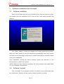
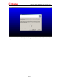
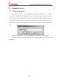
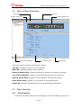
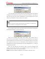
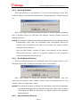
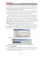
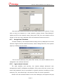
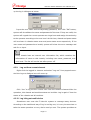
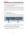
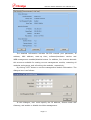
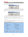
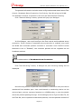
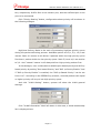
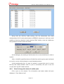
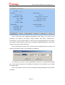
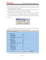
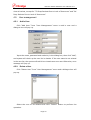
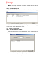
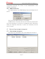
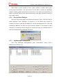
FBSWITCH1000 Series Network Switch
Fi-View-AL Software User Manual
Beijing Fibridge Co., Ltd.
Network Switch Software User Manual V1.0
Content
1.
Introduction .................................................................................. 2
2.
System Requirement ...................................................................... 3
2.1. Basic Requirement .......................................................................................3
2.2. Recommendation requirement .......................................................................3
3.
Software Installation and Uninstall ................................................... 4
3.1. Software Installation ....................................................................................4
3.2. Software Uninstall .......................................................................................4
4.
Operation Guide ............................................................................ 6
4.1. System Password ........................................................................................6
4.2. Main Interface Description ............................................................................7
4.3. Basic Operation ...........................................................................................7
4.3.1.
Add A Network ....................................................................................7
4.3.2.
Add Network Element ...........................................................................8
4.3.3.
Delete A Network .................................................................................9
4.3.4.
Delete Network Element........................................................................9
4.3.5.
Search Network Element .......................................................................9
4.3.6.
Change Network ................................................................................ 10
4.3.7.
Assign New IP Address ....................................................................... 11
4.3.8.
Login network element ....................................................................... 11
4.3.9.
Log out from current element .............................................................. 12
4.3.10. Log in/log out multi-device .................................................................. 12
4.3.11. Refresh the system information............................................................ 13
4.4. Chassis Management ................................................................................. 13
4.4.1.
View the status of current chassis ........................................................ 13
4.4.2.
View & Change the status of management module.................................. 13
4.4.3.
View & change the status of switch ports ............................................... 18
4.5. User management ..................................................................................... 22
4.5.1.
Add a User ........................................................................................ 22
4.5.2.
Delete a User .................................................................................... 22
4.5.3.
User information List .......................................................................... 23
4.6. SNMP Configuration ................................................................................... 23
4.6.1.
Set Trap Destination Address ............................................................... 23
4.6.2.
SNMP Parameter Set .......................................................................... 24
4.7. Alarm and log messages management.......................................................... 24
4.7.1.
Alarm message management............................................................... 24
4.7.2.
Pop up Alarm Dialogue........................................................................ 25
4.7.3.
Log Messages management ................................................................. 25
Page 1
Network Switch Software User Manual V1.0
1. Introduction
Beijing Fibridge Co., Ltd. summarized the experience of selling the American
broadband products since 1995 and synthesized the merits of different products
of the world-famous manufacturers. The series of products select the higher
quality device and develop meticulously for use. This series of products are
orientated in the broadband access system for its high-quality, high-stability
and low price. After being put up, the products can be used in the
telecommunication IP MAN broadband optical network solution for its steady
performance and powerful function. It interconnects a main board server,
repeater, hub, switch, or PC and another PC simply. The device adopts the
elaborately designed switch core, with high-speed non-blocking fabric and
ultra-broad switch bandwidth, to make sure data transmission and reception
has high stability. As an Ethernet access device, the device not only supports
IEEE802.3 10Base-T Ethernet and IEEE802.3u 100Base-Tx fast Ethernet
protocols, but also is compliant with IEEE 802.3x Flow Control, IEEE802.1Q
VLAN TAG, IEEE802.1p Qos and IEEE802.1D Spanning Tree protocols.
FBSWITCH1000 Series Network Switch provides four standard RJ45 jacks as
10/100Mbps Ethernet ports and one SC/FC/ST connector as fiber optic port
(F6-2114), or five standard RJ45 jacks as 10/100Mbps Ethernet ports
(F6-2105).
FBSWITCH1000 Series Network Switch supports WEB management, SNMP
software
management
and
RS-232
console
management.
Customers
conveniently view and configure all ports and management part via
management software, including the function of enable/disable a certain port,
setting the port force mode, link speed, duplex mode and ports speed limitation,
and resetting the management part, all 5 Ethernet ports or both. Some
functions, such as VLAN, port mirror and broadcast protection, are very
convenient and useful for high-level application.
More information about device, please read ‘FBSWITCH1000 Series
Network Switch Install & Operation User Manual’ for reference.
Page 2
Network Switch Software User Manual V1.0
2. System Requirement
2.1. Basic Requirement
□ Intel Pentium II 400,64MB RAM, 20MB Disk Space
□ Microsoft Windows 2000/XP Professional
2.2. Recommendation requirement
□ Intel Pentium III 500 or higher, 128MB RAM, 50MB disk space
Page 3
Network Switch Software User Manual V1.0
3.
Software Installation and Uninstall
3.1. Software Installation
Insert the CD-ROM disk into the CD-ROM driver. View the content of disk,
and double-click the installation file Fi-View-AL.exe, then install interface will
pops up.
Click “Next” button, choose the installed route and program group name,
then click “Next” button to copy the software and install files. After that, system
will auto set corresponding configuration. Do NOT close the pup-up DOS window
during the installation.
After installation, system will inquire whether restart the computer or not.
Recommend to restart the system.
NOTE: When you first install the software, the setup software will install MDAC
in your computer automatically.
3.2. Software Uninstall
Click “Uninstall” in the program group to uninstall Fi-View-AL program and
all components. System will pop up the uninstall window as below,
Page 4
Network Switch Software User Manual V1.0
User can also use “Add/Delete Program” in “Control Panel” to uninstall the
software.
Page 5
Network Switch Software User Manual V1.0
4.
Operation Guide
4.1. System Password
For higher security, the management software provides the system
password. Different from passwords stored in chassis, this password is just
saved in the management PC. User could select “System Password” from
“System” menu to enable or disable this function. When it is enabled, the user
is required to input system password as soon as management program starts
up.
The system password is null and disabled at the default configuration.
Clicking “Change System Password “in” System Menu can modify this
password.
Page 6
Network Switch Software User Manual V1.0
4.2. Main Interface Description
Title bar
Menu bar
Chassis Status Area
Shortcut buttons bar
Tree-view Catalogue
Ports Status Area
Status Bar
The main window consists of following 7 parts:
Title Bar: Display the title of current window.
Menu Bar: Display software menu options.
Shortcut Buttons Bar: Display all shortcut buttons for common functions.
Tree-View Catalogue: Display all managed devices in tree-view style.
Chassis Status Area: Display current status of the selected chassis.
Ports Status Area: Display current status of the selected port.
Status Bar: Display software status and corresponding information.
4.3. Basic Operation
4.3.1. Add A Network
Click the root node of the tree-view catalogue. Then click “Add” button of the
Page 7
Network Switch Software User Manual V1.0
shortcut menu bar, “Add network” window will pops up.
Fill in the name of the network then click “OK” button, and a new network
is added into the system and is shown in the tree-view catalogue. User also can
right-click the root node, choose “Add Network” from the popped menu or click
“Add” from “Operation” menu to add a new network.
Network: A group of chassis connected with each other or in same area.
Network element: A management switch chassis.
4.3.2. Add Network Element
Click a certain network then click “Add” button on the shortcut buttons bar.
“Add Network Element” window will pop up.
Input an IP address then press “OK” button, and system tries to
auto-connect with the chassis. If connection sets up successfully, a new network
element appears as a sub-node in the tree-view catalogue. And if the connection
fails, system will pop up the error information, which indicates the twist-pair
management port may be disconnected from the management PC, or that the
chassis does not exist.
Also, user can right-click the network node in tree-view catalogue and
choose “Add Network Element” from popped-up menu or click ”Add” from
operation menu to add a new network element.
Notice: the factory default IP address of the chassis is 192.168.0.216.
Page 8
Network Switch Software User Manual V1.0
4.3.3. Delete A Network
Click the network to be deleted in the tree-view catalogue, then click
“Delete” button in the shortcut buttons bar. “Delete Network” window will pop
up.
Click “Yes” button to delete the selected network and all elements affiliated
with it. Another way is to right-click the network, choose ”Delete” from the
popped-up menu.
Notice: If a network is deleted, all elements affiliated with it will also be deleted
automatically. After that, all information and configuration about the
network and its elements will NOT be recovered. So, please confirm
operation before doing it.
User can NOT delete, rename or add a new element to the network
“Discovered Devices”, which is a reserved network for the temporary
results of network-element-search.
4.3.4.
Delete Network Element
Click the network element to be deleted, then click “Delete” button in the
shortcut buttons bar. A dialogue box pops up for confirmation.
Click “Yes” button to delete the selected network element. User can
right-click the network node, choose “Delete” from the popped menu or click
“delete” from the “Operation” menu.
Notice: If a network element is deleted, all information, such as log messages
and alarm messages will be deleted permanently. After that, all these
information will NOT be recovered. So, please confirm the operation
before doing it.
4.3.5.
Search Network Element
Page 9
Network Switch Software User Manual V1.0
Fi-View-AL software gains the function of network element search for the
user convenience, which can search equipment in certain IP address range,
automatically or manually. As mentioned above, all search results are put into
the reserved network “Discovered Devices”.
System offers two search ways: automatic or manual. User can operate by
clicking “Automatic search” or “Manual search” from “Operation” menu or
right-click network “Discovered Devices” to achieve the function.
In automatic search manner, system will auto-search all IP addresses of
class C sub-net in which management PC resides, one by one. For instance, the
IP of management PC is 92.168.0.* (* is a integer within the range from 0 to 255),
system will search IP addresses from 192.168.0.0 to 192.168.0.255 automatically.
If the system finds a chassis’ IP address is in this range, the device will be added
into the network “Discovered Devices” as one of the search results.
Notice: the factory default IP address of the chassis is 192.168.0.216.
In manual search, the range of searching IP address is specified by operator.
System searches IP addresses in this range and if chassis is found, it will be
added into the network “Discovered Devices”. The dialogue box is as below:
The progress bar shows the progress of searching.
Device founded is added into the network “Discovered Devices”.
4.3.6. Change Network
In some instance, user maybe needs to change an element from a network
to another. Right-click the network element, select “Change Network”, then
system pops up a dialog box as below:
Page 10
Network Switch Software User Manual V1.0
User can move selected element to an existed network or a new one. If user
plan to move an element to a new network, please choose “New Network”
option and fill in the network name, then press “OK”, the new network will be
shown in the tree-view catalogue with the selected element moved in.
4.3.7. Assign New IP Address
In some instance, user maybe needs to assign a new ip address for an exist
element. Right-click the network element, select “Assign New IP”, then system
pops up a dialog box as below:
Fill in a new IP address, then press “OK” button, the new IP address will be
assigned to the selected element.
4.3.8.
Login network element
For high stability and security, the system adopts advanced user
management and ID validation mechanism. Only users with the correct user
name and password can be permitted to operate devices according to their
authority. So, user should log in the device firstly for further operation.
Double-click the element node in tree-view catalogue, and system will pop
Page 11
Network Switch Software User Manual V1.0
up the log in dialogue as below:
Input the user name and corresponding password, then click “OK” button,
system will do validate the name and password of the user. If they are valid, the
system will regard the current operator as a legal user and assign the authority
to the operator according to the user level. At this time, chassis and ports status
will be shown in chassis status area and ports status area respectively. If the
user name and password are invalid, system will show the error message and
ask for re-input.
Every chassis have an internal user information list, which contains the
information of users on this chassis, including user name, password, and
user level. The list will not be lost after power-off.
4.3.9.
Log out from current element
Right-click the logged-in element and select “Log-out” from popped menu.
And the log-out dialogue box will come up.
Click“Yes” to log out the current user from the network element After the
operation, this chassis and modules status are invisible. Log in again if view the
status of the chassis and all modules.
4.3.10. Log in/log out multi-device
Sometimes user uses the Fi-View-AL system to manage many devices.
According to the traditional way of log-in and log-out, it is very inconvenient to
take the same operation on very device one bye one. The system provides an
Page 12
Network Switch Software User Manual V1.0
effective way to achieve it. Select “Log in all devices” or “Log out of all devices”
from the menu
“System”, then a dialogue will pop up. The operation is familiar
with the log-in and log-out process on a single device.
4.3.11. Refresh the system information
If IP address of the management PC is accurately added into “Trap Target
Address” list of the chassis, the chassis and modules information will refresh
automatically on receiving the trap information. User also can achieve that by
clicking “Refresh” from “Operation” menu. And furthermore, system supports
Refresh-All-Device function by clicking “Refresh all devices” from “Operation”
menu.
4.4. Chassis Management
4.4.1.
View the status of current chassis
After log in the chassis successfully, the chassis status area will show the
real-time status of the chassis, including the status of each port configuration,
device ID number, version information, device name and location information.
Management Module
Switch Ports
Click “Refresh” button to refresh the status of current device. The new
status shows in this area and tree-view catalogue. Also, user can achieve it by
selecting “Refresh” after right-clicking the network element.
4.4.2.
View & Change the status of management module
Click the area of management module on the chassis, the information of the
module will display on the screen as below.
Page 13
Network Switch Software User Manual V1.0
The detailed information includes RS-232 console port parameter, IP
address,
MAC
address,
start-up
time,
software/hardware
version
and
WEB-management enabled/disabled status. In addition, four buttons beneath
this area are available for setting current management module, restarting all
modules and system, and refreshing the modules, respectively.
By clicking “SET” button to set the management module information. The
dialogue box is as follows:
In this dialogue, user could specify the IP address, Subnet Mask and
Gateway, and enable or disable the Web-management.
Page 14
Network Switch Software User Manual V1.0
By clicking “System Reset” button, user could choose to restart CPU, Switch
Ports or both in the following dialogue.
And to restore the device to factory default configuration, user could click
“Factory Reset” button and choose to reset current device to factory defaults
with or without the network configuration from the popped-up dialogue, just as
below.
If user selects “Including Network Configuration”, after the factory reset,
the IP address, subnet mask address and gateway address will be restore to the
factory default, or they will not be modified during the factory reset.
Click “Refresh” button, all information shown in this screen will be
refreshed.
Click “General Information” label left-above in this area, the general
information about device is displayed here.
Page 15
Network Switch Software User Manual V1.0
The general information includes some configurations and status about Flow
Control, Broadcast Storm Protection, Port Priority, Port Mirroring and VLAN.
The detailed functions of buttons in this area are described as following.
Click “General Setting” button, system will pop up a dialogue.
In this dialogue, user could configure the flow control and broadcast storm
protection. If the function of broadcast storm protection is enabled, user could
set BCSP with multicast packets included or excluded. And if BCSP Include
Multicast is set to “Enabled”, the multicast packets will be regarded as the
broadcast packets.
BCSP is abbreviation of Broadcast Storm Protection.
Click “Port Mirroring” button, a dialogue on port mirroring setting will be
displayed.
Port Mirroring means all packets transmitted or received on one port can be
monitored from another port. User could attach a monitoring device to the
mirrored port, such as a protocol analyzer or a RMON probe, to view the details
about the packets passing through. In this dialogue, Mirror Type includes TX, RX
and TX & RX, which represent transmitted packets, received packets and both of
Page 16
Network Switch Software User Manual V1.0
two, respectively. Sniffer Port is the monitor port, and the sniffered port is the
port to be monitored.
Click “Priority Setting” button, configuration about priority will be shown in
the following dialogue.
High/Low Delivery Ratio is the ratio of processing high/low priority queue
during the packet delivering process. Available options are 2/1, 5/1, 10/1 and
utmost. Ratio 2/1 means it will deliver 2 packets within the high priority queue
first than 1 packet within the low priority queue. Ratio 5/1 and 10/1 are similar
to 2/1. And “utmost” means it will always deliver high priority packets first.
In this dialogue, user could enable or disable port-based priority and 802.1p
based priority by setting “Port-based Priority” and “802.1p Priority Enable”. And
if “802.1p Priority Enable” is enabled, the “802.1p Based Priority” can be set
from 0 to 7. According to the IEEE802.1p protocol, received packets with equal
or higher priority will be put into high priority queue.
And click “VLAN Setting” button, system will show the VLAN general
settings.
Click “VLAN Information” label left-above in this area, a VLAN membership
list is displayed here.
Page 17
Network Switch Software User Manual V1.0
Along with the 802.1Q VLAN setting, this list determines the VLAN
membership of all 5 switch ports based on IEEE802.1Q protocol. And user could
modify an item by selecting it and pressing “Edit” button, then the VLAN item
setup dialogue will be shown as below.
In this dialogue, the setting of Valid means the current VLAN item is valid or
invalid.
VID, or VLAN ID, specifies the set of VLAN from which a given port is allowed
to receive, and to which allowed to send labeled packets.
In this membership list, if a port is checked, it means this port is current
802.1Q VID VLAN member. And if a port is unchecked, this port is not the
current 802.1Q VID VLAN member.
4.4.3.
View & change the status of switch ports
Click a port on the chassis. The information and status about this port
displays in “Port Status Area”.
Page 18
Network Switch Software User Manual V1.0
User could view the detailed information and status of current port,
including link status, link speed, duplex mode, and other configuration.
Furthermore, user has the ability to set the auto-negotiation/force link mode,
link speed, full/half duplex mode, port shutdown enabled/disabled, port status
refresh, and port speed-limitation.
Click “Port Status” button, user could set auto-negotiation/force mode, link
speed and duplex mode in the popped-up dialogue.
For optical port, with no auto-negotiation protocols or standards available
yet, it can only be working at 100 Mbps, full duplex. So, this button is not visible
for optical port.
Click “Shut Down” button, the port shutdown setting dialogue will be shown
as below.
Page 19
Network Switch Software User Manual V1.0
In this dialogue, if Shut Down is selected “Enabled”, the corresponding port
will be closed, and its LEDs will power off, even it is connected with other
twist-pair ports properly. If it is set to “Disabled”, the port will switch to normal
state.
Set speed limitation by clicking “Set Speed Limitation” and a dialogue box
will pop up. Choose “Enabled” and fill in the blank with port speed, then press
“Set” to enable the speed limitation function.
Click “VLAN Setting” button, user could configure VLAN settings based on
each port, which is not familiar with that based on 802.1Q.
Port VID, or PVID, specifies the VLAN to which the switch will assign
unlabeled packets from that port.
Tx Tagging Insertion determines the output packets will be tagged or
untagged. If it is enabled, all output packets will be added with the VLAN tag. If
it is disabled, all output packets will be untagged packets.And if it is set
“Pass-through”, all the packets will pass through the device without changing of
VLAN tag.
If the Ingress Filter is enabled, when a packet arrives, the port will check the
Page 20
Network Switch Software User Manual V1.0
VID of the packet and its own VLAN membership. If the port also belongs to that
VLAN, the frame will receive and forward. If the port is not a member of that
VLAN, the packet will be discarded.
If the Ingress Filter is disabled, when a packet arrives, the port will not
check the VID of the packet and its own VLAN membership.
In this dialogue, the membership is based on each port. And a port can
communicate with the only ports which are checked in this membership setting.
Click “Priority Setting” button, the current port priority setting dialogue
comes up.
Select “Flow Statistic” label at left above in this area, the flow statistic
information on current port is shown here, just as below.
Click “Refresh” button to update all items value. And click “Clear” button to
Page 21
Network Switch Software User Manual V1.0
clear all values, except for “TX Drop Packets Due to Lack of Resources” and “RX
Drop Packets Due to Lack of Resources”.
4.5. User management
4.5.1. Add a User
Click “Add User” from “User Management” menu to add a user and a
dialogue box will pop up.
Input the name, password and authority in the dialog box, then click “Add”,
and system will check up the user list in chassis. If the user name is not existed
in the user list, the system will add it into chassis as a new user. Otherwise, error
message will pop up.
4.5.2. Delete a User
Click “Delete User” from “User Management” menu and a dialogue box will
pop up.
Select the user to be deleted and click ”Delete” button to perform the
operation.
Page 22
Network Switch Software User Manual V1.0
Notice: Once to be deleted, all information about the user can NOT be
recovered.
4.5.3.
User information List
Click” User list” from “User Management” menu, and a dialogue box will pop
up.
In this dialogue, user can add, delete, and modify the user’s information, by
clicking ”Add”, “Delete”, and ”Modify” button.
4.6. SNMP Configuration
4.6.1. Set Trap Destination Address
Click “Set Trap Destination” from “SNMP Settings” menu, and a dialogue box
will pop up.
User can delete, add, and modify the trap destination address and
Page 23
Network Switch Software User Manual V1.0
corresponding community. The function of trap enabled/disabled is also
available in the dialogue.
4.6.2.
SNMP Parameter Set
Click “SNMP Parameter” from “SNMP Settings” menu and a dialogue box will
pop up.
User can set some SNMP parameters in this dialogue.
In SNMP protocol, “Community read only” and “Community read and write”
are two key parameters in the access to a management device. With factory
default, the “Read Only Community” is “public”, and “Community read and
write” is “private”.
4.7. Alarm and log messages management
4.7.1. Alarm message management
Click “Alarm” from “Information” menu, and a dialogue box will pop up.
Page 24
Network Switch Software User Manual V1.0
Each alarm record consists of four items: module number, alarm type,
record time and status. User can search for the alarm records by specifying
module number, alarm type and/or record time. If no options are specified, all
alarm records will show in the result display area. User also can delete and print
the search result.
4.7.2. Pop up Alarm Dialogue
User can select alarm pop-up window for attention or not. Just click “Pop up
Alarm dialogue” from “Message” to achieve it or not. When the function is
enabled, it needs to add the IP address of current management PC to the trap
destination address list and set trap function enabled. If the status of port
changes or something wrong comes out, system will pop up a dialogue box to
show the detailed alarm message as below.
4.7.3. Log Messages management
Click “Log Messages Management” from “Information” menu, and a
dialogue box will pop up.
Page 25
Network Switch Software User Manual V1.0
Each log record consists of operator, log message type, operation time and
operation result. User can search for log records by specifying module number,
log message type and/or operation time then clicking “Search” button. If no
options are specified, all log records will show in the result display area. User
also can delete and print the search result.
Page 26