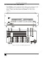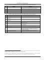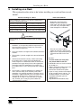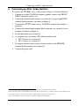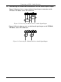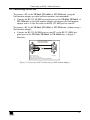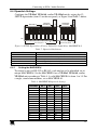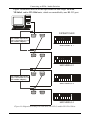
1
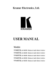
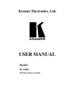
Kramer Electronics, Ltd.
USER MANUAL
Models:
VP-81xl, 8x1 XGA / Audio Switcher
VP-161xl, 16x1 XGA / Audio Switcher
VP-321xl, 32x1 XGA / Audio Switcher
Contents
Contents
1
2
2.1
3
4
4.1
4.2
4.3
5
6
6.1
6.2
6.3
6.4
Introduction
Getting Started
Quick Start
Overview
Your XGA / Audio Switcher
VP-81xl 8x1 XGA / Audio Switcher
VP-161xl 16x1 XGA / Audio Switcher
VP-321xl 32x1 XGA / Audio Switcher
Installing on a Rack
Connecting an XGA / Audio Switcher
Connecting the Balanced/Unbalanced Stereo Audio Input/Output
Controlling via RS-232
Controlling via RS-485
Dipswitch Settings
1
1
1
3
3
3
5
7
9
10
12
13
14
15
6.4.1
6.4.2
6.4.3
Setting the MACHINE #
Setting the MACHINE ADDRESS #
Example: Connecting a Set of Three Cascaded VP-81xl Units
15
17
19
6.5
7
7.1
Connecting the REMOTE Terminal Block Connector
Operating Your XGA / Audio Switcher
Using the Front Panel INPUT SELECTOR Buttons
20
22
22
7.1.1
7.1.2
7.1.3
7.1.3.1
7.1.3.2
7.1.3.3
Using the INPUT SELECTOR Buttons on a Single Unit
Using the INPUT SELECTOR Buttons on a Set of Units
Using the Audio-Follow-Video (AFV) / Breakaway Modes
Operating in Breakaway Mode
Toggling between Video and Audio Control in Breakaway Mode
Operating in the Audio-Follow-Video Mode
22
22
24
24
24
24
8
8.1
8.2
8.3
9
10
Flash Memory Upgrade
Downloading from the Internet
Connecting the PC to the RS-232 Port
Upgrading Firmware
Technical Specifications
Table of Hex Codes for Serial Communication
25
25
25
26
31
32
i
Contents
Figures
Figure 1: VP-81xl 8x1 XGA / Audio Switcher
Figure 2: VP-161xl 16x1 XGA / Audio Switcher
Figure 3: VP-321xl 32x1 XGA / Audio Switcher
Figure 4: Connecting the VP-81xl
Figure 5: Connecting the Balanced Stereo Audio Input/Output
Figure 6: Connecting the Unbalanced Stereo Audio Input/Output
Figure 7: Connecting a PC without using a Null-modem Adapter
Figure 8: Controlling via RS-485
Figure 9: SETUP Dipswitches (Factory Default for Stand-Alone MACHINE # 1)
Figure 10: Dipswitch Settings on 4 VP-81xl, VP-161xl, and/or VP-321xl Units
Figure 11: Three Looped VP-81xl Units Interconnected (Video Connections Shown)
Figure 12: Connecting a Remote Mechanical Switcher Unit to the VP-81xl
Figure 13: Connecting a Remote Unit to a Cascaded Set of Three VP-81xl Units
Figure 14: Operating a 22x1 XGA / Audio Switcher (Three Looped VP-81xl Units)
Figure 15: Splash Screen
Figure 16: Atmel – Flip Window
Figure 17: Open Configuration File Select Window
Figure 18: Atmel – Flip Window (RS-232 Communication)
Figure 19: RS-232 Window
Figure 20: Atmel – Flip Window (Connected)
Figure 21: Atmel – Flip Window (Operation Completed)
4
5
7
11
12
12
13
14
15
16
20
20
21
23
26
27
27
28
28
29
30
Tables
Table 1: Front Panel VP-81xl 8x1 XGA / Audio Switcher Features
Table 2: Rear Panel VP-81xl 8x1 XGA / Audio Switcher Features
Table 3: Front Panel VP-161xl 16x1 XGA / Audio Switcher Features
Table 4: Rear Panel VP-161xl 16x1 XGA / Audio Switcher Features
Table 5: Front Panel VP-321xl 32x1 XGA / Audio Switcher Features
Table 6: Rear Panel VP-321xl 32x1 XGA / Audio Switcher Features
Table 7: Dipswitch Definitions
Table 8: MACHINE # Dipswitch Settings
Table 9: MACHINE ADDRESS # Dipswitch Settings
Table 10: Technical Specifications of the VP-81xl/VP-161xl/VP-321xl
Table 11: VP-81xl/VP-161xl/VP-321xl Hex Codes
ii
4
4
6
6
8
8
15
15
18
31
32
KRAMER: SIMPLE CREATIVE TECHNOLOGY
Introduction
1
Introduction
Welcome to Kramer Electronics (since 1981): a world of unique, creative and
affordable solutions to the infinite range of problems that confront the video, audio
and presentation professional on a daily basis. In recent years, we have redesigned
and upgraded most of our line, making the best even better! Our 500-plus different
models now appear in 8 Groups1, which are clearly defined by function.
Congratulations on purchasing your Kramer XGA and balanced stereo audio
switcher, which is available in the following models: VP-81xl, VP-161xl, and
VP-321xl. The VP-81xl is an 8x1 XGA / Audio Switcher, the VP-161xl is a
16x1 XGA / Audio Switcher, and the VP-321xl is a 32x1 XGA / Audio Switcher.
The VP-81xl, VP-161xl, and VP-321xl are ideal for these typical applications:
Display systems requiring simple input selection (from 8 inputs to up to
218 inputs)
Remote monitoring of computer activity in schools and businesses
Rental/staging applications
Multimedia and presentation source selection
The package includes the following items:
XGA / Audio Switcher (VP-81xl, VP-161xl or VP-321xl)
Null-modem adapter, a power cord and an Infra-red remote control
transmitter (including the required battery and a separate user manual2)
This user manual2
2
Getting Started
We recommend that you:
Unpack the equipment carefully and save the original box and packaging
materials for possible future shipment
Review the contents of this user manual
Use Kramer high performance high resolution cables3
2.1 Quick Start
This quick start chart summarizes the basic setup and operation steps.
1 GROUP 1: Distribution Amplifiers; GROUP 2: Video and Audio Switchers, Matrix Switchers and Controllers; GROUP 3:
Video, Audio, VGA/XGA Processors; GROUP 4: Interfaces and Sync Processors; GROUP 5: Twisted Pair Interfaces;
GROUP 6: Accessories and Rack Adapters; GROUP 7: Scan Converters and Scalers; and GROUP 8: Cables and Connectors
2 Download up-to-date Kramer user manuals from the Internet at this URL: http://www.kramerelectronics.com
3 The complete list of Kramer cables is on our Web site at http://www.kramerelectronics.com
1
Getting Started
Audio connections
are not shown
1
2
2
Projector
Computer
Graphics
Source 8
1
RS-232
Computer
Graphics
Source 1
2
KRAMER: SIMPLE CREATIVE TECHNOLOGY
Overview
3
Overview
The VP-81xl, VP-161xl, and VP-321xl route any input to the output, using
15-pin HD female connectors for the VGA/XGA signals, and detachable
terminal block connectors for the balanced stereo audio.
In particular, the VP-81xl, VP-161xl, and VP-321xl include:
Very high video bandwidth, ensuring transparent VGA/XGA performance
Audio-follow-video (AFV) in which all operations relate to both the video
and the audio channels, or audio breakaway option, in which video and
audio channels switch independently
An ability to cascade up to seven units to increase the number of inputs
High standard directly coupled inputs and outputs
Compatibility with the Kramer VPM-2 XGA Line Driver wall plate
Control from the front panel, or via RS-232/RS-485 serial commands
transmitted by a touch screen system, PC, or other serial control device, as
well as via an infra-red remote controller, or via remote contact-closure
switches
To achieve the best performance:
Connect only good quality connection cables, thus avoiding interference,
deterioration in signal quality due to poor matching, and elevated noise
levels (often associated with low quality cables)
Avoid interference from neighboring electrical appliances that may
adversely influence signal quality and position your
VP-81xl/VP-161xl/VP-321xl away from moisture, excessive sunlight and
dust
4
Your XGA / Audio Switcher
This section includes a description of the:
VP-81xl, 8x1 XGA / Audio Switcher (see section 4.1)
VP-161xl, 16x1 XGA / Audio Switcher (see section 4.2)
VP-321xl, 32x1 XGA / Audio Switcher (see section 4.3)
4.1 VP-81xl 8x1 XGA / Audio Switcher
The VP-81xl is an 8x1 switcher for VGA / XGA signals and balanced audio
stereo signals that lets you route one of up to 8 inputs to one output.
Figure 1, Table 1 and Table 2 define the VP-81xl 8x1 XGA / Audio Switcher:
3
Your XGA / Audio Switcher
REMOTE
8 7 6
AUDIO
5 4 3
2 1 G
OUTPUT
+ LG - + RG -
OUTPUT
8
ID BIT
INPUT 8
INPUT 7
INPUT 6
INPUT 5
INPUT 4
INPUT 3
INPUT 2
INPUT 1
+ LG - + RG -
+ LG - + RG -
+ LG - + RG -
+ LG - + RG -
+ LG - + RG -
+ LG - + RG -
+ LG - + RG -
+ LG - + RG -
7
6
ID BIT
5
4
ID BIT
3
G + -
RS-232 IN
2
ID BIT
RS-232 OUT
RS-485
1
FUSE
Figure 1: VP-81xl 8x1 XGA / Audio Switcher
Table 1: Front Panel VP-81xl 8x1 XGA / Audio Switcher Features
1
#
IR Receiver
Feature
2
3
POWER Switch
INPUT SELECTOR Buttons
Function
The red LED is illuminated when receiving signals from the
Kramer Infra-red remote control transmitter
Illuminated switch supplying power to the unit
Select the input to switch to the output (from 1 to 8)
4
5
AUDIO Button
VIDEO Button
When illuminated1 actions relate to audio
When illuminated1 actions relate to video
Table 2: Rear Panel VP-81xl 8x1 XGA / Audio Switcher Features
#
6
7
8
9
10
11
Feature
REMOTE Terminal Block
Connectors
AUDIO OUTPUT Terminal Block
Connector
AUDIO INPUTS Terminal Block
Connectors
RS-232 IN DB 9F Port
RS-232 OUT DB 9M Port
12
13
14
RS-485 Detachable Terminal
Block Port
Power Connector with FUSE
SETUP Dipswitches
ID BIT Switch
15
16
INPUT HD15F Connectors
OUTPUT HD15F Connector
Function
Connect to the remote contact-closure switches
Connect to the balanced audio acceptor
Connect to the balanced audio sources (from 1 to 8)
Connects to the PC or RS-232 remote controller
Connects to the RS-232 IN DB 9F port of the next unit in the
daisy-chain
Pin # 1 is for Ground connection, and Pins # 2 and # 3 are for
RS-485
AC connector enabling power supply to the unit
Dipswitches for setup of the unit
Selects the ID BIT when switched ON (when outputting the input
signal from a notebook connected to an external VGA monitor)2
Connect to the VGA/XGA sources (from 1 to 8)
Connects to the VGA/XGA acceptor
1 If the AUDIO and VIDEO buttons both illuminate, the unit operates in the audio-follow-video mode. If only one button
illuminates (AUDIO or VIDEO), the unit operates in the breakaway mode
2 Sometimes notebook computers refuse to output a VGA signal to an external VGA monitor if they do not detect the ID BIT
as ON. Set the ID BIT to ON using this button so that the notebook will output to an external VGA monitor
4
KRAMER: SIMPLE CREATIVE TECHNOLOGY
Your XGA / Audio Switcher
4.2 VP-161xl 16x1 XGA / Audio Switcher
The VP-161xl is a 16x1 switcher for VGA / XGA signals and balanced audio
stereo signals that lets you route one of up to 16 inputs to one output.
Figure 2, Table 3 and Table 4 define the VP-161xl 16x1 XGA / Audio
Switcher:
REMOTE
AUDIO
16 15 14
13 12 11
10 9 G
8 7 6
5 4 3
2 1 G
OUTPUT
OUTPUT
+ LG - + RG -
INPUT 16
INPUT 1
INPUT 16
INPUT 15
INPUT 14
INPUT 13
INPUT 12
INPUT 11
INPUT 10
INPUT 9
+ LG - + RG -
+ LG - + RG -
+ LG - + RG -
+ LG - + RG -
+ LG - + RG -
+ LG - + RG -
+ LG - + RG -
+ LG - + RG -
INPUT 1
INPUT 2
INPUT 3
INPUT 4
INPUT 5
INPUT 6
INPUT 7
INPUT 8
+ LG - + RG -
+ LG - + RG -
+ LG - + RG -
+ LG - + RG -
+ LG - + RG -
+ LG - + RG -
+ LG - + RG -
+ LG - + RG -
ID BIT
16
15
INPUT 15
INPUT 14
ID BIT
INPUT 2
INPUT 3
1
2
ID BIT
14
13
INPUT 13
INPUT 12
ID BIT
INPUT 4
INPUT 5
3
4
ID BIT
12
11
INPUT 11
INPUT 10
ID BIT
INPUT 6
INPUT 7
5
6
G + -
RS-232 IN
ID BIT
10
9
INPUT 9
ID BIT
INPUT 8
7
8
RS-232 OUT
RS-485
SETUP
Figure 2: VP-161xl 16x1 XGA / Audio Switcher
5
Your XGA / Audio Switcher
Table 3: Front Panel VP-161xl 16x1 XGA / Audio Switcher Features
1
#
IR Receiver
Feature
2
3
POWER Switch
INPUT SELECTOR Buttons
Function
The red LED is illuminated when receiving signals from
the Kramer Infra-red remote control transmitter
Illuminated switch supplying power to the unit
Select the input to switch to the output (from 1 to 16)
4
5
AUDIO Button
VIDEO Button
When illuminated actions relate to audio
1
When illuminated actions relate to video
1
Table 4: Rear Panel VP-161xl 16x1 XGA / Audio Switcher Features
#
9
10
Feature
REMOTE Terminal Block Connectors
AUDIO OUTPUT Terminal Block
Connector
AUDIO INPUTS Terminal Block
Connectors
RS-232 IN DB 9F Port
RS-232 OUT DB 9M Port
11
RS-485 Detachable Terminal Block Port
12
13
14
15
Power Connector with FUSE
SETUP Dipswitches
INPUT HD15F Connectors
ID BIT Switch
16
OUTPUT HD15F Connector
6
7
8
Function
Connect to the remote contact-closure switches
Connect to the balanced audio acceptor
Connect to the balanced audio sources (from 1 to 16)
Connects to the PC or RS-232 remote controller
Connects to the RS-232 IN DB 9F port of the next unit
in the daisy-chain
Pin # 1 is for Ground connection, and Pins # 2 and # 3
are for RS-485
AC connector enabling power supply to the unit
Dipswitches for setup of the unit
Connect to the VGA/XGA sources (from 1 to 16)
Selects the ID BIT when switched ON (when outputting
the input signal from a notebook connected to an
external VGA monitor)2
Connects to the VGA/XGA acceptor
1 If the AUDIO and VIDEO buttons both illuminate, the unit operates in the audio-follow-video mode. If only one button
illuminates (AUDIO or VIDEO), the unit operates in the breakaway mode
2 Sometimes notebook computers refuse to output a VGA signal to an external VGA monitor if they do not detect the ID BIT
as ON. Set the ID BIT to ON using this button so that the notebook will output to an external VGA monitor
6
KRAMER: SIMPLE CREATIVE TECHNOLOGY
Your XGA / Audio Switcher
4.3 VP-321xl 32x1 XGA / Audio Switcher
The VP-321xl is a 32x1 switcher for VGA / XGA signals and balanced audio
stereo signals that lets you route one of up to 32 inputs to one output.
Figure 3, Table 5 and Table 6 define the VP-321xl 32x1 XGA / Audio
Switcher:
AUDIO
REMOTE
32 31 30
29 28 27
26 25 G
OUTPUT
+ LG - + RG -
INPUT 32
INPUT 31
INPUT 30
INPUT 29
INPUT 28
INPUT 27
INPUT 26
INPUT 25
+ LG - + RG -
+ LG - + RG -
+ LG - + RG -
+ LG - + RG -
+ LG - + RG -
+ LG - + RG -
+ LG - + RG -
+ LG - + RG -
INPUT 17
INPUT 18
INPUT 19
INPUT 20
INPUT 21
INPUT 22
INPUT 23
INPUT 24
+ LG - + RG -
+ LG - + RG -
+ LG - + RG -
+ LG - + RG -
+ LG - + RG -
+ LG - + RG -
+ LG - + RG -
24 23 22
21 20 19
18 17 G
+ LG - + RG INPUT 16
INPUT 15
INPUT 14
INPUT 13
INPUT 12
INPUT 11
INPUT 10
INPUT 9
16 15 14
13 12 11
10 9 G
+ LG - + RG -
+ LG - + RG -
+ LG - + RG -
+ LG - + RG -
+ LG - + RG -
+ LG - + RG -
+ LG - + RG -
+ LG - + RG -
INPUT 1
INPUT 2
INPUT 3
INPUT 4
INPUT 5
INPUT 6
INPUT 7
INPUT 8
8 7 6
5 4 3
2 1 G
+ LG - + RG -
+ LG - + RG -
+ LG - + RG -
+ LG - + RG -
+ LG - + RG -
+ LG - + RG -
+ LG - + RG -
+ LG - + RG -
OUTPUT
G
RS-232 IN
INPUT 32
ID BIT
32
31
INPUT 31
INPUT 30
ID BIT
30
29
INPUT 29
INPUT 28
ID BIT
28
27
INPUT 27
INPUT 26
26
INPUT 25
INPUT 17
ID BIT
17
18
INPUT 18
INPUT 19
ID BIT
19
20
INPUT 20
INPUT 21
ID BIT
21
22
INPUT 22
INPUT 23
23
INPUT 24
INPUT 16
ID BIT
16
15
INPUT 15
INPUT 14
ID BIT
14
13
INPUT 13
INPUT 12
ID BIT
12
11
INPUT 11
INPUT 10
10
INPUT 9
INPUT 1
ID BIT
INPUT 3
ID BIT
INPUT 5
ID BIT
INPUT 6
INPUT 7
7
INPUT 8
1
2
INPUT 2
3
4
INPUT 4
5
6
RS-232 OUT
+ -
RS-485
SETUP
Figure 3: VP-321xl 32x1 XGA / Audio Switcher
7
Your XGA / Audio Switcher
Table 5: Front Panel VP-321xl 32x1 XGA / Audio Switcher Features
1
#
IR Receiver
Feature
2
3
POWER Switch
INPUT SELECTOR Buttons
Function
The red LED is illuminated when receiving signals from
the Kramer Infra-red remote control transmitter
Illuminated switch supplying power to the unit
Select the input to switch to the output (from 1 to 32)
4
5
AUDIO Button
VIDEO Button
When illuminated actions relate to audio
1
When illuminated actions relate to video
1
Table 6: Rear Panel VP-321xl 32x1 XGA / Audio Switcher Features
#
9
10
Feature
REMOTE Terminal Block Connectors
AUDIO OUTPUT Terminal Block
Connector
AUDIO INPUTS Terminal Block
Connectors
RS-232 IN DB 9F Port
RS-232 OUT DB 9M Port
11
RS-485 Detachable Terminal Block Port
12
13
14
Power Connector with FUSE
SETUP Dipswitches
ID BIT Switch
15
16
INPUT HD15F Connectors
OUTPUT HD15F Connector
6
7
8
Function
Connect to the remote contact-closure switches
Connect to the balanced audio acceptor
Connect to the balanced audio sources (from 1 to 32)
Connects to the PC or RS-232 remote controller
Connects to the RS-232 IN DB 9F port of the next unit
in the daisy-chain
Pin # 1 is for Ground connection, and Pins # 2 and # 3
are for RS-485
AC connector enabling power supply to the unit
Dipswitches for setup of the unit
Selects the ID BIT when switched ON (when outputting
the input signal from a notebook connected to an
external VGA monitor)2
Connect to the VGA/XGA sources (from 1 to 32)
Connects to the VGA/XGA acceptor
1 If the AUDIO and VIDEO buttons both illuminate, the unit operates in the audio-follow-video mode. If only one button
illuminates (AUDIO or VIDEO), the unit operates in the breakaway mode
2 Sometimes notebook computers refuse to output a VGA signal to an external VGA monitor if they do not detect the ID BIT
as ON. Set the ID BIT to ON using this button so that the notebook will output to an external VGA monitor
8
KRAMER: SIMPLE CREATIVE TECHNOLOGY
Installing on a Rack
5
Installing on a Rack
This section describes what to do before installing on a rack and how to rack
mount1.
Before Installing on a Rack
Before installing on a rack, be sure that the environment is
within the recommended range:
How to Rack Mount
To rack-mount a machine:
1
Attach both ear brackets to the
machine. To do so, remove the
screws from each side of the machine
(3 on each side), and replace those
screws through the ear brackets.
2
Place the ears of the machine
against the rack rails, and insert the
proper screws (not provided) through
each of the four holes in the rack
ears.
Operating temperature range +5 to +45 Deg. Centigrade
Operating humidity range
5 to 65% RHL, non-condensing
Storage temperature range
-20 to +70 Deg. Centigrade
Storage humidity range
5 to 95% RHL, non-condensing
CAUTION!!
When installing on a 19" rack, avoid hazards by taking
care that:
1 It is located within the recommended environmental
conditions, as the operating ambient temperature of a
closed or multi unit rack assembly may exceed the
room ambient temperature.
2 Once rack mounted, enough air will still flow around the
machine.
3 The machine is placed straight in the correct horizontal
position.
4 You do not overload the circuit(s). When connecting
the machine to the supply circuit, overloading the
circuits might have a detrimental effect on overcurrent
protection and supply wiring. Refer to the appropriate
nameplate ratings for information. For example, for
fuse replacement, see the value printed on the product
label.
5 The machine is earthed (grounded) in a reliable way
and is connected only to an electricity socket with
grounding. Pay particular attention to situations where
electricity is supplied indirectly (when the power cord is
not plugged directly into the socket in the wall), for
example, when using an extension cable or a power
strip, and that you use only the power cord that is
supplied with the machine.
Note that:
In some models, the front panel
may feature built-in rack ears
Detachable rack ears can be removed
for desktop use
Always mount the machine in the rack
before you attach any cables or
connect the machine to the power
If you are using a Kramer rack adapter
kit (for a machine that is not 19"), see
the Rack Adapters user manual for
installation instructions (you can
download it at:
http://www.kramerelectronics.com)
1 This section applies to VP-81xl, VP-161xl and VP-321xl
9
Connecting an XGA / Audio Switcher
6
Connecting an XGA / Audio Switcher
To connect the VP-81xl1, unit, as illustrated in Figure 4, do the following2:
1. Connect up to eight VGA/XGA computer graphics sources to the HD15F
INPUT connectors (from 1 to 8).
2. Connect the balanced audio sources (see section 6.1) to up to eight INPUT
terminal block connectors (not shown in Figure 4)
3. Connect the OUTPUT connector to a VGA/XGA acceptor (for example, a
projector).
4. Connect the balanced audio terminal block connector (see section 6.1) to an
acceptor (not shown in Figure 4).
5. Set the dipswitches (see section 6.4)
6. As an option you can connect a PC and/or controller to the:
RS-232 port (see section 6.2)
RS-485 port (see section 6.3)
7. If required, connect remote contact-closure switches to the REMOTE
terminal block connector (see section 6.5)
8. Connect the power cord3.
1 The same connecting principles apply to the VP-161xl (16 inputs) and the VP-321xl (32 inputs)
2 Be sure that the power is switched OFF on each device before connecting it to your unit(s). After connecting all the devices
to your unit(s), switch on the power of the unit(s), and then switch on the power of each device
3 We recommend that you use only the power cord that is supplied with this machine
10
KRAMER: SIMPLE CREATIVE TECHNOLOGY
Connecting an XGA / Audio Switcher
Audio connections
are not shown
Projector
RS-232
Computer Graphics
Source 8
Computer Graphics
Source 1
Figure 4: Connecting the VP-81xl
11
Connecting an XGA / Audio Switcher
6.1 Connecting the Balanced/Unbalanced Stereo Audio Input/Output
Figure 5 illustrates how to wire a balanced input/output connection on the
VP-81xl, VP-161xl, and/or VP-321xl unit:
Figure 5: Connecting the Balanced Stereo Audio Input/Output
Figure 6 illustrates how to wire an unbalanced input/output on the VP-81xl,
VP-161xl, and/or VP-321xl unit:
Figure 6: Connecting the Unbalanced Stereo Audio Input/Output
12
KRAMER: SIMPLE CREATIVE TECHNOLOGY
Connecting an XGA / Audio Switcher
6.2 Controlling via RS-232
To connect a PC to the VP-81xl, VP-161xl, or VP-321xl unit, using the
Null-modem adapter provided with the machine (recommended):
Connect the RS-232 IN DB9 rear panel port on the VP-81xl, VP-161xl, or
VP-321xl unit to the Null-modem adapter and connect the Null-modem
adapter with a 9-wire flat cable to the RS-232 DB9 port on your PC
To connect a PC to the VP-81xl, VP-161xl, or VP-321xl unit, without using a
Null-modem adapter:
Connect the RS-232 IN DB9 port on your PC to the RS-232 DB9 rear
panel port on the VP-81xl, VP-161xl, or VP-321xl unit, as Figure 7
illustrates
PIN 5 Connected to PIN 5 (Ground)
PIN 3 Connected to PIN 2
PIN 2 Connected to PIN 3
Female DB9 (From PC)
Male DB9
PIN 4 Connected to PIN 6
PINS 8, 7, 1 Connected together
If a Shielded cable is used, connect the shield to PIN 5
Figure 7: Connecting a PC without using a Null-modem Adapter
13
Connecting an XGA / Audio Switcher
6.3 Controlling via RS-485
You can control a VP-81xl, VP-161xl, or VP-321xl unit(s) via any RS-485
remote controller or a PC (equipped with an RS-485 interface).
To connect an RS-485 remote controller to two VP-81xl/VP-161xl/VP-321xl
units (see Figure 8):
1. Connect the RS-485 port on the RS-485 remote controller to the RS-485 ports
on the VP-81xl/VP-161xl/VP-321xl units, as follows:
Connect the “A” (+) PIN on the RS-485 remote controller to the “+” (A)
PINs on the RS-485 ports of the VP-81xl/VP-161xl/VP-321xl units
Connect the “B” (-) PIN on the RS-485 remote controller to the “B” (-)
PINs on the RS-485 ports of the VP-81xl/VP-161xl/VP-321xl units
If shielded twisted pair cable is used, the shield may be connected to
the “G” (Ground) PIN on one of the units (for example, on the
RS-485 remote controller)
2. Set the SETUP dipswitches on the VP-81xl/VP-161xl/VP-321xl units as
follows:
Set the first VP-81xl/VP-161xl/VP-321xl unit to MACHINE # 11
Set the second VP-81xl/VP-161xl/VP-321xl unit to MACHINE # 21
and set DIP 12 to ON, terminating the RS-485 line2
REMOTE
CONTROLLER
G
TERMINATE
RS-485
CONNECTION
+ -
RS-485
DIPSWITCHES
G
SWITCHER # 1
+ -
RS-485
MACHINE # 1
G
SWITCHER # 2
+ -
TERMINATE
RS-485
CONNECTION
RS-485
MACHINE # 2
Figure 8: Controlling via RS-485
1 See Table 8
2 The RS-485 line must also be terminated at the remote controller. Refer to the remote controller’s user manual for details of
how to terminate the RS-485 line on the remote controller
14
KRAMER: SIMPLE CREATIVE TECHNOLOGY
Connecting an XGA / Audio Switcher
6.4 Dipswitch Settings
FIRMWARE
UPGRADE
RS-485
Termination
MACHINE
ADDRESS #
MACHINE #
Last in
daisy-chain
Configure the VP-81xl, VP-161xl, and/or VP-321xl unit by setting the 12
SETUP dipswitches (item 13 on the rear panel), as Figure 9 and Table 7 define:
ON
1
2
3
4
5
6
8
First Set (DIP 1 - 8)
1
2
3
4
Second Set (DIP 9 - 12)
Figure 9: SETUP Dipswitches (Factory Default for Stand-Alone MACHINE # 1)
Table 7: Dipswitch Definitions
DIP
1-4
5-7
8
9-11 (marked 1-3 on second set)
12 (marked 4 on second set)
6.4.1
Function:
Set the MACHINE # (see section 6.4.1)
MACHINE ADDRESS # in daisy chain connection (see section 6.4.2)
Last in daisy chain
Firmware Upgrade (see section 8)
RS-485 Termination (see section 6.3)
Setting the MACHINE #
To control a unit via RS-232 or RS-485, each unit has to be identified via its
unique MACHINE #. Set the MACHINE # on a VP-81xl, VP-161xl, and/or
VP-321xl unit according to Table 8. A valid MACHINE # is from 1 to 15. For
a single, stand-alone machine, set as MACHINE # 1.
Table 8: MACHINE # Dipswitch Settings
MACHINE #
1
DIP 1
ON
DIP 2
OFF
DIP 3
OFF
DIP 4
OFF
2
OFF
ON
OFF
OFF
3
ON
ON
OFF
OFF
4
OFF
OFF
ON
OFF
5
6
7
8
9
10
11
12
13
14
15
ON
OFF
ON
OFF
ON
OFF
ON
OFF
ON
OFF
ON
OFF
ON
ON
OFF
OFF
ON
ON
OFF
OFF
ON
ON
ON
ON
ON
OFF
OFF
OFF
OFF
ON
ON
ON
ON
OFF
OFF
OFF
ON
ON
ON
ON
ON
ON
ON
ON
15
Connecting an XGA / Audio Switcher
Figure 10 illustrates how to set the dipswitches on four single VP-81xl,
VP-161xl, and/or VP-321xl units, which are controlled by one RS-232 port:
RS-232 OUT
Null-modem connection
(cross-connection or use
Null-modem adapter)
DIPSWITCHES
RS-232 IN
MACHINE # 1
RS-232 OUT
RS-232 IN
MACHINE # 2
RS-232 OUT
Null-modem connection
(cross-connection or use
Null-modem adapter)
RS-232 IN
MACHINE # 3
RS-232 OUT
RS-232 IN
MACHINE # 4
Figure 10: Dipswitch Settings on 4 VP-81xl, VP-161xl, and/or VP-321xl Units
16
KRAMER: SIMPLE CREATIVE TECHNOLOGY
Connecting an XGA / Audio Switcher
6.4.2
Setting the MACHINE ADDRESS #
For certain applications, you may need more than 8 inputs1. Cascading the
inputs of VP-81xl/VP-161xl/VP-321xl units enables you to expand the
number of inputs by looping up to seven units to form a combined XGA /
Audio Switcher with up to 218 inputs. Be aware that:
Cascading VP-81xl/VP-161xl/VP-321xl units can cause XGA signal
quality degradation
Choosing the quantity of VP-81xl/VP-161xl/VP-321xl units to cascade
depends on your particular XGA signal quality requirements
The technical specifications contained in Table 10 are guaranteed for
stand-alone units only
To cascade up to seven identical2 units, that is, seven VP-81xl units, or seven
VP-161xl units, or seven VP-321xl units:
Set the same MACHINE # on each unit, according to Table 8
Set the MACHINE ADDRESS # and the eighth dipswitch (last in
daisy-chain) on each unit that is included in a set, according to Table 9
1 For example, if you want to connect 50 VGA/XGA audio sources and then be able to switch any one of them at any time
2 Only the same types of units (for example, seven VP-161xl units) can be cascaded – you cannot mix the various types (a
cascade cannot include say, four VP-81xl units, and three VP-161xl units)
17
Connecting an XGA / Audio Switcher
Table 9: MACHINE ADDRESS # Dipswitch Settings
INPUTS AVAILABLE ON THE:
VP-81xl
VP-161xl
VP-321xl
DIP 5
DIP 6
DIP 7
DIP 8
8
16
32
1
OFF
OFF
OFF
OFF
15
31
63
1
ON
OFF
OFF
OFF
2
OFF
ON
OFF
ON
1
ON
OFF
OFF
OFF
2
OFF
ON
OFF
OFF
3
ON
ON
OFF
ON
1
ON
OFF
OFF
OFF
2
OFF
ON
OFF
OFF
3
ON
ON
OFF
OFF
22
29
36
43
50
18
MACHINE
ADDRESS #
46
61
76
91
106
94
125
156
187
218
4
OFF
OFF
ON
ON
1
ON
OFF
OFF
OFF
2
OFF
ON
OFF
OFF
3
ON
ON
OFF
OFF
4
OFF
OFF
ON
OFF
5
ON
OFF
ON
ON
1
ON
OFF
OFF
OFF
2
OFF
ON
OFF
OFF
3
ON
ON
OFF
OFF
4
OFF
OFF
ON
OFF
5
ON
OFF
ON
OFF
6
OFF
ON
ON
ON
OFF
1
ON
OFF
OFF
2
OFF
ON
OFF
OFF
3
ON
ON
OFF
OFF
4
OFF
OFF
ON
OFF
5
ON
OFF
ON
OFF
6
OFF
ON
ON
OFF
7
ON
ON
ON
ON
KRAMER: SIMPLE CREATIVE TECHNOLOGY
Connecting an XGA / Audio Switcher
6.4.3
Example: Connecting a Set of Three Cascaded VP-81xl Units
In this example, 22 inputs are connected using three looped VP-81xl units,
with control via a single RS-232 port. You can route any one of the 22 inputs
to the XGA / Audio acceptor, as Figure 11 illustrates1.
To connect a set of three looped VP-81xl units with 22 inputs, do the following:
1. On the first VP-81xl unit, connect the:
XGA HD15F OUTPUT connector to the XGA INPUT 1 HD15F
connector on the second VP-81xl unit
AUDIO OUTPUT terminal block connector to the Audio INPUT 1
terminal block connector on the second VP-81xl unit
2. On the second VP-81xl unit, connect the:
XGA HD15F OUTPUT connector to the XGA INPUT 1 HD15F
connector on the third VP-81xl unit
AUDIO OUTPUT terminal block connector to the Audio INPUT 1
terminal block connector on the third VP-81xl unit
3. On the third VP-81xl unit, connect the:
XGA HD15F OUTPUT connector and the AUDIO OUTPUT
terminal block connector to the XGA/Audio acceptor
4. Connect the XGA HD15F INPUT connectors 1 to 8 and the Audio INPUT
terminal block connectors 1 to 8 on the first looped VP-81xl unit to the
XGA/Audio sources 1 to 8.
5. Connect the XGA HD15F INPUT connectors 2 to 8 and the Audio INPUT
terminal block connectors 2 to 8 on the:
Second looped VP-81xl unit to the XGA/Audio sources 9 to 15
Third looped VP-81xl unit to the XGA/Audio sources 16 to 22
6. Set the dipswitches as per Table 8 and Table 9. In particular, set:
Each VP-81xl unit to MACHINE # 1
The first VP-81xl unit to MACHINE ADDRESS # 1, the second
VP-81xl unit to MACHINE ADDRESS # 2, and the third VP-81xl
unit to MACHINE ADDRESS # 3
DIP 8 on the third (and Last in Daisy-chain) VP-81xl unit to ON
7. Control via RS-485 (see Figure 8) or via RS-232 (see Figure 10).
1 Only the video connections are shown. Audio should be connected in a similar manner
19
Connecting an XGA / Audio Switcher
REMOTE
8 7 6
AUDIO
5 4 3
2 1 G
OUTPUT
+ LG - + RG -
OUTPUT
ID BIT
INPUT 7
INPUT 6
INPUT 5
INPUT 4
INPUT 3
INPUT 2
INPUT 1
+ LG - + RG -
+ LG - + RG -
+ LG - + RG -
+ LG - + RG -
+ LG - + RG -
+ LG - + RG -
+ LG - + RG -
+ LG - + RG -
7
6
ID BIT
5
4
ID BIT
3
2
ID BIT
1
…
8
INPUT 8
REMOTE
8 7 6
AUDIO
5 4 3
2 1 G
OUTPUT
+ LG - + RG -
OUTPUT
ID BIT
INPUT 7
INPUT 6
INPUT 5
INPUT 4
INPUT 3
INPUT 2
INPUT 1
+ LG - + RG -
+ LG - + RG -
+ LG - + RG -
+ LG - + RG -
+ LG - + RG -
+ LG - + RG -
+ LG - + RG -
7
6
ID BIT
5
4
ID BIT
3
2
ID BIT
REMOTE
8 7 6
AUDIO
5 4 3
2 1 G
OUTPUT
OUTPUT
+ LG - + RG -
8
ID BIT
7
INPUT 8
INPUT 7
INPUT 6
INPUT 5
INPUT 4
INPUT 3
INPUT 2
INPUT 1
+ LG - + RG -
+ LG - + RG -
+ LG - + RG -
+ LG - + RG -
+ LG - + RG -
+ LG - + RG -
+ LG - + RG -
+ LG - + RG -
6
ID BIT
5
4
ID BIT
3
ID BIT
9
MACHINE # 1
MACHINE ADDRESS # 2
15
1
…
XGA/AUDIO
ACCEPTOR
2
MACHINE # 1
MACHINE ADDRESS # 1
8
1
…
8
INPUT 8
+ LG - + RG -
1
16
MACHINE # 1
MACHINE ADDRESS # 3
Last in Daisy-chain = ON
22
Figure 11: Three Looped VP-81xl Units Interconnected (Video Connections Shown)
6.5 Connecting the REMOTE Terminal Block1 Connector
Connect remote contact-closure switches to the REMOTE terminal block
connector, for example to a single XGA/Audio switcher such as the VP-81xl,
as Figure 12 describes. A remote unit can consist of a mechanical switcher2
with a common wire for ground3.
Figure 12: Connecting a Remote Mechanical Switcher Unit to the VP-81xl
1 The REMOTE terminal block connector has 8 pins (plus the G pin) on the VP-81xl, 16 pins on the VP-161xl, and 32 pins
on the VP-321xl
2 The remote unit can have up to 8 buttons for the VP-81xl, corresponding to the front panel INPUT SELECTOR buttons.
Similarly, 16 buttons for the VP-161xl, and 32 buttons for the VP-321xl
3 Providing control over a distance up to hundreds of meters
20
KRAMER: SIMPLE CREATIVE TECHNOLOGY
Connecting an XGA / Audio Switcher
You can also connect remote contact-closure switches to the REMOTE terminal
block connectors (according to Table 9). The example in Figure 13 illustrates
how to connect remote contact-closure switches to the REMOTE terminal block
connectors on a set of three looped VP-81xl units:
............
VP-81xl Unit # 1
1
2
............
7
8
14
15
............
VP-81xl Unit # 2
9
............
............
VP-81xl Unit # 3
16
............
21
22
G
Figure 13: Connecting a Remote Unit to a Cascaded Set of Three VP-81xl Units
21
Operating Your XGA / Audio Switcher
7
Operating Your XGA / Audio Switcher
You can operate your XGA / Audio Switcher, whether it consists of a single
VP-81xl/VP-161xl/VP-321xl unit, or of a set of VP-81xl/VP-161xl/VP-321xl
units, via the following:
The front panel INPUT SELECTOR buttons, as section 7.1 describes
Remotely, by RS-485 or RS-232 serial commands transmitted by a touch
screen system, PC, or other serial controller
Remote contact-closure switches (see section 6.5)
Remotely, from the Kramer RC-IR1 Infra-Red Remote Control
Transmitter1 (refer to the RC-IR1 user manual2)
Powering up VP-81xl/VP-161xl/VP-321xl unit, recalls the previous settings
(that is, the state of the unit when it was powered down) from the non-volatile
memory.
7.1 Using the Front Panel INPUT SELECTOR Buttons
To use the INPUT SELECTOR buttons on a:
Single VP-81xl/VP-161xl/VP-321xl unit, see section 7.1.1
Set of looped VP-81xl/VP-161xl/VP-321xl units, see section 7.1.2
7.1.1
Using the INPUT SELECTOR Buttons on a Single Unit
To operate the INPUT SELECTOR buttons on a single
VP-81xl/VP-161xl/VP-321xl unit:
Press one of the 8 front panel INPUT SELECTOR buttons on the front
panel of a VP-81xl/VP-161xl/VP-321xl unit
The INPUT SELECTOR button illuminates and routes that input to the
output
7.1.2
Using the INPUT SELECTOR Buttons on a Set of Units
When operating a set of up to seven looped VP-81xl/VP-161xl/VP-321xl
units, not all the INPUT SELECTOR buttons on the front panels of the
combined VP-81xl/VP-161xl/VP-321xl units are active.
For example, as Figure 14 illustrates, with a combination of three VP-81xl
units, you cannot use all the 8 INPUT SELECTOR buttons on each looped
VP-81xl unit.
1 Previously known as the IR-1/IR-1-01
2 Download up-to-date Kramer user manuals from our Web site at: http://www.kramerelectronics.com
22
KRAMER: SIMPLE CREATIVE TECHNOLOGY
Operating Your XGA / Audio Switcher
INPUT SELECTOR buttons 1 on the second and third units are inactive. You
cannot connect INPUT 1 on the second and third units to an independent
source because INPUT 1 on the second unit is connected to the OUTPUT on
the first unit and INPUT 1 on the third unit is connected to the OUTPUT on
the second unit.
INPUT SELECTOR buttons marked 1 to 8 on the first looped VP-81xl unit
operate INPUTS 1 to 8, respectively. INPUT SELECTOR buttons marked 2
to 8 on the second looped VP-81xl unit operate INPUTS 9 to 15, respectively.
INPUT SELECTOR buttons marked 2 to 8 on the third looped VP-81xl unit
operate INPUTS 16 to 22, respectively.
Unit # 1
Unit # 2
Unit # 3
Figure 14: Operating a 22x1 XGA / Audio Switcher (Three Looped VP-81xl Units)
To operate the INPUT SELECTOR buttons on a set of three VP-81xl units:
Press an active INPUT SELECTOR button on the front panel of one of
the looped VP-81xl units
The active INPUT SELECTOR button illuminates and switches that input
to the output. For example, as the example in Figure 14 illustrates,
pressing INPUT SELECTOR button # 3 on VP-81xl unit # 2
automatically switches source # 10 to the output
23
Operating Your XGA / Audio Switcher
7.1.3
Using the Audio-Follow-Video (AFV) / Breakaway Modes
By default, a VP-81xl/VP-161xl/VP-321xl unit, or set of units, switches in
true audio-follow-video mode in which all operations relate to both the video
and audio. Both the VIDEO and the AUDIO buttons illuminate in this mode.
7.1.3.1
Operating in Breakaway Mode
To operate in breakaway mode, in which video and audio channels switch
independently:
Press either the VIDEO button or the AUDIO button (only one button, the
VIDEO button or the AUDIO button illuminate at this time)
If the VIDEO button illuminates, the switching relates just to video (and
the audio remains unchanged)
If the AUDIO button illuminates, the switching relates only to audio (and
the video remains unchanged)
7.1.3.2
Toggling between Video and Audio Control in Breakaway Mode
To toggle between video and audio control, press the corresponding button:
For audio, press the AUDIO button
This selects audio, illuminating the AUDIO button (the VIDEO button
will not illuminate), or
For video, press the VIDEO button
This selects video, illuminating the VIDEO button (the AUDIO button
will not illuminate)
7.1.3.3
Operating in the Audio-Follow-Video Mode
To operate in audio-follow-video (AFV) mode1, press both the VIDEO and
the AUDIO buttons simultaneously.
1 In which the AUDIO and VIDEO buttons both illuminate. If only one button illuminates (AUDIO or VIDEO), the unit
operates in the breakaway mode
24
KRAMER: SIMPLE CREATIVE TECHNOLOGY
Flash Memory Upgrade
8
Flash Memory Upgrade
The VP-81xl/VP-161xl/VP-321xl firmware is located in FLASH memory,
which lets you upgrade to the latest Kramer firmware version in minutes! The
process involves:
Downloading from the Internet (see section 8.1)
Connecting the PC to the RS-232 port (see section 8.2)
Upgrading firmware (see section 8.3)
8.1 Downloading from the Internet
You can download the up-to-date file from the Internet. To do so:
1. Go to our Web site at http://www.kramerelectronics.com and download the
appropriate file1 from the Technical Support section.
The same file is applicable to all models (VP-81xl, VP-161xl and/or
VP-321xl). The program automatically recognizes the size of the switcher.
2. Extract the downloaded file to a folder (for example, C:\Program Files\Kramer
Flash).
8.2 Connecting the PC to the RS-232 Port
Before installing the latest Kramer firmware version on a
VP-81xl/VP-161xl/VP-321xl unit, do the following:
1. Connect the RS-232 DB9 rear panel port on the VP-81xl/VP-161xl/VP-321xl
unit to the Null-modem adapter and connect the Null-modem adapter with a 9
wire flat cable to the RS-232 DB9 COM port on your PC (see section 6.2).
It is recommended that you use COM port2 2. However, if your computer
has only one COM port, open the configuration file3 (located at C:\Program
Files\Kramer Flash\) in Notepad, and change “ set port COM2” to “ set port
COM1” .
1 For example, “ FLIP_VP_81632.zip”
2 The software is preset for use with COM port 2
3 For example, “ VP_81632.cfg”
25
Flash Memory Upgrade
2. Do the following according to the sequence below:
Connect the power cord and turn the POWER switch ON
Set DIP 9 ON
Set DIP 10 ON
Set DIP 12 ON
Set DIP 11 ON
After a few seconds, set DIP 11 OFF
The front panel buttons may illuminate erratically. This is normal, and should
be ignored.
8.3 Upgrading Firmware
Follow these steps to upgrade the firmware:
1. Double click the desktop icon: “ Shortcut to FLIP.EXE”.
The Splash screen appears as follows:
Figure 15: Splash Screen
2. After a few seconds, the Splash screen is replaced by the “ Atmel – Flip”
window:
26
KRAMER: SIMPLE CREATIVE TECHNOLOGY
Flash Memory Upgrade
Figure 16: Atmel – Flip Window
3. Press the keyboard shortcut key F4 (or select the “ Read Configuration File”
command from the File menu, or press the keys: Alt FR).
The “ Open Configuration File” window appears:
Figure 17: Open Configuration File Select Window
4. Choose the file: VP_81632.cfg (by double-clicking it).
If COM 2 was not selected (see section 8.2), an RS-232 error message
appears. In the “ Atmel – Flip” window, the Operations Flow column is
disabled, and crosses appear in the third column.
27
Flash Memory Upgrade
Figure 18: Atmel – Flip Window (RS-232 Communication)
5. Click OK and press the keyboard shortcut key F3 (or select the
“ Communication / RS232” command from the Settings menu, or press the
keys: Alt SCR).
The “ RS232” window appears. Change the COM port:
Figure 19: RS-232 Window
6. Click Connect.
In the “ Atmel – Flip” window, in the Operations Flow column, the Run button
is active, and the name of the chip appears as the name of the third column:
T89C51RB2.
Verify that in the Buffer Information column, the appropriate Hex file1
appears.
1 For example, “ HEX File: VP_81632.hex”
28
KRAMER: SIMPLE CREATIVE TECHNOLOGY
Flash Memory Upgrade
Figure 20: Atmel – Flip Window (Connected)
7. Click Run.
After each stage in the operation is completed, the check-box for that stage
becomes colored green1.
When the operation is completed, all 4 check-boxes will be colored green and
the status bar message: Memory Verify Pass appears2:
1 See also the blue progress indicator on the status bar
2 If an error message: “ Not Finished” shows, click Run again
29
Flash Memory Upgrade
Figure 21: Atmel – Flip Window (Operation Completed)
8. Close the “ Atmel – Flip” window.
9. Turn the POWER switch on the VP-81xl/VP-161xl/VP-321xl OFF.
10. Disconnect the RS-232 DB9 rear panel port on the
VP-81xl/VP-161xl/VP-321xl unit from the Null-modem adapter.
11. Set DIP 9 OFF.
12. Set DIP 10 OFF.
Set DIP 12 OFF.
13. Turn the POWER switch on the VP-81xl/VP-161xl/VP-321xl ON.
Upon initialization, the VP-81xl/VP-161xl/VP-321xl will work with the new
firmware version.
30
KRAMER: SIMPLE CREATIVE TECHNOLOGY
Technical Specifications
9
Technical Specifications
Table 10 includes the technical specifications:
1
Table 10: Technical Specifications of the VP-81xl/VP-161xl/VP-321xl
INPUTS:
OUTPUTS:
MAX. INPUT/OUTPUT
LEVEL:
BANDWIDTH (-3dB):
VP-81xl:
8 analog red, green, blue signals - 0.7Vpp / 75 , H & V syncs,
TTL level on HD15F connectors
8 balanced audio stereo signals, + 4dBm typ. on detachable
terminal blocks
VP-161xl:
16 analog red, green, blue signals - 0.7Vpp / 75 , H & V syncs,
TTL level on HD15F connectors
16 balanced audio stereo signals, + 4dBm typ. on detachable
terminal blocks
VP-321xl:
32 analog red, green, blue signals - 0.7Vpp / 75 , H & V syncs,
TTL level on HD15F connectors
32 balanced audio stereo signals, + 4dBm typ. on detachable
terminal blocks
1 analog red, green, blue signals - 0.7Vpp / 75 , H & V syncs, TTL level on an
HD15F connector
1 balanced audio stereo signal, + 4dBm typ. on detachable terminal blocks
VIDEO: 2Vpp
AUDIO: 26dBm
VP-81xl:
VIDEO: >500MHz
VP-161xl:
VIDEO: >500MHz
AUDIO: 100kHz
VP-321xl:
S/N RATIO:
CROSSTALK (all
hostile):
CONTROLS:
VIDEO: >500MHz
VIDEO: 73dB
VIDEO: -47 dB@ 5MHz
AUDIO: >83dB
AUDIO: -65dB@ 1kHz
Front panel selector switches; RS-232, RS-485; IR remote control; detachable
terminal blocks for remote dry-contact switches
COUPLING:
VIDEO: DC
AUDIO: DC
AUDIO THD + NOISE: <0.025%
AUDIO 2nd HARMONIC: <0.003%
POWER SOURCE:
230 VAC, 50/60 Hz, (115VAC, U.S.A.) 12VA max
VP-81xl:
19-inch (W), 7-inch (D) 1U (H) rack-mountable
DIMENSIONS:
WEIGHT:
ACCESSORIES:
VP-161xl:
19-inch (W), 7-inch (D) 2U (H) rack-mountable
VP-321xl:
VP-81xl
19-inch (W), 7-inch (D) 4U (H) rack-mountable
2.7 kg (6 lbs.) approx
VP-161xl:
3.4 kg (7.5 lbs.) approx
VP-321xl: 5.5 kg (12.2 lbs.) approx
Power cord, Null modem adapter, Windows®-based Kramer control software,
Infra-red remote control transmitter
1 Specifications are subject to change without notice
31
Table of Hex Codes for Serial Communication
10 Table of Hex Codes for Serial Communication
Table 11 lists the Hex values for a single VP-81xl/VP-161xl/VP-321xl
machine. For more detailed information, see Protocol 20001.
Table 11: VP-81xl/VP-161xl/VP-321xl Hex Codes
OUT
IN 1
OUT
IN 9
OUT
IN 17
9
IN 2
IN 10
2
IN 3
IN 18
IN 11
IN 4
IN 6
IN 7
IN 8
IN 30
IN 23
9E
IN 31
97
IN 24
90
9D
96
F
IN 16
8
IN 29
IN 22
IN 15
9C
95
E
7
IN 28
IN 21
IN 14
9B
94
D
6
IN 27
IN 20
IN 13
9A
93
C
5
IN 26
IN 19
IN 12
99
92
B
4
IN 5
9
A
3
OUT
IN 25
9F
IN 32
98
A0
1 Go to the Technical Support section of our Web site at http://www.kramerelectronics.com
32
KRAMER: SIMPLE CREATIVE TECHNOLOGY
LIMITED WARRANTY
Kramer Electronics (hereafter Kramer) warrants this product free from defects in material and workmanship under the
following terms.
HOW LONG IS THE WARRANTY
Labor and parts are warranted for seven years from the date of the first customer purchase.
WHO IS PROTECTED?
Only the first purchase customer may enforce this warranty.
WHAT IS COVERED AND WHAT IS NOT COVERED
Except as below, this warranty covers all defects in material or workmanship in this product. The following are not covered
by the warranty:
1.
2.
3.
Any product which is not distributed by Kramer, or which is not purchased from an authorized Kramer dealer. If you are
uncertain as to whether a dealer is authorized, please contact Kramer at one of the agents listed in the Web site
www.kramerelectronics.com.
Any product, on which the serial number has been defaced, modified or removed.
Damage, deterioration or malfunction resulting from:
i)
Accident, misuse, abuse, neglect, fire, water, lightning or other acts of nature
ii)
Product modification, or failure to follow instructions supplied with the product
iii)
Repair or attempted repair by anyone not authorized by Kramer
iv)
Any shipment of the product (claims must be presented to the carrier)
v)
Removal or installation of the product
vi)
Any other cause, which does not relate to a product defect
vii)
Cartons, equipment enclosures, cables or accessories used in conjunction with the product
WHAT WE WILL PAY FOR AND WHAT WE WILL NOT PAY FOR
We will pay labor and material expenses for covered items. We will not pay for the following:
1.
2.
3.
Removal or installations charges.
Costs of initial technical adjustments (set-up), including adjustment of user controls or programming. These costs are the
responsibility of the Kramer dealer from whom the product was purchased.
Shipping charges.
HOW YOU CAN GET WARRANTY SERVICE
1.
2.
3.
To obtain service on you product, you must take or ship it prepaid to any authorized Kramer service center.
Whenever warranty service is required, the original dated invoice (or a copy) must be presented as proof of warranty coverage,
and should be included in any shipment of the product. Please also include in any mailing a contact name, company, address, and
a description of the problem(s).
For the name of the nearest Kramer authorized service center, consult your authorized dealer.
LIMITATION OF IMPLIED WARRANTIES
All implied warranties, including warranties of merchantability and fitness for a particular purpose, are limited in duration to
the length of this warranty.
EXCLUSION OF DAMAGES
The liability of Kramer for any effective products is limited to the repair or replacement of the product at our option. Kramer
shall not be liable for:
1.
2.
Damage to other property caused by defects in this product, damages based upon inconvenience, loss of use of the product, loss
of time, commercial loss; or:
Any other damages, whether incidental, consequential or otherwise. Some countries may not allow limitations on how long an
implied warranty lasts and/or do not allow the exclusion or limitation of incidental or consequential damages, so the above
limitations and exclusions may not apply to you.
This warranty gives you specific legal rights, and you may also have other rights, which vary from place to place.
NOTE: All products returned to Kramer for service must have prior approval. This may be obtained from your dealer.
This equipment has been tested to determine compliance with the requirements of:
EN-50081:
"Electromagnetic compatibility (EMC);
generic emission standard.
Part 1: Residential, commercial and light industry"
EN-50082:
"Electromagnetic compatibility (EMC) generic immunity standard.
Part 1: Residential, commercial and light industry environment".
CFR-47:
FCC Rules and Regulations:
Part 15: “ Radio frequency devices
Subpart B – Unintentional radiators”
CAUTION!
Servicing the machines can only be done by an authorized Kramer technician. Any user who makes changes or modifications to
the unit without the expressed approval of the manufacturer will void user authority to operate the equipment.
Use the supplied DC power supply to feed power to the machine.
Please use recommended interconnection cables to connect the machine to other components.
33
For the latest information on our products and a list of Kramer
distributors, visit our Web site: www.kramerelectronics.com,
where updates to this user manual may be found.
We welcome your questions, comments and feedback.
Safety Warning:
Disconnect the unit from the power supply before
opening/servicing.
Caution
Kramer Electronics, Ltd.
Web site: www.kramerelectronics.com
E-mail: [email protected]
P/N: 2900REV