1
Table of Contents
Introduction .............................................................. 1
Specifications ...................................................................... 1
Checklist .............................................................................. 3
Board Dimensions ............................................................... 4
Installations .............................................................. 6
Installing the CPU ............................................................... 7
Installing the Memory ......................................................... 8
Setting the Jumpers ............................................................. 9
Jumper Locations on MB966 ............................................. 10
Jumper Settings on MB966................................................ 11
JP1: TPM Enable/Disable Setting ..................................... 11
JP2, JP3: Watchdog Timer & LAN Bypass Settings ......... 11
JP4: Clear CMOS Contents ............................................... 12
JP5: ME (Intel® Management Engine) Enable/Disable ...... 12
JP7: PCIE1 & PCIE2 Golden Finger PCIe Configuration . 12
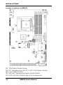
Connectors on MB966 ...................................................... 13
Connector Locations on MB966 ........................................ 14
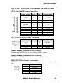
USB_LAN1: 10/100/1000 RJ-45 (MB966) and USB1/2
Ports ................................................................................... 15
ATX1: 24-pin ATX Power Connector ............................... 15
ATX_12V1: ATX 12V Power Connector ......................... 15
DIMM1, DIMM2: Channel A DDR3 Socket .................... 15
DIMM3, DIMM4: Channel B DDR3 Socket..................... 15
FAN1/2: CPU Fan Power Connectors ............................... 15
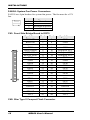
FAN3/4: System Fan Power Connectors ........................... 16
CN1: Front Side Bridge Board to ID370 ........................... 16
CN2: Slim Type II Compact Flash Connector ................... 16
CN3: COM1 Serial Port .................................................... 17
J8: COM2 Serial Port ........................................................ 17
CN4: USB Connector ........................................................ 17
J3: USB Header ................................................................. 17
CN5: SGPIO Connector .................................................... 17
CN6, CN9, CN11, CN12, CN13, CN14, CN15, CN16: LAN
RJ-45 ................................................................................. 18
CN7, CN8, CN10: SATA HDD Connector ....................... 18
J1: LPC Debug Port (Factory use only) ............................. 18
J4: PS2 Keyboard/Mouse Connector ................................. 18
J5: SPI Debug Port (Factory use only) .............................. 18
MB966 User’s Manual
iii