1
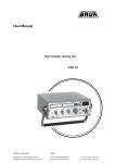
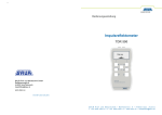
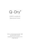
822-164-1 User manual Handheld Time Domain Reflectometer TDR 500 BAUR Prüf- und Messtechnik GmbH Raiffeisenstraße 8 A-6832 Sulz / Austria [email protected] www.baur.eu 822-164-1-phd-12.01.2015 BAUR Prüf- und Messtechnik ▪ Raiffeisenstr. 8 ▪ A-6832 Sulz, Austria T +43 5522 4941-0 ▪ F +43 5522 4941-3 ▪ www.baur.eu ▪ [email protected] t User manual TDR 500 / Declaration of conformity 11 D ECLARATION OF CONFORMITY We BAUR Prüf- und Messtechnik GmbH Raiffeisenstraße 8 A-6832 Sulz / Austria [email protected] www.baur.eu declare, under our sole responsibility, that the BAUR product BAUR Time Domain Reflectometer TDR 500 to which this declaration refers, conforms to the following standards or standard documents: Low voltage guideline 2014/35/EU EN 61010-1:2010 EN 60950-1:2006 + A11:2009 + A1:2010 + A12:2011 + AC:2011 + A2:2013 EMC Guideline 2014/30/EU EN 55022:2010 EN 61000-4-2:2009 EN 61000-4-3:2006 + A1:2008 + A2:2010 EN 61000-4-4:2012 EN 61000-4-5:2006 Signed: Torsten Berth, Technical Director Dr. Eberhard Paulus, Director QM/QS Sulz, 30.01.2015 31 / 32 User manual TDR 500 / Delivery scope and options General Battery 4 x 1.5 V alkaline batteries IEC LR6 Automatic switch off 1, 2, 3 min or deactivated Display LCD display (128 x 64 pixel), with background lighting Ambient temperature 10 to +50 °C Storage temperature -20 to +70 °C Dimensions (W x H x D) Approx. 165 x 90 x 37 mm 10 Weight Approx. 350 g (12 oz.) Degree of protection IP 54 Safety and EMC CE-compliant in accordance with Low Voltage Directive (2014/35/EU) and EMC Directive (2014/30/EU) D ELIVERY SCOPE AND OPTIONS Standard delivery 30 / 32 BAUR handheld time domain reflectometer TDR 500 Connection cable with 2 crocodile clips Carrying bag incl. carrying strap User manual © 2014 All rights reserved. Reproduction, circulation in any form whatsoever, publishing on online services or Internet, as well as duplication on data carriers, even in extracts or with changed format is allowed only with prior written permission of BAUR Prüf- und Messtechnik GmbH, A-6832 Sulz / Austria. We reserve the right in the interests of our customers to make amendments as a result of further technical development. Illustrations, descriptions and scope of supply are therefore not binding. The names of products and companies are the trademarks or brand names of the relevant companies. User manual TDR 500 / Technical data 9 T ECHNICAL DATA Cable fault location Output pulse 5 Vpeak-to-peak (in open circuit) Output pulse width 3 ns – 3 ms Output impedance 25, 50, 75 or 100 Ω; adjustable Overvoltage protection AC 250 V Sampling rate 2 measurements/s or single measurement (not in 3 km /6 km range) Audio frequency generator: 810 – 1100 Hz Measurement range Metre (Feet) Kilometre (Feet) 7 (23) 15 (49) 30 (98) 60 (197) 120 (394) 250 (829) 500 (1,640) 1 (3,280) 2 (6,560) 3 (9,850) 6 (19,000) Measurement range selection: Manual Propagation speed Adjustable: between 1 – 99% as velocity factor (ratio of the transmitted pulse speed to the speed of light) in m/µs or ft/µs (displayed as v/2)* *The conversion is based on the value Vp % UC (accuracy ±1 digit). Resolution Approx. 1% of measurement range Accuracy 1% of selected measurement range (at homogeneous propagation speed) 29 / 32 User manual TDR 500 / Transportation and storage 8 User manual TDR 500 / Table of contents T RANSPORTATION AND STORAGE Table of contents 8.1 Transportation 1 If you are sending the TDR 500 to BAUR Prüf- und Messtechnik GmbH, a BAUR representative or to the technical service for repairs, observe the following: During transport, comply with the ambient conditions specified in the technical data of the product. Information on the technical data is given in the corresponding chapter of this user manual. Protect the device against strong vibrations. Protect the device against humidity. 8.2 Storage During storage, comply with the ambient conditions specified in the technical data of the product. Information on the technical data is given in the corresponding chapter of this user manual. Protect the device and its components from humidity. If the instrument is not to be used for a period of more than 60 days, it is recommended that the batteries are removed and stored separately. General .............................................................................................. 7 1.1 Using this manual ...................................................................... 7 1.2 Application of instructions .......................................................... 7 1.3 Structure of safety instructions .................................................. 7 1.4 Symbols used ............................................................................ 9 1.5 Information on the screenshots and graphics used ................... 9 1.6 Warranty .................................................................................... 9 1.7 After Sales Service .................................................................... 9 2 For your safety ................................................................................. 10 2.1 Instructions for the user ........................................................... 10 2.2 Intended use ............................................................................ 11 2.3 Avoiding dangers, taking safety measures .............................. 11 2.3.1 Dangers when working with high voltage ..................... 12 3 Product information .......................................................................... 14 3.1 Full illustration .......................................................................... 15 3.2 Accuracy .................................................................................. 16 4 First operation .................................................................................. 16 4.1 Preparing the TDR 500 for use ................................................ 17 4.2 Menu and screen displays ....................................................... 17 4.3 Set auto shutdown ................................................................... 18 4.4 Set unit of measure.................................................................. 18 4.5 Set cable impedance (Z).......................................................... 19 4.6 Set velocity of propagation (Vp) ............................................... 19 4.7 Set contrast ............................................................................. 20 4.8 Backlight .................................................................................. 20 28 / 32 5 / 32 User manual TDR 500 / Table of contents User manual TDR 500 / Troubleshooting 3. 4.9 How to determine Vp settings .................................................. 20 5 Using the TDR 500........................................................................... 21 5.1 Testing a cable ........................................................................ 22 Use a soft cloth lightly dampened with soapy water, wipe over the instrument, rinse the cloth in clean water squeezing out any excess water, wipe over the instrument removing any soap residue, dry instrument with a dry cloth. 5.2 Selecting range scales............................................................. 23 5.3 Single shot and continuous scanning modes ........................... 23 5.4 Gain adjustment....................................................................... 23 7 T ROUBLESHOOTING 5.5 Tone generator ........................................................................ 24 5.6 Set contrast ............................................................................. 24 5.7 Typical fault displays................................................................ 25 5.8 Typical cable Vp and impedance values.................................. 25 6 Maintenance..................................................................................... 26 6.1 Battery replacement................................................................. 26 6.2 Cleaning .................................................................................. 26 7 Troubleshooting ............................................................................... 27 8 Transportation and storage .............................................................. 28 8.1 Transportation ......................................................................... 28 8.2 Storage .................................................................................... 28 9 Technical data .................................................................................. 29 10 Delivery scope and options .............................................................. 30 11 Declaration of conformity ................................................................. 31 6 / 32 NOTICE Damage to devices due to improper handling. The user is liable for damages caused due to improper maintenance or care. Never take apart the device. This can lead to damages to the device. Inside the device there are no components that could be serviced or repaired by the user. Repair work must be carried out only by qualified and authorised personnel from BAUR. The instrument contains static sensitive devices and is not user serviceable. If an instrument fails, or its protection has been impaired, it should not be used but sent back for repair by suitably trained and qualified personnel. When a fault occurs, proceed as follows: 1. Check the charge status of the device battery. 2. Restart the device. 3. If the error occurs again after the device has been restarted, contact your nearest BAUR representative (http://www.baur.eu/baur-worldwide/). It may be possible for the BAUR Prüf- und Messtechnik After Sales Service Team to determine the cause of the fault remotely. To do so, please specify the following data: Device serial number Firmware version Procedure that caused the error. 27 / 32 User manual TDR 500 / Maintenance 6 M AINTENANCE NOTICE User manual TDR 500 / General 1 1.1 The user is liable for damages caused due to repairs. 6.1 Never take apart the device. This can lead to damages to the device. Inside the device there are no components that could be serviced or repaired by the user. Maintenance work must be carried out only by qualified and authorised personnel from BAUR. Battery replacement 1. 2. 3. 4. 5. 6.2 Disconnect the instrument from any cable or network link. Turn the instrument off. Loosen the two black screws and remove the battery compartment cover. Replace the batteries with 4 x 1.5 V alkaline batteries, observing the polarities. Refit the battery compartment cover and refit the two screws. Cleaning Using this manual Read the entire user manual before operating the product for the first time. Consider this user manual as part of the product and keep it in an easily accessible location. This user manual contains all necessary information that is needed for the fault location with TDR 500. If this user manual is lost, please contact BAUR Prüf- und Messtechnik GmbH or your nearest BAUR representative (http://www.baur.eu/baurworldwide/). Damage to devices due to improper handling. G ENERAL 1.2 Application of instructions This user manual applies for devices with the firmware version from 2.02. 1.3 Structure of safety instructions The safety instructions in this user manual are presented as follows: Danger symbol SIGNAL WORD Type of danger and its source Possible consequences of violation. NOTICE Measure to prevent the danger. Damage to devices due to improper handling. 26 / 32 Do not use alcohol, solvents or hydrocarbons. Ensure material compatibility. Do not splash water directly on the instrument 1. 2. Disconnect the instrument from any source of electricity. Turn the instrument off. 7 / 32 User manual TDR 500 / General If a dangerous situation could arise at a specific step, the safety instruction is displayed immediately before this dangerous step and is shown as follows: User manual TDR 500 / Using the TDR 500 5.7 Typical fault displays The following diagrams show typical fault traces to assist you in the identification of faults using the TDR 500: SIGNAL WORD Type of danger and its source Possible consequences of violation. Measure to prevent the danger. Danger levels Signal words in the safety instructions specify the danger levels. DANGER Will lead to severe injuries or death. WARNING May lead to severe injuries or death. CAUTION May lead to light to moderate injuries. NOTICE May lead to material damage. Danger symbols Nr. Fault 1 Open conductor 6 Wet splice/water 2 Shorted conductor 7 Frayed cable 3 Splice 8 Water ingress 4 Bridge tap 9 Tap 5 Split/resplit 10 Splitter General danger 5.8 Typical cable Vp and impedance values Risk of electric shock 8 / 32 Type Vp Z Type Vp Z Cat5 STP 72 100 T/Pair Jelly PE 64 100 Cat5 UTP 70 100 T/Pair PE 67 100 Coax Air 98 50/75 T/Pair PTFE 71 100 Coax Air Space 94 50/75 T/Pair PVC 58 100 Coax Foam PE 82 50/75 T/Pair Paper 72nF 88 100 Coax Solid PE 67 50/75 T/Pair Paper 83nF 72 100 25 / 32 User manual TDR 500 / Using the TDR 500 User manual TDR 500 / General 1.4 5.5 Tone generator Symbol The TDR 500 may also be used as a tone generator to trace and identify cables and wires. The user will need a conventional inductive tone probe within the range 810 Hz to 1,110 Hz. Selecting tone generator (Level 2) 1. Press 2. To open the 3. 4. To exit press . When tone has been selected, connect test lead to cable pair to be traced. Trace the cable using tone probe which will emit a tone. The volume will increase the nearer the probe is to the cable. 5. or to select . menu press SELECT. 1.5 1.6 2. To open the 3. Press 4. To exit press or or 1. 2. [...] Perform the actions in this sequence. a. b. [...] If an operation consists of several operating steps, specify these with "a, b, c". Perform the operating steps in this sequence. 1 2 [...] Numbering in the legend List Information on the screenshots and graphics used Warranty For warranty claims, please contact BAUR Prüf- und Messtechnik GmbH or your local BAUR representative (http://www.baur.eu/baur-worldwide/). Warranty is cancelled in case of misuse. 1.7 Press You are prompted for an action. The screenshots and graphics used are intended to illustrate the procedure and may therefore differ slightly from the actual state. Set contrast 1. Meaning Indicates extensive information on the topic in the corresponding user manuals. Note: The auto shutdown function is disabled in tone generator mode so that the tone can be injected into a cable for extended periods while tracing takes place. 5.6 Symbols used to select . menu press SELECT. to increase or decrease contrast. . After Sales Service For questions contact BAUR Prüf- und Messtechnik GmbH or your BAUR representative (http://www.baur.eu/baur-worldwide/). BAUR Prüf- und Messtechnik GmbH Raiffeisenstraße 8 6832 Sulz / Austria [email protected] www.baur.eu 24 / 32 9 / 32 User manual TDR 500 / For your safety 2 User manual TDR 500 / Using the TDR 500 F OR YOUR SAFETY All BAUR devices and systems are reliable and are manufactured as per state-of-the-art technology. The individual parts and the finished devices are subject to continuous testing by our qualified personnel as part of our quality assurance system. Each device is fully tested before delivery. On the fault display shown above a low impedance fault occurs at 64 meters shown by a negative spike, and high impedance at 129 meters. To increase the gain of the return pulse see chapter 5.4. The open end of the cable is shown as a large positive spike, this is used to determine the end of the cable route and the overall length of the cable being 180 meters. 5.2 The TDR 500 has 11 range scales covering the range of 7 to 6,000 meters. To select a range scale, or scan the cable route, press and hold down the RANGE button and press to decrease range, press to increase range. However, the operational safety and reliability in practice can be achieved only when all necessary measures have been taken. The responsible body1 2 and operator of the device or system are responsible for planning these measures and monitoring their implementation. Before operating the device or system you should read and understand this user manual and the user manuals of all integrated devices. 2.1 5.3 The product may be operated only by authorised and trained electrical engineers. An electrical engineer is a person who owing to his professional education (electrical engineering), knowledge, experience and acquaintance with the applicable standards and regulations can assess the tasks assigned to him and detect possible dangers. When the TDR 500 is first switched on, it is set to “Single shot” mode. In this mode the TDR 500 only fires a pulse into the cable under test when either button is pressed. the and buttons or Continuous scanning mode: Fires pulses into the cable under test. In this mode the TDR 500 is able to more easily identify intermittent cable faults. To enter “Continuous scanning” mode press down and hold the button. In addition, the user must have: Knowledge of the technical equipment and operation of TDR 500 Knowledge of the testing and measurement procedures Knowledge of plant engineering (cable types, switchgear, etc.). Single shot and continuous scanning modes Single shot mode: Saves on battery life and also enables the TDR 500 to be disconnected from the cable while still leaving the fault display on the screen Instructions for the user Selecting range scales The icon will appear at the bottom right of the display, when continuous scanning mode is activated. 5.4 Gain adjustment 1. To increase the gain of the return pulse, align the cursor at the beginning of the event. 2. Press and hold decrease gain. button and press or keys to increase or 1 Responsible body is the person or group that is responsible for the safe operation of the device and its maintenance (EN 61010-1, 3.5.12). Operator is the person who uses the device for its intended purpose (according to the definition of user in compliance with EN 61010-1, 3.5.11). 10 / 32 2 23 / 32 User manual TDR 500 / Using the TDR 500 User manual TDR 500 / For your safety 2.2 Intended use The BAUR handheld time domain reflectometer TDR 500 is used for fault location in all metal cables such as power cables, coaxial cables, data cables and communication cables. The TDR 500 is designed for use on deenergised circuits only. This device meets the immunity requirements of telecom networks according to EN 61326-1. If the device is used without observing this condition, safe operation cannot be guaranteed. The operator or user is liable for any damage to persons and property resulting from incorrect operation. Proper use also includes 5.1 Compliance with all instructions in this user manual, Compliance with the technical data and connection requirements given on the rating plate and in the user manual, Compliance with the inspection and maintenance tasks. Testing a cable Having followed the set up procedures in the preceding chapters, a typical display showing impedance anomalies is shown below. Further examples are shown in chapter 5.7 (page 25). 1. 2. 22 / 32 To determine the distance move the vertical cursor line left or right along the line of the trace to the event by pressing or . Position the cursor at the beginning of the event and read off the distance at the bottom left corner. 2.3 Avoiding dangers, taking safety measures When installing the test system and operating the TDR 500 observe the following rules and guidelines: Accident prevention and environment protection rules applicable for your country Safety instructions and regulations of the country where TDR 500 is being used (according to the latest version) EU/EFTA countries: EN 50110 “Operation of electrical installations” Other countries: The standards for operating electric systems applicable in your country If necessary, other national and international standards and guidelines in the latest applicable version Local safety and accident prevention regulations Employers’ liability insurance association regulations (if any) 11 / 32 User manual TDR 500 / For your safety Technically secure state of the device Safety, function and availability depend on the proper condition of the device. Upgrades, modifications or alterations to the product are prohibited. Operate the device only in a technically perfect condition. In the case of damage and/or malfunction, immediately stop the device, identify accordingly and have the faults rectified by appropriately qualified and authorised personnel. Comply with the inspection and maintenance conditions. Use only accessories and original spare parts recommended by BAUR. The use of spare parts, accessories and optional extras that are not tested and approved by BAUR could adversely affect the safety, function and characteristics of the product. Never take apart the device. The device does not contain any components that could be serviced or repaired by the user. 2.3.1 User manual TDR 500 / Using the TDR 500 5 U SING THE TDR 500 DANGER Dangerous electric voltage Danger to life or risk of injury due to electric shock. 1. Before test connections are made, switch off, de-energise and isolate the circuit under test. Upon completion of the set up procedures in chapter 4, press button and the following test screen will be displayed Dangers when working with high voltage Although this device does not produce dangerous voltages, the electric circuits to which it is connected could present danger of electric shock or formation of electric arcs. The personnel need to pay special attention and must be very careful while working with high electric voltage. Commissioning and operation of TDR 500 are permitted only in compliance with the EN 50110 (EU/EFTA countries) or with standards applicable in your country. 1 2 3 4 5 6 7 8 Observe 5 safety rules Comply with the following safety rules before beginning tasks in and on electrical plant: Disconnect the test object. Secure against re-energisation. Ascertain the voltage status of the disconnected object. Short-circuit the test object to earth. Protect or isolate the test object from adjoining live HV plant. 2. 3. 4. 5. 12 / 32 Vp setting Impedance setting (Z) Range scale 7 m Scan mode icon (indicating scan mode selected) Selected gain value Distance of cursor Output pulse Cursor Attach the test lead set to the TDR 500 via the connectors located at the top of the unit. Ensure that no power supply or equipment is attached to the cable to be tested. Ensure that the far end of the cable under test is open or shorted (not fitted with a resistive termination) Attach the TDR 500 to one end of the cable to be tested 21 / 32 User manual TDR 500 / First operation 4.7 User manual TDR 500 / For your safety Set contrast DANGER High electric voltage 4.8 1. 2. Select using the keys. Press SELECT key to open. 3. Press 4. To open the or or 5. Press 6. To exit press to select . Danger to life or risk of injury due to electric shock Before commencing work, the operator must assess the risks for the specific working conditions. Protective measures are based on the risk assessment and must be followed at the workplace. The TDR 500 is designed for use on de-energised circuits only. The circuit under test must be switched off, deenergised, securely isolated and proved safe before test connections are made. menu press SELECT. to increase or decrease contrast. . Backlight The LCD display is fitted with an LED backlight to enable easy viewing under a variety of different lighting conditions. The backlight is switched on and off with the key. 4.9 Always keep your hands behind guards on the probes and crocodile clips. Connect the device as described in this user manual. Before lifting the safety measures, all live parts must compulsorily be discharged, earthed and short-circuited. How to determine Vp settings If the TDR 500 is to be used with a cable type for which the Vp is unknown, this must first be determined. 1. Take a sample of the cable at least 100 m or 300 ft long. 2. Measure the actual length of cable using a rule or tape measure, or some other reliable method. 3. Connect the TDR 500 and adjust the Vp setting such that the tester gives a correct reading of the sample length. 20 / 32 Connection to lines under voltage will damage the instrument and could be hazardous to the operator 13 / 32 User manual TDR 500 / Product information 3 User manual TDR 500 / First operation P RODUCT INFORMATION The TDR 500, 6 km (19,000 ft.) range handheld time domain reflectometer weighing only 350 grams (12 oz.) fits neatly into the hand. With its 128x64 pixel backlight display, provides accurate and easy to read fault locations on metallic cables. With a 3 nanosecond pulse rise time, “near end” cable faults can be clearly identified without the need to suppress the transmitted pulse. Housed in a rugged IP 54 rated ABS enclosure, the TDR 500 is suitable for outside use. Using pulse widths and gain settings which are pre-determined for the length range selected and with only 7 operating buttons, all major operating and setting parameters can be easily accessed. In addition to the pre-determined gain settings there is a user variable gain control to further enhance the displayed trace. A 6 km cable route can be scanned in seconds, allowing the operators a view of the cable route, yet arriving quickly to the fault. By using the TDR 500 scan lock facility, cable can be continually scanned or the trace held for closer analysis. To enable the TDR 500 to test all metallic cables, four user selectable output impedances are provided 25, 50, 75 and 100 ohms. Faulty cables may be traced using the TDR 500 warble tone feature, an oscillating tone is injected into the suspect power or transmission line and by using a commercially available tone tracing probe the suspect line can be identified. 3. Press to move 4. Press or 5. To exit press to unit of measure (feet or meters). to scroll between feet and meters. . Selected values will be automatically stored. Note: When unit of measure has been selected, this will automatically change the V/2 figure, which will also be displayed in the selected unit of measure (ft./m). 4.5 Set cable impedance (Z) 1. 2. 4.6 Select using the keys. Press SELECT key to open. 3. Press to move 4. Press or to Z. 5. To exit press . Selected values will be automatically stored. to scroll between values. Set velocity of propagation (Vp) Velocity of propagation (Vp) may be set as % UC or speed in micro seconds (µs). The unit of measure, the speed is displayed in (feet or meters), will be determined by the setting selected in chapter 4.4. The conversion is based on the value Vp % UC (accuracy ±1 digit). 1. 2. 14 / 32 Select using the keys. Press SELECT key to open. 3. Press to move 4. Press to scroll between V/2 m/us or Vp % UC. 5. Press to move 6. Press or 7. To exit press . Selected values will be automatically stored. to displayed unit. to displayed value. to increase or decrease displayed value. 19 / 32 User manual TDR 500 / First operation User manual TDR 500 / Product information Level 2: Menu 1. To access level 2 Menu press 2. To change the following settings from menu, select keys. Press SELECT key to open. 3. 4.3 3.1 and release. Full illustration using the Set auto shutdown To preserve battery life, the TDR 500 is fitted with an auto shutdown feature. Shutdown time is selectable between disabled 1 minute, 2 minutes and 3 minutes. 4.4 1. 2. Select using the keys. Press SELECT key to open. 3. To change settings press 4. Press 5. To exit press . Selected values will be automatically stored. Note: The shutdown feature isn’t active if the settings menu is open. to shut down. to select setting. Set unit of measure 1. 2. 18 / 32 or to move using the keys. Select Press SELECT key to open. Nr. Element 1 Connections for measuring cables 2 LCD display 3 Menu/Cursor right button / increase range 4 Select/Gain button 5 Back/Measuring range button 6 Power on/off button 7 Backlight on/off button 8 Start test button 9 TDR/Cursor left button / decrease range 15 / 32 User manual TDR 500 / First operation 3.2 Accuracy User manual TDR 500 / First operation 4.1 Press button to power the tester, the following screen will be displayed: The TDR 500 is able to measure distances to faults and cable lengths to an accuracy of +/- 1%. This measurement accuracy is based on the correct velocity of propagation (Vp) value being used for the cable under test, and homogeneity of the Vp along the cable length. If the Vp is set incorrectly by the operator, or the Vp varies along the length of the cable, then additional errors will be incurred and the measurement accuracy will be affected. Note: The Vp is less well defined with unshielded multicore cable, including power cable, and is lower when a cable is tightly wound on a drum than when installed. 4 F IRST OPERATION 16 / 32 The safety instructions in the chapter For your safety (on page 10) Local safety and accident prevention regulations Safety instructions and regulations according to the state-of-the-art National and international standards and guidelines in the latest applicable version: EN 50110 for operation of electric systems (EU/EFTA countries); or applicable standards in your country. No. Element 1 Model 2 Battery condition indicator (all black battery, fully charged, as charge decreases symbol changes to white). 3 Software version programmed into device Prior to use the following parameters will need to be set Observe the following information: Preparing the TDR 500 for use 4.2 Set auto shutdown: chapter 4.3 (page 18) Set contrast: chapter 5.6 (page 24) Set unit of measure: chapter 4.4 (page 18) Set velocity of propagation: chapter 4.6 (page 19) Menu and screen displays Level 1: Start-up screen 17 / 32